
Chapter 6
Character Poly Modeling
Organic modeling is typically used when you create natural objects, such as a tree trunk, a hilly landscape, or a character. These models are generally of a higher polygon count than most because organic models require smooth surfaces and need to be seamless. With a more mechanical model, such as the dresser you modeled in Chapter 4, “Modeling in 3ds Max: Part I,” there is little to no need for highly detailed, high-polygon-count surfaces. A human head model for a character, however, needs finely detailed surfaces because an organic model’s parts need to flow together seamlessly. With the human head model, there should be no clear distinction between where the geometry of the lower lip stops and the jaw starts, or where the top of the nose ends and the forehead begins. A basic knowledge of anatomy and an understanding of balance and proportion are important when you’re designing a character that needs to be appealing and believable.
Realistic computer-generated (CG) characters are already very common in television and films; they appear as stunt doubles, as vast crowds of people, and even as primary characters to the scene or even the entire show. There are several situations where using a CG character works better for a show than using a real person. For example, CG stunt doubles are safer and sometimes cheaper than using an actual stunt person. Another opportunity for organic character modeling arises when a storyline calls for an unusual or nonhuman character. Weird creatures can be created with better clarity using CG than using puppetry or special makeup effects.
This chapter introduces you to character modeling, focusing on using the Editable Poly toolset to create a relatively low polygon count soldier model suitable for character animation and for use in a game engine (though that is not covered in this book). The model of a special operations soldier character frequently seen in a game will finish as a single object created from very basic forms. However, the concepts and practices talked about in this chapter will give you a solid foundation for any kind of character modeling.
Topics in this chapter include the following:
- Setting up the scene
- Creating the soldier
As mentioned throughout the previous chapters, acquiring and utilizing good reference material is essential for creating a successful character. At the minimum, sketches of the character’s front and side features are necessary. You can import and use these views as background images as you create the character in 3ds Max. Additional perspective sketches of your intended character from several points of view and sketches of specific features, such as headgear, weapons, or other devices, can be very helpful during the modeling process for quick reference to your goal.
High- and Low-Poly Modeling
High polygon count models are used when a model’s level of detail needs to be impeccable, such as when the model is used in close-ups. In such a case, detail is favored over efficiency.
Low polygon count modeling, also called low poly modeling, refers to a style of modeling that sacrifices some detail in favor of efficient geometry that places a very low load on the system on which it is being created or rendered. Because they require less memory, can be easier to animate, and can render quickly, low-poly models are especially useful in games, as well as for filling in a scene’s background without overly taxing the scene.
Creating Planes and Adding Materials
Like the toy rocket exercise in Chapter 5, “Modeling in 3ds Max: Part II,” this exercise begins by creating crossed boxes and applying reference images to them.
1. In a new scene, go to the Front viewport and create a plane.
2. In the Parameters rollout of the Command panel, set the Length to 635 and the Width to 622. The units are in inches, which is the default in 3ds Max. The size of the image planes in units is the same size as the reference images in pixels. Thus, when we apply the image to the plane it will be proportional, maintaining its width and length with no stretching or squeezing of the images.
3. Rename this box Image_Plane_Front.
4. With the plane still selected, click the Move tool (![]() ) in the Main toolbar. In the Transform Type-Ins at the bottom of the user interface, move the plane to these coordinates: (0.0, 80.169, -5.228), as shown in Figure 6-1
) in the Main toolbar. In the Transform Type-Ins at the bottom of the user interface, move the plane to these coordinates: (0.0, 80.169, -5.228), as shown in Figure 6-1
Figure 6-1: Use the Transform Type-ins to move the image plane to the given coordinates.
5. Click the Z key on the keyboard; it is the shortcut for Zoom Extents All. Then, in the Main toolbar, turn on the Angle Snap toggle (![]() ). This will snap your rotation to every 5 degrees. This will make getting an exact rotation easier. Select the Rotate tool and hold down Shift on the keyboard, then in the Front viewport rotate the image plane along the Y-axis -90 degrees. Using Shift activates the Clone tool, as shown in Figure 6-2.
). This will snap your rotation to every 5 degrees. This will make getting an exact rotation easier. Select the Rotate tool and hold down Shift on the keyboard, then in the Front viewport rotate the image plane along the Y-axis -90 degrees. Using Shift activates the Clone tool, as shown in Figure 6-2.
Figure 6-2: Clone Options dialog box

6. In the Clone Options dialog box, under Object, select Copy, then name it Image_Plane_Side and hit OK.
7. Switch to the Move tool and move the plane to these coordinates: (-159.85, 80.169, -5.228), as shown in Figure 6-3.
Figure 6-3: Image plane coordinates
Figure 6-4: The current Layer toggle in the Layer Manager. Check the box next to the 0 (default) layer.
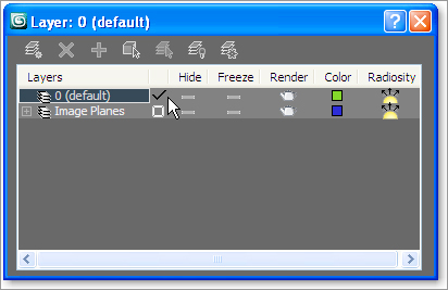
Figure 6-4: The current Layer toggle in the Layer Manager. Check the box next to the 0 (default) layer.
8. Now that both image planes have been created and positioned, open the Layer Manager. Select both image planes, and in the Layer Manager click the Create New Layer. Because the image planes were selected when you created the new layer, the image planes were automatically added to the new layer. Rename the layer Image Planes, and check the Current Layer column next to the 0 (default) layer, as shown in Figure 6-4.
9. In the Layer Manager, click on the Layer icon for the Image Planes layer to open the Layer Properties dialog box, as shown in Figure 6-5.
Figure 6-5: Click the Layer icon to open the Layer Properties dialog box.

10. Uncheck the Show Frozen in Gray box. This will allow you to freeze the image planes and still see the images on the planes.
11. Click OK then click the Freeze column next to the Image Planes layer.
Adding the Materials
The reference materials are then texture mapped onto the planes to provide reference inside the scene itself while you model the character. Therefore, it’s critical to ensure that the features of the character that appear in both reference images (the front and the side) are at the same height. For instance, the top of the head and the shoulders should be at the same height in both the front and side views to make the modeling process easier, eliminating as much guesswork as possible.
1. In the Front viewport, change the viewport shading to Smooth + Highlights (F3). Change a viewport so it is a Right view, press the V key on the keyboard, and select Right View from the list. Change the shading in the Right viewport to Smooth + Highlights.
2. Open an Explorer window and navigate to the Soldier/sceneassets/images folder on your hard drive from the Soldier project you downloaded from the web page at www.sybex.com/go/3dsMax2011. Drag ImagePlane_Front.jpg from the Explorer window to the image plane in the Front viewport.
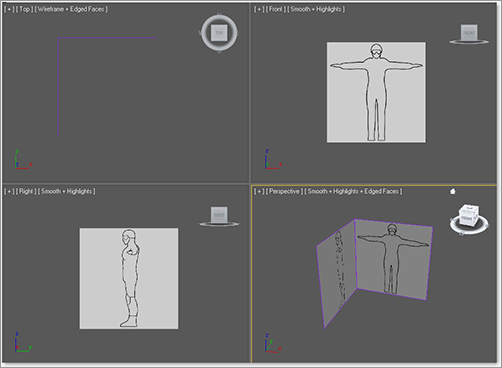
3. Drag ImagePlane_Side.jpg onto the image plane in the Right viewport. The image planes should have the two images mapped on them, as shown in Figure 6-6.
Seeing Quality Bitmaps in the Viewports
The Show Map in the Viewport toggle (![]() ) in the Material Editor determines whether the maps in a material are displayed in all viewports set to the Smooth + Highlights display mode. In many cases, the quality of the images displayed is high enough to allow you to line up major features in the reference image to the model’s corresponding feature, but not high enough to have a very effective reference. The quality level of the bitmap display can be set in the Preference Settings dialog box. The following steps explain how to change the bitmap viewport quality when using the DirectX video driver. The steps to follow when using the OpenGL or Software drivers are similar.
) in the Material Editor determines whether the maps in a material are displayed in all viewports set to the Smooth + Highlights display mode. In many cases, the quality of the images displayed is high enough to allow you to line up major features in the reference image to the model’s corresponding feature, but not high enough to have a very effective reference. The quality level of the bitmap display can be set in the Preference Settings dialog box. The following steps explain how to change the bitmap viewport quality when using the DirectX video driver. The steps to follow when using the OpenGL or Software drivers are similar.
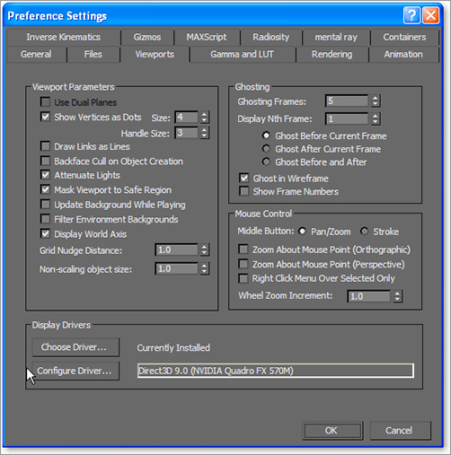
1. From the main menu, select Customize ⇒ Preferences.
2. Click the Viewports tab, and then click the Configure Driver button in the Display Drivers section, as shown here.
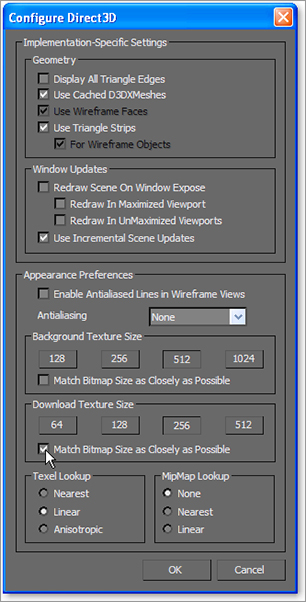
3. In the Configure Direct3D dialog box that appears, select a resolution in the Download Texture Size section or select the Match Bitmap Size as Closely as Possible option. This allows you to increase the displayed resolution of any maps shown in the viewports. This does not affect the actual size of the images used in the scene, only how they are shown in the viewports.
4. If necessary, repeat step 3 to increase the resolution of the background image in the Background Texture Size section.
5. Click OK in both dialog boxes to accept the changes. You must close and then reopen 3ds Max for the changes to take effect, however.
Beware that increasing the displayed resolution can decrease viewport performance and increase the system resources required to manage the scene.
Figure 6-6: Mapped image planes in viewports
The soldier character we are modeling here is pretty common: one head, one neck, two arms, a torso, and two legs—a typical, bipedal human 3D character.
When you create an organic character, you might be tempted to model one piece of the final product, such as the head or hands, to completion before you begin modeling another piece of the character. This is rarely a good idea, because the scale and balance of the components must be built together from the beginning. A better practice is to block out the basic form of the character and focus on the size and crucial shapes of the major elements, and then add detail for the finer features. The following exercises describe the steps required to block out the soldier’s major features. When you have gained enough confidence, we encourage you to step back into this soldier exercise and redesign the soldier with more intricate features, or even add an additional set of arms to the torso. Go wild!
Forming the Torso
The basic structure for the torso will begin with a simple box primitive. After converting the box into an Editable Poly, you will use the Mirror tool on the object so that any manipulations performed on one side are also performed on the other. You will begin forming the basic shape of the torso by moving the Editable Poly’s vertices and extruding its polygons in the following steps.
Continue with the previous exercise’s scene file, or open the Soldier_V01.max scene file in the Scenes folder of the Soldier project downloaded from this book’s companion web page at www.sybex.com/go/intro3dsmax2011.
1. Select each viewport and press F3 and F4 so that Smooth + Highlights with Edged Faces is the display mode.
2. Start by creating a box primitive in the Perspective viewport with these parameters: Length: 25, Width: 16, Height: 53, Input Height Segs: 8. Leave the Width and Length Segs at 1 (see Figure 6-7). This is a starting point for the detail needed to create the form of the body. Position the box as shown in Figure 6-8. Press Alt + X to make the box see-through. Change the box’s name to Soldier.
Figure 6-7: Box parameters

Figure 6-8: Box position from the front and side views

3. In the Graphite Modeling Tools ribbon, click Polygon Modeling ⇒ Convert to Poly (as shown in Figure 6-9).
Figure 6-9: Convert the soldier box to an editable Polygon.

4. Enter the Vertex sub-object level. In the Right viewport, position the vertices on the right side of the box to match the side outline of the character on the image plane, as shown in Figure 6-10.
5. In the Graphite Modeling Tools ribbon, click Edit ⇒ SwiftLoop. Use the SwiftLoop tool to create two new edge loops that run vertically from the front of the model to the back, as shown in Figure 6-11. The dashed lines show the loop running in the back and bottom of the model.
Figure 6-10: Move vertices to match the soldier image in the Right viewport.
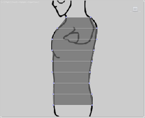
Figure 6-11: Create two new edge loops using SwiftLoop.
6. Repeat step 5 but create a single new edge on the side of the model running from the left side to the right side, as shown in Figure 6-12. The dashed lines show the loop running across the bottom of the model.
Figure 6-12: Create a single new edge on the side of the model using SwiftLoop.
7. Now round the side of the torso. Switch to Edge mode and select one of the edges running vertically on the side of the torso box. In the Graphite Tools Modeling ribbon go to the Modify Selection tab and press Loop to select the loop of edges running along the side of the torso (Figure 6-13). Move the loop of edges toward the back of the model to begin rounding that edge. Then select the loop of edges to the left of the previous loop with the Loop tool and move them back to form a more rounded front to the torso, as shown in Figure 6-13.
Figure 6-13: Select and move edges toward the back of the model.

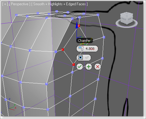
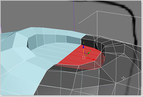
8. Switch to Vertex mode and select the vertex on the left side below the top edge, as shown in Figure 6-14. In the Graphite Tools Modeling ribbon’s Vertices tab, select Chamfer Settings by clicking the tool’s name under the icon. This opens the tool caddy shown in Figure 6-15. Use a Vertex Chamfer Amount value of 4.808 as shown, and click the green checkmark button (OK) in the caddy to commit the action. This is where the arm will be positioned.
Figure 6-14: Select the vertex right above the mouse cursor shown here.

Figure 6-15: Use Chamfer to create a new polygon where the arm will be positioned.
9. Switch to Polygon mode, select the new diamond-shaped polygon in the middle, and press Delete to delete the polygon. A hole appears where the arm will be positioned.
10. Switch to Edge mode and select the four diagonal edges of the diamond-shaped hole and the four edges shown in Figure 6-16.
11. Select the Graphite Modeling Tools ribbon ⇒ Modify Selection ⇒ Ring to select the ring of edges running across the top of the chest. Select Modeling ribbon ⇒ Loops ⇒ Flow Connect to create more horizontal divisions for the upper chest. The newly created edges are illustrated in Figure 6-17. The diamond-shaped hole in the shoulder is now more rounded (the hole is now an octagon) as well, since more edges were created at the hole, too. The dashed lines show the loops running behind the model.
12. Select the two horizontal edges under the armhole (left image in Figure 6-18), and select Modeling ribbon ⇒ Modify Selection ⇒ Ring to select the horizontal edges running down the side of the torso. Select Modeling ribbon ⇒ Loops ⇒ Flow Connect to create two new loops of edges, shown on the right in Figure 6-18.
Figure 6-16: Select these eight edges.

Figure 6-17: Use Flow Connect to create two new edges around the model.

Figure 6-18: Select the two horizontal edges under the armhole (left) and use Flow Connect to create more edges (right).
13. The new edge ring, as you can see in Figure 6-18, does not reach all the way up to the octagon armhole. You will need to cut an edge from the top of the new edges you just made, to the bottom of the armhole. Select Modeling ribbon ⇒ Edit ⇒ Cut to enter the Cut tool. Click on the first vertex under the armhole in Figure 6-19, then click on the second vertex above at the armhole to create the first new edge. Right-click to commit the edge. You will still be in the Cut tool, so click on the third vertex shown in Figure 6-19 and create the second new edge up to the fourth vertex shown in Figure 6-19. Right-click to commit the second edge.
Figure 6-19: Use the Cut tool to add two edges to the armhole.

14. The armhole isn’t great right now; it will be easier to start from a circular shape rather than the uneven octagon form we have now. Enter Border sub-object mode, select the armhole’s border, and in the Graphite Modeling Tools ribbon’s Geometry (All) tab, click the Cap Poly tool to create an NGon (a polygon with more than four sides) cap to fill the hole.
15. Go to Polygon mode and select the new NGon. Go to the Graphite Modeling Tools ribbon’s Polygons tab and click the GeoPoly tool to create a symmetrical polygon from the previous shape, as shown in Figure 6-20. GeoPoly untangles a polygon and organizes the vertices to form a perfect geometric shape. This will make it easier for us when we create the arm later.
16. Select the new NGon cap you created in step 14 and press Delete to delete the NGon. Also select and delete the top and bottom polygons on the model as shown in Figure 6-21 (left).
17. Under the Graphite Modeling Tools Ribbon tab, under the sub-object mode buttons, turn on Ignore Backfacing (![]() ). Then select the left-side polygons as shown in Figure 6-21 (right) and delete them as well. Your torso should now have only a front, side, and back.
). Then select the left-side polygons as shown in Figure 6-21 (right) and delete them as well. Your torso should now have only a front, side, and back.
18. Now, select the edge loops on the right of the model and move them closer toward the left, and closer to the center of the model (Figure 6-22). You might want to translate them on the Y-axis as well. Your goal is to round out the character for a more organic feel.
Figure 6-20: Use GeoPoly to create a symmetrical shape for the armhole.
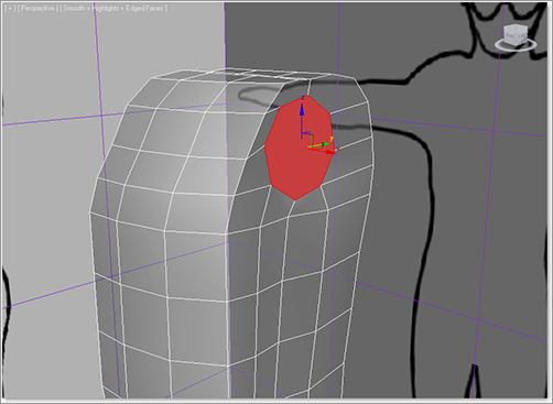
Figure 6-21: Delete the NGon as well as the topmost and bottommost polygons of the model.
Figure 6-22: Select the edge loops and move them to create a more rounded look to the model.
19. Notice how the armhole’s circle looks neat, but the edges on the right and top are a bit awkward. Enter Vertex mode and move the edges to give the armhole a more rounded feel as in Figure 6-23. Try to match the relative size of the hole shown in Figure 6-23, as well.
Figure 6-23: Adjust the Editable Poly’s vertices to match the background image.

Figure 6-24: Move the selected edge toward the front of the torso to round out the back.
20. Go into Edge mode and select the edge running vertically on the right side of the model’s back (as shown in Figure 6-24) and move it toward the armhole. This will make the back rounder.
Now we are starting to see some shape in the torso. Let’s move on to the arms.
Creating the Arms
Continue with the previous exercise’s scene file, or open the Soldier_V02.max scene file in the Scenes file of the Soldier project on the companion web page.
1. In Border mode, select the armhole’s border, then hold down the Shift key, and with the Move tool, drag out from the body on the X-axis, extruding polygons as you drag. This method is a form of Border Extrude. This method gives you more control over the extrude process because you can more easily choose the axis along which to extrude. Release the mouse button and view your model in the Front viewport to line up the border to the wrist of the arm in the image plane, as shown in Figure 6-25.
2. Select Modeling ribbon ⇒ Edit ⇒ SwiftLoop to create three edge loops on the arm, as shown in Figure 6-26.
Figure 6-25: Line up the extruded border with the arm in the image plane.

Figure 6-26: Use SwiftLoop to create three new edges on the arm.
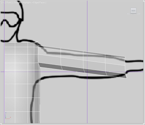
Figure 6-27: Edit vertices to match the shape of the arm.

3. Switch to Vertex mode and move the newly created vertices on the Y-axis to fit the form on the image plane, as in Figure 6-27. It is OK to select a group of vertices and scale on the Y-axis to taper that part of the arm to create the wrist.
4. In Edge mode, select and use Loop selection (Graphite Modeling Tools Ribbon ⇒ Modify Selection ⇒ Loop) on the horizontal edge running around the body under the arm and move the edges down. Repeat the same process with the loop of edges under the previous loop, as shown in Figure 6-28. This ensures the underarm area geometry is lined up properly, as shown later in Figure 6-30.
5. In Edge mode, select and use Loop (Graphite Modeling Tools Ribbon ⇒ Modify Selection ⇒ Loop) on the horizontal edge running directly at the underarm and move the loop down, as shown in Figure 6-29.
6. In the Front viewport, in Edge mode, select the middle edge on the arm, then Select Modeling ribbon ⇒ Modify Selection ⇒ Loop. Then select Modeling ribbon ⇒ Edges ⇒ Chamfer ⇒ Chamfer Settings and enter an Edge Chamfer Amount of 2 and a Connect Edge Segments value of 2.
Figure 6-28: Move these looped edges down.
Figure 6-29: Select and Loop these edges to move them down.
7. Then Chamfer the edges to the right and left, using an Edge Chamfer Amount of 3, with a Connect Edge Segments value of 1 (Figure 6-30). Keep the middle edge a bit tighter together. Since this is the area where the elbow bends, it is a good idea to include more detail there for deformations at the elbow. Your model should have the vertical edges you see in Figure 6-30.
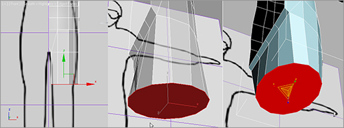
8. In Border mode, select the wrist border and, while holding down the Shift key, use the Scale tool to scale the wrist border down on the Z- and Y-axes into the center, as shown in Figure 6-31 (left). Using Shift while performing a Scale operation clones the selected objects much like an extrusion with the Shift + Move method used before. In this case, it makes a copy of the border, effectively closing the open end of the wrist.
9. Then switch to Vertex mode, select the vertices of the smaller wrist hole, and select Modeling ribbon ![]() ) to open the Weld tool caddy (Figure 6-31 (middle). Use a Weld Threshold of 3.39, as shown. This creates a completed cap at the end of the arm shown in Figure 6-31 (right). We will continue with the hand in a later section.
) to open the Weld tool caddy (Figure 6-31 (middle). Use a Weld Threshold of 3.39, as shown. This creates a completed cap at the end of the arm shown in Figure 6-31 (right). We will continue with the hand in a later section.
Figure 6-30: Chamfer the arm to add more edges for detail.
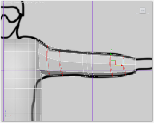
Figure 6-31: Fuse the wrist edge in toward the center.

Creating the Legs
Continue with the previous exercise’s scene file, or open the Soldier_V03.max scene file in the Scenes folder of the Soldier project downloaded from the companion web page.
1. In Edge mode, select the bottommost loop of edges on the model’s torso and Shift + Move (hold down the Shift key while moving with the Move tool, as you did in the previous set of steps) to create a new extrusion all the way down to the groin of the reference illustration. You will extrude and move down on the Y-axis as shown in Figure 6-32.
2. We are starting to prepare the model for the legs and groin area. Use the Cut tool (Graphite Modeling Tools Ribbon ⇒ Edit ⇒ Cut), and cut an edge from about 25 percent to the right from the corner of the bottommost edge of the model, to the top corner on the polygon closest to the groin, as shown in Figure 6-33 (left). Do the same for the polygon at the back of the model in the corresponding corner.
Figure 6-32: Select the edge loop at the bottom of the model and Shift + Move down.
Figure 6-33: Cut the polygon and raise the corners.
3. In Vertex mode, select the lowest inside vertices and move them up a bit to create a diagonal edge. Do this for both the front and back of the model, as in Figure 6-33 (right).
4. In Edge mode, select both of the new diagonal edges (front and back), then choose Modeling Ribbon ⇒ Edges ⇒ Bridge ⇒ Bridge Settings. Use four segments to create a bridge, as shown in Figure 6-34. This will create a bridge between the front and back.
Figure 6-34: Bridge between two edges to create the groin area.

With the bridge in place, the border edge on the bottom of the torso resembles a capital letter D (Figure 6-34). If we extrude the leg down from here, the inner thigh will be flat. For a better starting point to form the leg, we need to cap the hole as we did with the arm previously. If you wish to review these steps before continuing with the thigh, refer back to steps 14 and 15 of the “Forming the Torso” section.
To begin the upper thigh extrusion, continue with the following steps to cap the D shape:
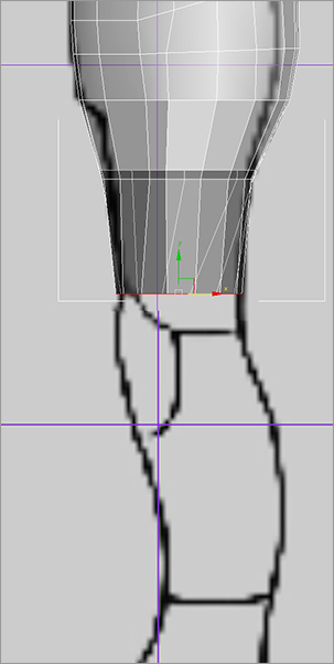
5. Select the D-shaped border edge and Shift + Move down on the Z-axis to extrude the upper thigh downward to right above the knee pad, as in Figure 6-35 (left). The knee pad’s position can be better seen in the side reference image plane shown later in Figure 6-37. Don’t worry; you will adjust the shape to fit the thigh later.
6. With the D-shaped border still selected, choose Graphite Modeling Tools Ribbon ⇒ Geometry (All) ⇒ Cap Poly to cap the end of the thigh stump. Select the new poly and choose Graphite Modeling Tools Ribbon ⇒ Polygons ⇒ GeoPoly to make the end of the thigh a more even shape; see Figure 6-35 (middle).
7. Select the thigh’s end polygon, and scale on the X-axis as shown in Figure 6-35 (right) to create a more oval shape. Then delete the cap so the bottom of the leg is open once again.
Figure 6-35: Creating the upper thigh
8. In the Front viewport, switch to Vertex mode, and scale and move the vertices on the leg to match the image plane. Check the Side viewport and shape the thigh as needed. Notice the bottom of the geometry should be located at about the top of the knee pad. Pop back into the Perspective viewport often as you work on these vertices to make sure some of the vertices are not being accidentally moved where they should not be. Figure 6-36 shows the front of the leg and Figure 6-37 shows the side of the leg.
Figure 6-36: Front view of leg

Figure 6-37: Side view of the leg
Make Adjustments as You Go
Feel free to adjust and smooth out your model by moving vertices as you progress through the tutorial. Little tweaks here and there may be necessary to keep the form fitting the intended character; use the image planes as guides to fit the geometry.
9. On the inside of the groin area where you created the four-segment bridge in step 4, move the edges as needed to make sure the segments are evenly spaced, as shown in Figure 6-38. This step should be repeated throughout the tutorial; keeping edges evenly spaced ensures that the model is organized and clean, and prevents polygons from penetrating each other.
10. Switch to Border mode and select the border opening at the bottom of the leg. Then use the Extrude Border method (hold Shift + Move), to extrude the leg down to the ankle as shown in Figure 6-39 (left).
Figure 6-38: Keep the edges in the groin area evenly spaced.
Figure 6-39: Extrude down to the ankle, SwiftLoop three new loops, and fit the new edges to the image plane.

11. Choose Graphite Modeling Tools Ribbon ⇒ Edit ⇒ SwiftLoop and create three new horizontal segments around the leg as shown in Figure 6-39 (middle). Then fit the vertices to the shape of the soldier’s leg in the side image plane in the Right viewport, as shown in Figure 6-39 (right). Go into the Front viewport and do the same to shape the leg properly.
12. In Border mode, select the ankle border as shown in Figure 6-40 (left) and Shift + Scale the border down on the Z- and Y-axes and in toward the center of the ankle, leaving a small hole; see Figure 6-40 (middle). Then switch to Vertex mode and select the vertices around the resulting small hole, and use Weld (Graphite Modeling Tools Ribbon ⇒ Vertices ⇒ Weld) to bring the vertices together; see Figure 6-40 (right). Adjust the Weld Threshold setting as needed to weld these vertices together.
Figure 6-40: Closing the ankle’s hole

Fixing Up the Body
Continue with the previous exercise’s scene file, or open the Soldier_V04.max scene file in the Scenes folder of the Soldier project from the companion web page.
1. The pelvis looks a bit funky. We need to streamline the mesh by combining some edges together. Select the vertical edges at the waist (select a single vertical edge and use Graphite Modeling Tools Ribbon ⇒ Modify Selection ⇒ Ring); see Figure 6-41.
2. Right-click to bring up the Quad menu. In the upper-left Quad, in the Tools 1 section, use Collapse, as shown in Figure 6-42. This will bring the two horizontal edge loops at the top and bottom of the selected vertical edges together into one edge loop.
3. In the Perspective viewport, use Orbit (use the ViewCube or Alt + MMB) to adjust the view to see under the groin area. In Edge or Vertex mode, move the segments to round that section out, as shown in Figure 6-43.
Figure 6-41: Select waist edges and use Ring to prepare for Collapse.

Figure 6-42: Use the right-click Quad menu to access Collapse.

Figure 6-43: Round out the edges in the groin area.

Figure 6-44: The leg with good edge spacing

4. In the Perspective viewport, use Orbit again around the leg and look for any spikes or pinches that may have occurred in the model. The goal is to split the difference between edges so that they’re as close to 50 percent from another edge as possible.
Keep in mind that a joint edge, such as the edges that make up the knee or elbow, need to stay where they are. Figure 6-44 shows the leg with good edge spacing. Take a moment to go back through the model and tweak the rest of it until you feel it is right. When modeling for animation, the mesh flow is an important factor.
Completing the Main Body
Continue with the previous exercise’s scene file, or open the Soldier_V05.max scene file in the Scenes folder of the Soldier project from the companion web page.
To create the other half of the model we are going to use the Mirror tool. The Mirror tool works off your character’s current pivot point. We want to mirror on the X-axis, so the gizmo needs to be in the dead center of our to-be-completed character (at the left side of the half model in the Front viewport); you will take care of that in step 1 of the following exercise.
In Chapter 5, when we built the Red Rocket, we used a modifier called Symmetry. This mirror technique gives the same results but in a different way. We will mirror the soldier’s body in the following steps:
1. In the Front viewport, select the model. Go to the Command panels to the right of the interface and, under the Hierarchy tab, select Affect Pivot Only (Figure 6-45). If you cannot find the gizmo, click on Center to Object under Alignment in the Command panel. This will pop the gizmo to the center of the model. We want the pivot on the left edge of the model so it’s in the center of the torso when it’s mirrored. With Affect Pivot Only, use the Move tool to move the gizmos to the left edge of the geometry, as shown in Figure 6-46.
Figure 6-45: Affect Pivot Only

2. Toggle off Affect Pivot Only. Select all the inside vertices and go to the Modeling ribbon ⇒ Align ⇒ X, this will move all the vertices to line up along the X-axis.
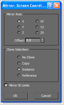
3. In the Main toolbar, click the Mirror button (![]() ) to bring up the Mirror dialog box. Select Mirror Axis X and Instance under Clone Selection, shown in Figure 6-47. Then click OK.
) to bring up the Mirror dialog box. Select Mirror Axis X and Instance under Clone Selection, shown in Figure 6-47. Then click OK.
Figure 6-46: Move the pivot point to the edge of the geometry.
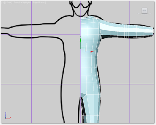
Figure 6-47: Mirror dialog box
With the mirror set to Instance, we can make some minor changes to the model before we combine the two sides more permanently. For example, in the next step we will move to the neck area where we will extrude out edges on one side, and see the mirrored side do the same on the other side.
4. In Edge mode, select the edges at the top of the right side of the torso geometry as shown in Figure 6-48 (left image) and Shift + Scale them on the X- and Y-axes to extrude the top of the shoulders toward the neck. With those edges still selected, Shift + Scale again to extrude another set of polygons toward the center neck as shown in Figure 6-48 (middle image). The edges all scale in toward the middle of the shoulder area and not the center of the neck at the spine, so switch to Vertex mode and move the vertices to better match the shape shown in Figure 6-48 (right image).
Figure 6-48: Drag out the edges around the neck.
5. Go back to Edge mode and select the same inner neck edges again, and extrude-move them (Shift + Move method) down to create a lip downward into the torso. Release the mouse, and then click again to Shift + Move in toward the center of the model to create a cap at the neck area (as shown in Figure 6-49). You can see the original model half is in X-Ray mode (Alt + X), while the mirrored instanced half mimics what you do to the original part.
Figure 6-49: The original model is in X-Ray mode, while the mirrored instance is solid.
Now, go through one last time and fix any edge spacing issues or wonky geometry you may have. It’s easier to do it now since your actions will be mirrored to the other side. You can always fix things later, but then you’ll just have to do them twice, once for each side of the model. When you’re ready we are going to combine and weld the two parts of the model together.
To un-instance the instanced side of the model, select it and go to the Modify panel. In the toolbar under the Modifier Stack, click on the Make Unique icon (![]() ). Now the two instances are two copies and are no longer mirroring each other.
). Now the two instances are two copies and are no longer mirroring each other.
6. Select the right half, and then select Modeling ribbon ⇒ Geometry (All) ⇒ Attach and select the other side of the model; this will combine both halves.
We are not done, however; the vertices in the center of the model are not welded together yet! They might look like it, but they are indeed separate sets of vertices running down the seam where the two halves attach. We need to keep this model solid to prevent the mesh from tearing apart during animation:
7. Enter the Front viewport and switch to Vertex mode. Marquee a selection box down the center of the torso model to select the vertices along the seam of the two halves. Make sure Ignore Backfacing is off, then select Modeling Ribbon ⇒ Align, and click on the X. This will align vertices along the X-axis.
8. With the vertices selected, choose Modeling ribbon ![]() ) to open the Weld caddy. Notice that there is a before and after count on the Weld caddy that pops up in the viewport. Increase the Weld Threshold setting until something visibly changes in the viewport, then reduce the value slightly to undo the change. Feel free to go into the Perspective viewport to check this. Weld the vertices together by pressing the OK (check mark) button.
) to open the Weld caddy. Notice that there is a before and after count on the Weld caddy that pops up in the viewport. Increase the Weld Threshold setting until something visibly changes in the viewport, then reduce the value slightly to undo the change. Feel free to go into the Perspective viewport to check this. Weld the vertices together by pressing the OK (check mark) button.
Creating the Accessories
Continue with the previous exercise’s scene file, or open the Soldier_V06.max scene file in the Scenes folder of the Soldier project from the companion web page. Most of the smaller detail in the model will be added through textures; however, it helps tremendously to add detail, such as pouches and elbow and knee pads, into the actual geometry. This creates a better silhouette for your character. These details are further enhanced with textures in Chapter 7, “Materials and Mapping.”
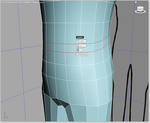
1. To create the belt we’re going to chamfer and extrude an edge loop that’s located closest to the belt line on the model. Select an edge at the belt line, then choose Graphite Modeling Tools Ribbon ⇒ Modify Selection ⇒ Loop, as shown in Figure 6-50.
2. With the edge loop selected, select Modeling ribbon ⇒ Edges ⇒ Chamfer ⇒ Chamfer Settings with an Edge Chamfer Amount of 1.5, as shown in Figure 6-51.
Figure 6-50: Select and then Loop the edges at the belt area.
Figure 6-51: Chamfer setting for the belt
3. With the two edges from the chamfer still selected, hold Shift and click Graphite Modeling Tools Ribbon ![]() ). This will select the polygons associated with the two selected edges. Next, choose Graphite Modeling Tools Ribbon ⇒ Polygons ⇒ Extrude ⇒ Extrude Settings, and make sure you extrude by local normal with a Height of 0.5, as shown in Figure 6-52.
). This will select the polygons associated with the two selected edges. Next, choose Graphite Modeling Tools Ribbon ⇒ Polygons ⇒ Extrude ⇒ Extrude Settings, and make sure you extrude by local normal with a Height of 0.5, as shown in Figure 6-52.
Figure 6-52: Extrude polygons for the belt.

4. Next we’re going to block out a pouch on the belt. Delete two sections of the belt on the body’s left side, as shown in Figure 6-53.
5. Select the four polygons above and below the deleted area (also shown in Figure 6-53). Select Modeling ribbon ⇒ Polygons ⇒ Extrude ⇒ Extrude Settings, set an amount of 0.5, then click + to apply one extrusion, and then press OK for a second extrusion and to exit the caddy. The pouch is now extruded twice for a total extrusion depth of 1, as shown in Figure 6-54
Figure 6-53: Delete the belt polygons on the left side of the belt. Then select the indicated polygons for the next step.

Figure 6-54: Extruded pouch polygons

6. Select the four polygons on top of the bottom half of the pouch, and the four polygons on the bottom of the top half of the pouch, as shown in Figure 6-55, and delete them. The figure shows the model in See-Through mode (Alt + X) to see all eight polygons to be selected and deleted.
Figure 6-55: Select and delete polygons.

7. In Edge mode, select the top and bottom edges around the newly deleted areas and use Bridge to create polygons in between (Graphite Modeling Tools Ribbon ⇒ Edges ⇒ Bridge) to close the gap between the two pouch halves.
The pouch should look like a box; if it doesn’t, move vertices around so it does. Once the pouch has the correct shape, move the top level of polygons further out away from the belt to give the pouch more depth. It should look something like the model in Figure 6-56.
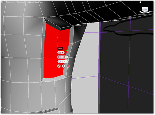
8. To create some depth to the vest that our character will be wearing, you will want to cut out a level of clothing under the arms. Select two columns and three rows of polygons directly underneath the armpit, as shown in Figure 6-57.
9. Choose Graphite Modeling Tools Ribbon ⇒ Polygons ⇒ Bevel ⇒ Bevel Settings and, in the caddy, use a Height of -0.5 and an Outline of -1.0, as shown in Figure 6-58.
Figure 6-56: Finished pouch
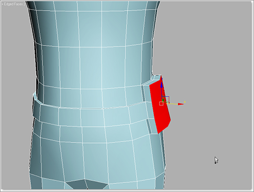
Figure 6-57: Select the polygons directly under the armpit.

Figure 6-58: Bevel the selected polygons.
Adjust any vertices as necessary for an even and smooth look. Do the same for the other side of the model. The final appearance of the area underneath the armpit is seen in Figure 6-59.
Figure 6-59: Final appearance of the area under the arm

10. Next, we’re going to add a leg strap to hold a gun holster. Choose Graphite Modeling Tools Ribbon ⇒ Edit ⇒ SwiftLoop, and add a new horizontal loop of edges below the groin area on both legs. When the loop is created it is crooked, but we need the new edges to be straight. So, after you create the edge, hold Ctrl + Alt and click and drag on the new edge to straighten it. The SwiftLoop tool should still be active, as shown in Figure 6-60.
11. On the right leg, in Edge mode, select one edge of the new edge loop you created in the previous step. Select Modeling ribbon ⇒ Modify Selection ⇒ Loop, then Graphite Modeling Tools Ribbon ⇒ Edges ⇒ Chamfer ⇒ Chamfer Settings and enter an Edge Chamfer Amount of 1.5 and press OK.
12. Then in Polygon mode, select the loop of new polygons (hold Shift and click on the polygon icon in the Graphite Modeling Tools Ribbon ⇒ Polygon Modeling) and select Modeling ribbon ⇒ Polygon ⇒ Extrude ⇒ Extrude Settings, using a Height of 0.4, as shown in Figure 6-61, to pull out the strap.
Figure 6-60: SwiftLoop
Figure 6-61: Extrude polygons.

Figure 6-62: Delete polygons.

13. In Polygon mode, select a strip of polygons that goes from the top of the leg strap to the bottom of the belt, and delete them. This is shown in Figure 6-62.
14. Select the edge at the leg strap and at the belt, and use Bridge to create the polygons needed to fill out the strap, as shown in Figure 6-63. The sides of the holster are still open.
15. Now select the edges between the new bridged polygons and the model’s hip, then use Bridge again in this area, as shown in Figure 6-64. Make sure to repeat this on the other side of the holster also.
16. To finish the gun holster, go into the Right viewport and create a plane with these parameters as shown in Figure 6-65—Length: 20, Width: 7, Length Segs: 4, Width Segs: 1.
17. Convert the plane to an Editable Poly. Position the place where the holster will be and in Vertex mode, shape it as shown in Figure 6-66.
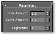
18. In the Modify panel ⇒ Modifier List, add a Shell modifier to the plane and give it the following parameters (seen in Figure 6-67): Inner Amount: 1.2, Outer Amount: 1.2, Segments: 1. Fit this piece in place on the vertical leg strap you created.
19. Select the body now and select Modeling ribbon ⇒ Geometry ⇒ Attach and click on the gun holster.
Whew! Now it is time to work a bit on your own. Follow the previous steps to create any additional pouches or straps you may want on your model. We added one more pouch, about half the size of the first one, on the front right side of the model. Keep in mind, any changes you make to the design of the book’s model will make your model differ from the one we use for texturing in Chapter 7.
Figure 6-63: Use Bridge to create polygons to fill out the strap.
Figure 6-64: Use Bridge to fill the gap on the side of the strap.
Figure 6-65: Plane parameters for the gun holster
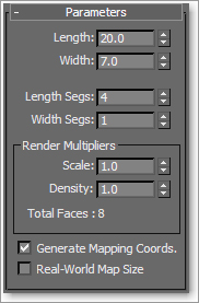
Figure 6-66: Shape the plane into a holster shape.
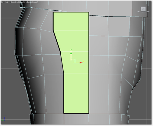
Figure 6-67: Shell modifier parameters
Using the tools to create the belt and pouches, you can easily create geometry for knee pads and elbow pads. Refer to the beginning of the “Creating the Accessories” section if you need a refresher on how to do this. You can see the completed body in Figure 6-68.
Figure 6-68: Completed body with new belt pouch, knee pads, and elbow pads

Putting On the Boots
Continue with the previous exercise’s scene file, or open the Soldier_V07.max scene file in the Scenes folder of the Soldier project from the companion web page. At this point in the tutorial, you are probably feeling more comfortable with the tools and interface. For this next part of the tutorial we are going to be more efficient with the descriptions and directions given unless the procedures are new to this chapter.
1. To create the boots start by creating a cylinder in the Perspective viewport. Select the Create panel ⇒ Geometry ⇒ Cylinder. The parameters are shown in Figure 6-69. Select the cylinder and Convert to Poly, then position it under the left leg to be the top part of the boot.
Figure 6-69: Cylinder parameters

2. Using the Right viewport, move vertices on the cylinder so the shape mimics the form of the boot in the image plane. Delete the topmost and bottommost polygons that were created with the cylinder.
3. Ignore the two bottom front edges of the cylinder where the top of the foot would be, and select the bottom U-shaped edges of the cylinder. Extrude (Shift + Move method) the edges of the back half of the boot top to the bottom of the foot in the image plane, as shown in Figure 6-70.
Figure 6-70: Using Extrude Edge to create another set of polygons for the U-shaped back and side part of the boot
4. Select the two bottom-front edges that you ignored previously, and extrude-move them (Shift + Move method) four times to form the extruded polygons to the image plane as shown in Figure 6-71. You will need a total of four rows of polygons for the top of the foot. As you extrude, you can simply release the mouse button after one extrusion, and then Shift + Move again for the next extrusion. Repeat for a total of four new strips of polygons, as shown in Figure 6-71. Form the new polygons as needed to fit the top of the foot.
5. In Edge mode, select the vertical edges on either side of the gap as shown in Figure 6-72 (left). Then choose Graphite Modeling Tools Ribbon ⇒ Edges ⇒ Bridge ⇒ Bridge Settings and enter three segments and bridge the gap. Repeat the same on the opposite side of the foot.
6. Then switch to Vertex mode, and choose Graphite Modeling Tools Ribbon ⇒ Vertices ⇒ Weld to fuse together the vertices, also shown in Figure 6-72 (right).
7. Select Modeling ribbon ⇒ Edit ⇒ SwiftLoop, and create a new horizontal edge loop around the foot from heel to toe on the side of the foot, as shown in Figure 6-73.
Figure 6-71: Using Extrude Edge to create three new polygons that form with the image plane for the top of the foot

Figure 6-72: Use Bridge to fill the gap and Weld to close the gaps.
Figure 6-73: Use SwiftLoop to add a horizontal loop around the boot.

The eight segments we defined on the original boot cylinder are not enough, so we need to create more segments for the cylinder.
8. In Edge mode, select the middle vertical edge of the foot, and use Loop. Then select Modeling ribbon ⇒ Edges ⇒ Chamfer ⇒ Chamfer Settings, and enter the caddy parameters shown in Figure 6-74.
9. Follow the same process to chamfer the very back vertical edge on the boot (running just below the calf) and use the added vertices to round out the heel. The top of the foot is a bit boxy, so scale in the vertices and smooth out the sides as in Figure 6-75.
Adjusting as You Go
Remember to always adjust vertices to fit the form on the image plane, or use your own artistic license as to what you think looks best. If you do make your own modifications, keep in mind that we will texture this soldier in the next chapter, and the UV layout and painted maps we use may not fit any adjustments you make to your own design of the model.
When you are happy with how this looks, center the pivot to the boot model and mirror it on the X-axis as a copy (not an instance). You can then attach the boots to the rest of the body, as you did with the gun holster. The two completed boots, now attached to the body, can be seen in Figure 6-76.
Figure 6-74: Chamfer the middle edge loop.
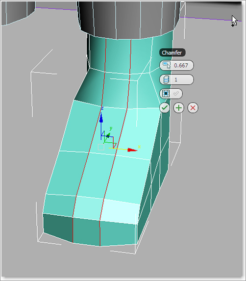
Figure 6-75: Smooth out the sides of boot.
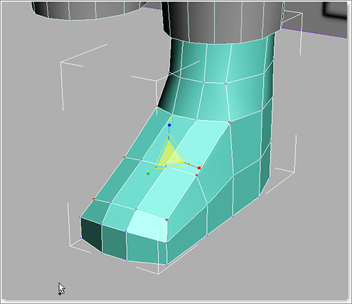
Figure 6-76: Boots completed and attached to the body

Creating the Hands
Continue with the previous exercise’s scene file, or open the Soldier_V08.max scene file in the Scenes folder of the Soldier project from the companion web page. In this section, we will create simple hands for the soldier. For this model we don’t need finger manipulation, so any hand detail will be taken care of in textures. Instead, we’re going to create a mitten for the soldier’s hand.
1. To create one of the hands, start with a box. Create a box primitive in the Perspective viewport, and then in the Modify panel, change its parameters, as shown in Figure 6-77. Position the box in your Top viewport over the wrist. Finish positioning it in the Front viewport and convert it to an Editable Poly.
Figure 6-77: Box primitive parameters

2. In the Top viewport, use SwiftLoop to create two segments vertically and two segments horizontally. Then, in Vertex mode, move the vertices to create a mitten arc as shown in Figure 6-78.
3. With the hand selected, go into Polygon mode and select the polygons on the hand where the wrist and the arm meet, and delete them. Figure 6-79 shows the hollow hand.
4. In Edge mode, select the outer edge loop on the top and bottom of the hand. Then go to Graphite Modeling Tools Ribbon ⇒ Edges ⇒ Chamfer, with an amount of 0.7 as shown in Figure 6-79.
5. Use SwiftLoop to create an edge up from the wrist, as shown in Figure 6-80.
Figure 6-78: Reshape vertices to create a mitten shape.

Figure 6-79: Chamfer the top and bottom edge of the hand.

Figure 6-80: Use SwiftLoop to create an edge at the wrist.

6. In Polygon mode, select the three polygons just up from the newly created edge on the side of the hand, where the thumb should be. Select Modeling ribbon (![]() ), and click the Y-axis option in the Align orientation (Local) area and click OK. Then move the corner edges in to round out the beginning shape of the thumb (see Figure 6-81).
), and click the Y-axis option in the Align orientation (Local) area and click OK. Then move the corner edges in to round out the beginning shape of the thumb (see Figure 6-81).
Figure 6-81: Begin to shape the thumb.

7. Now bevel the polygons at the end of the thumb for the knuckle. Select Modeling ribbon ⇒ Polygons ⇒ Bevel ⇒ Bevel Settings, using the values shown in Figure 6-82.
8. Repeat step 7 at the tip of the thumb geometry to create another segment for the thumb from the knuckle to the tip of the thumb, as shown in Figure 6-83. Adjust the polygons, vertices, and edges to get the thumb to look like Figure 6-84.
9. Select the polygon at the ends of the thumb and fingers. Turn on Use Soft Selection—Graphite Modeling Tools Ribbon ![]() )—and in the Front viewport, move down the thumb and fingers to give them a slight slope, as shown in Figure 6-85.
)—and in the Front viewport, move down the thumb and fingers to give them a slight slope, as shown in Figure 6-85.
10. In the Perspective viewport, scale the wrist down to fit within the sleeve if necessary. Center the pivot to the model, and mirror it as a copy for the other side. Place the hands at the wrists and attach them to the rest of the model. The final gloved hand is shown in Figure 6-86.
Figure 6-82: Bevel settings
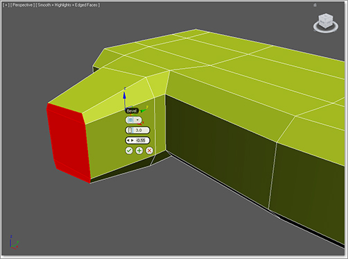
Figure 6-83: Move, rotate, and scale the polygons to shape in the thumb.
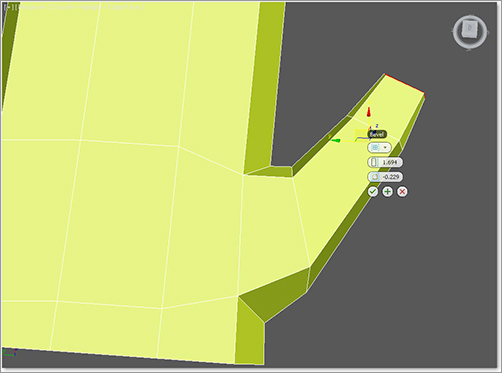
Figure 6-84: Thumb with all its joints
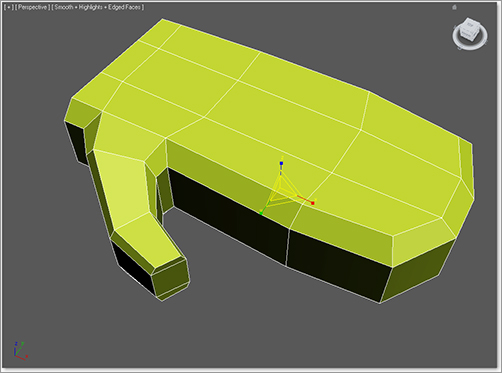
Figure 6-85: Give the thumb and fingers a slight slope downward.
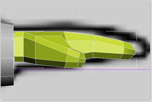
Figure 6-86: Final glove
Creating the Head
Continue with the previous exercise’s scene file, or open the Soldier_V09.max scene file in the Scenes folder of the Soldier project from the companion web page.
The soldier’s head will consist of four parts: a helmet, goggles, a face mask, and a head shape for them to sit on. The easiest way to create and fit these components is to start with the head shape. First, though, we need to adjust the body’s neck line so it’s a bit better to work with. Right now the neck area is close to a circle shape. We want this to be closer to an oval that follows the contour of the rest of the model.
1. In Polygon mode, select the front of the neck line, turn on Use Soft Selection—Graphite Modeling Tools Ribbon (![]() ). Then adjust the falloff of the soft selection in the Graphite Modeling Tools Ribbon ⇒ Soft tab, and change the Falloff value to 4.0. Now move the polygons down on the Y-axis as shown in Figure 6-87. Do the same for the back of the model, as in Figure 6-88. These actions will smoothly create a lower neck line, giving more definition to the shoulders as well.
). Then adjust the falloff of the soft selection in the Graphite Modeling Tools Ribbon ⇒ Soft tab, and change the Falloff value to 4.0. Now move the polygons down on the Y-axis as shown in Figure 6-87. Do the same for the back of the model, as in Figure 6-88. These actions will smoothly create a lower neck line, giving more definition to the shoulders as well.
2. Create a Cylinder with the parameters shown in Figure 6-89. Convert it to an Editable Poly and position the cylinder inside the neck line as shown in Figure 6-90.
3. Once again we will model half of each part and then mirror it to save time. Delete the left half, the top, and the bottom of the cylinder, and move the edges and vertices so it’s formed better within the neck line, as shown in Figure 6-91.
Figure 6-87: Soft select the polygons at the front of the neck and move them down.
Figure 6-88: Repeat on the polygons on the back of the neck.
Figure 6-89: Cylinder parameters

4. Now select the top edges of the cylinder and use the Extrude Edge (Shift + Move method) method to create another level of polygons. The neck now has two rows of polygons. Then, select the first edge on top nearest where the Adam’s apple would be, and use Extrude Edge (Shift + Move method) to create a new polygon. Move the edge up along the Z-axis, as shown in Figure 6-92.
Figure 6-90: Position the cylinder inside the neck area.

Figure 6-91: Delete half of the cylinder and its top and bottom.
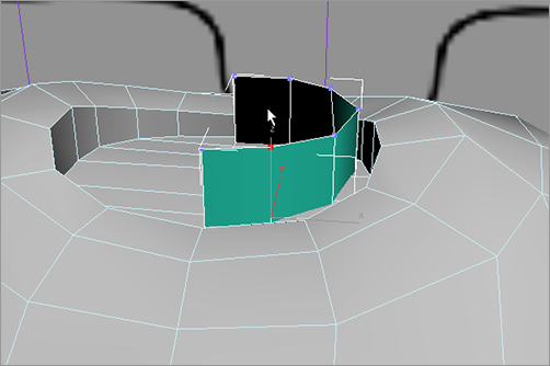
Figure 6-92: Begin the creation of the neck with Extrude.

Outlining the Head
In the following steps, we will create an outline of the head by creating one strip of polygons and then forming them to the side image plane. We will extrude 15 times total, and move the edges to create the general form of a head. Be sure to keep the outer edge of the head inside the edges of the image plane; this allows room to fit the head accessories.
5. You should still have the edge selected from the last step. Use Extrude Edge (Shift + Move method) from the previous step, but when you finish one polygon, release the mouse button, then click again and move the edge to create another extruded polygon. You will do this 14 more times, following the form of the head in the image plane, as shown in Figure 6-93.
6. In the Front viewport, select the edge on the top base of the neck about where the ear might be. Use Extrude Edge (Shift + Move method) and position a polygon strip as we did in Step 5, but this time for the side of the head. Extrude a total of five segments up from the neck. Also in Edge mode, use Bridge (Graphite Modeling Tools Ribbon ⇒ Edges ⇒ Bridge) to fill the gap between the side of the head and the nearest edge on the top of the head, as shown in Figure 6-94.
Figure 6-93: Create the head outline using the Shift + Move method, following the image plane.

7. To build out the front of the face, start by selecting the two edges just under the chin and use Extrude Edge (Shift + Move method) to extrude them out to the right, as shown in Figure 6-95. In Vertex mode, select Modeling Graphite Modeling Tools Ribbon ⇒ Vertices ⇒ Target Weld. To use Target Weld you click on one vertext and drag a line to the other to fuse the vertices together. So first click the vertex on the new polygon closest to the neck, and then click on the neck vertex, shown in Figure 6-95. This will fuse the new polygons for the jowls to the neck.
8. Back in Edge mode, select the two rightmost edges of the polygons we just created for the jowls, then use Extrude Edge (Shift + Move method) to extrude those edges up on the Z-axis. Match the number of segments with the segments on the outer head strip we already created. This is shown in Figure 6-96.
9. Select the edges shown on the left side of Figure 6-97. Use Bridge (Graphite Modeling Tools Ribbon ⇒ Edges ⇒ Bridge) to curve the strip toward the forehead, as shown in Figure 6-97.
Figure 6-94: Creating polygons for the side of the head

Figure 6-95: Extrude edges to the right and weld the neck vertices.

Figure 6-96: Extrude a new strip; match the segments.
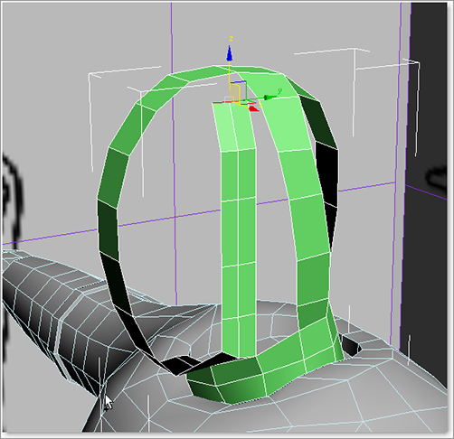
Figure 6-97: Use Bridge to close the gap.

10. As we did in step 9, in Edge mode, use Extrude Edge (Shift + Move method) to extrude another row of polygons in toward the front of the face. Then in Vertex mode, use Target Weld on either side of the front face strip, as shown in Figure 6.98.
11. Looking at the ring of edges from the front of the strip of the head to the side of the head, it’s clear we don’t have enough horizontal edges. Select the edge closest to where the bridge of the nose would be, then use Chamfer (Graphite Modeling Tools Ribbon ⇒ Edges ⇒ Chamfer Settings ⇒ Chamfer Settings) with an amount of 1.346, then press OK. Try to keep the edges equally spaced, as shown in Figure 6-99.
Figure 6-98: Use Extrude Edge, then Target Weld the vertices.
Figure 6-99: Chamfer the edge that falls at the bridge of the nose.

12. Select the four edges from the front of the face to the side of the face, and then use Bridge, as shown in Figure 6-100. Notice that there is nowhere to weld to on the vertical edge on the top of the head. We need to create another edge running down the front of the face and then weld the vertices together to close the head.
13. Choose Graphite Modeling Tools Ribbon ⇒ Edit ⇒ Cut to enter the Cut tool. Then cut from the dead end edge at the top of the head down to the bottom of the neck, as shown in Figure 6-101. Make sure you start and end the cut directly on the vertices.
14. Then, in vertex mode, select the two vertices at the top of the cut, go to Graphite Modeling Tools Ribbon ⇒ Vertices ⇒ Weld and change the Weld Threshold setting until the two vertices are welded together.
Figure 6-100: Select edges and use Bridge.
Figure 6-101: Cut the new edge.

Rounding Out the Face
Figure 6-102: Take some time to round out the face.

Take some time to round out the face a bit as shown in Figure 6-102. The face doesn’t have to be perfectly round, but it will help if the face is close to a round shape. The majority of the head mesh we will create will be covered with the goggles, helmet, and face mask. However, we can use the geometry we create to fit and form those accessories.
15. In Edge mode, select the edges around the ear and use Bridge (Graphite Modeling Tools Ribbon ⇒ Edges ⇒ Bridge) as shown in Figure 6-103.
Figure 6-103: Bridge edges.

16. Looking at the back of the head, you can see an edge open on the bottom. Use the Cut tool to add another vertical edge, as shown in Figure 6-104.
17. Select the edges on the inside of the gap closest to the back of the head and use Extrude Edge (Shift + Move method) to extrude more faces toward the ears as shown in Figure 6-105. Then switch to Vertex mode and use Target Weld to weld the loose vertices at the top and bottom, also shown in Figure 6-105.
Figure 6-104: Create a new edge for the back of the head/neck using the Cut tool.

Figure 6-105: Extrude edges and use Target Weld on the loose vertices.

Creating the Back of the Head
We have the same problem with the back of the head as we did with the front of the face. There are not enough horizontal edges.
18. Chamfer a horizontal edge near the top of the back of the head, as shown in Figure 6-106. In Figure 6-106, we can visualize how the polygons will bridge over. In this case, after we create the chamfer, we will have five segments that can bridge in the next step.
19. Bridge the vertical edges of the hole; you can see that completed in Figure 6-107. This time we have the exact amount needed to create a solid head shape.
20. Go into the Right viewport and notice how the edges are closer to the front of the head than the back of the head, as shown in Figure 6-108 (left). Select and move edges or vertices until the vertices are more evenly spaced, as shown in Figure 6-108 (right).
Figure 6-106: Chamfer edges.

Figure 6-107: Bridge the vertical edges to fill the last hole.
Figure 6-108: Move edges or vertices to evenly space the edges.

Mirroring the Head
Now make any necessary adjustments to your mesh to get it just right. Again, it’s not terribly vital that this part be perfect because we will cover it up with accessories in the steps ahead. Once you’re satisfied continue with the following steps:
21. Adjust the head’s pivot to the left edge of the geometry and mirror the half over on the X-axis as a copy, as shown in Figure 6-109.
Figure 6-109: Mirror the head halves.

22. Select Modeling ribbon ⇒ Geometry ⇒ Attach, and then select the other side of the head to attach them together. Now in Vertex mode, select all the vertices in the center vertical seam of the head, and choose Graphite Modeling Tools Ribbon ⇒ Vertices ⇒ Weld ⇒ Weld Settings. Turn the Weld Threshold up a bit to be sure all the vertices are welded when you click OK.
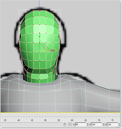
23. Going into the Front viewport we can see our head is a little wide compared to the image plane. Scale it just a bit to fit on the X-axis so we have room to put on the helmet. (See Figure 6-110.) Our base head is complete; now we can add the details.
Figure 6-110: Scale the head on the X-axis to make room for the helmet.
Merging in and Attaching the Head’s Accessories
The remaining accessories for the soldier are the helmet, goggles, and face mask. To create these we would repeat the same methods we have already covered, so we’ll cut a little time and merge in the finished pieces.
The finished models for the helmet, goggles, and face mask have been created separately and can be merged into your final model. The process is the same as the one used in Chapter 5 for the Red Rocket project. Keep in mind that if you changed the design of the soldier as you built him in your scene, the accessories for the head may not fit perfectly. If this is the case, you may wish to use the scene file provided.
Continue with the previous exercise’s scene file, or open the Soldier_v10.max scene file in the Soldier project’s scenes folder from the companion web page.
Figure 6-111: Merge dialog box

Figure 6-112: Warning
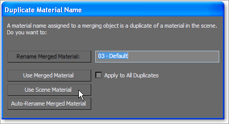
1. Click the Application button ⇒ Import ⇒ Merge and, from the Merge File dialog box, choose the file Soldier_Accessories.max in the Scenes folder of the Soldier project from the web page, then click Open. From the Merge dialog box (see Figure 6-111), select all the objects in the list, and click OK. You might see a warning about materials (see Figure 6-112), so just click Use Scene Material. The object will appear in the scene, lined up with the model.
The next step is that we need all the accessories to be attached to the main body. This means the entire soldier model is a single mesh and is for the purpose of creating the UVW mapping for the model in Chapter 7.
2. Select the body and Select Modeling ribbon ⇒ Geometry (All) ⇒ Attach ⇒ Attach from List to open the Attach List dialog box. This makes it easier to attach when you have multiple objects to attach.
3. Because we selected the body when we went into the Attach List dialog box, the window won’t show the body as an object that we can select. Select the four objects in the list and click Attach.
The soldier is complete! Well, at least the model. Now that the head objects are attached to the body, they cannot be selected individually. As a matter of fact, the entire soldier is one object, from the boots to the helmet. You have to select the boots, hands, or any accessories we added to the model by using Element mode from the Modifier Stack. We will see this point in action in the next chapter as we lay out UVs for the soldier.
Go grab a beverage; you’ve earned it!
By now you have had a lot of exposure to, and a lot of experience with, modeling with 3ds Max. You will find that the more you model, the easier the process becomes, and the more detailed and finessed your models will turn out.
This chapter explored and explained several tools used in modeling, organic or otherwise. From a simple box, a torso was formed to match the general shapes shown in the reference images. The arms and legs were extruded and shaped. Using Mirror required you to model only half of the soldier character at a time. The head modeling came next and then you merged in already completed accessories from another scene file to add detail to the model’s head.
Although we used a fairly low-polygon count soldier character here, this toolset can be utilized for any type of model.