
Chapter 11
3ds Max Rendering
Rendering is the last step in creating your CG work, but it is the first step to consider when you start to build a scene. During rendering, the computer calculates the scene’s surface properties, lighting, shadows, and object movement, and then it saves a sequence of images. To get to the point where the computer takes over, you’ll need to set up your camera and render settings so that you’ll get exactly what you need from your scene.
This chapter will show you how to render your scene using 3ds Max’s scanline renderer and how to create reflections and refractions using raytracing. In addition, this chapter will introduce you to the popular mental ray renderer and HDRI lighting workflow.
Topics in this chapter include the following:
- Rendering setup
- Motion blur
- Previewing with ActiveShade
- Cameras
- Safe Frame
- Render elements
- Rendering effects
- Raytraced reflections and refractions
- Bringing it all together: Rendering the rocket
- mental ray Renderer
- Final Gather with mental ray
In a manner of speaking, everything you do in CG can be considered setup for rendering. More specifically, your render settings and what final decisions you make about your 3ds Max scene ultimately determine how your work will look. In many ways, you should be thinking about rendering all along—especially if you are creating 3D assets for a game, where the 3D scenes are rendered in real time by the game engine. If you create models and textures with the final image in mind and gear the lighting toward elegantly showing off the scene, the final touches will be relatively easy to set up.
To set the proper settings, begin with the Render Setup dialog box.
Render Setup Dialog Box
Figure 11-1: The Common tab in the Render Setup dialog box

The Render Setup dialog box is where you define your render output for 3ds Max. You can open this dialog box by clicking the Render Setup icon (![]() ) in the Main toolbar, by selecting Rendering (
) in the Main toolbar, by selecting Rendering (![]() ) a frame in your scene to check your work. The settings in the Render Setup dialog box are used even when the Render button is invoked; so it’s important to understand how this dialog box works. Figure 11-1 shows the Common tab in the Render Setup dialog box.
) a frame in your scene to check your work. The settings in the Render Setup dialog box are used even when the Render button is invoked; so it’s important to understand how this dialog box works. Figure 11-1 shows the Common tab in the Render Setup dialog box.
Common Tab
The Render Setup dialog box is divided into five tabs; each tab has settings grouped by function. The Common tab stores the settings for the overall needs of the render—for example, image size, frame range to render, and type of renderer to use.
In the Common Parameters rollout, you will find the most necessary render settings. They are described in the following sections.
Time Output
In this section, you can set the frame range of your render output by selecting one of the following options (as shown in Figure 11-2):
Figure 11-2: Time Output sets the frame range of your render.
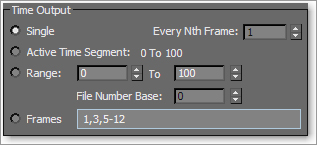
Single This option renders the current frame only. The frame range is set to Single by default.
Active Time Segment This option renders the frame range in the timeline.
Range This option renders the frame range specified in the text boxes.
Frames This option renders the frames typed in the text box. You can enter frame numbers separated by commas or specified as ranges, such as 3–13, to render only the specified frames.
Every Nth Frame This option is enabled when you are rendering more than one frame. It allows you to render every nth frame, where n is a whole number, so you can specify how many frames to skip.
Typically, you will be rendering single frames as you model, texture, and light the scene. The closer you are to final rendering, especially for scenes with moving cameras or lights, the more likely you will need to render a sequence of images to check the animation of the scene and how the lighting works. This is where the Every Nth Frame function comes in very handy. Using it, you can render every fifth frame, for example, to quickly see a render test range of your scene without having to render the entire frame range.
You should always test render at least a few frames of an animation before you render the entire frame range, because the smallest omission or error can cost you hours of rendering and effectively bottleneck production flow and get several people annoyed at you. This practice is a good habit to start. Whenever you want to launch a render of the entire scene, render at least one frame to check the output. If you have animated lights or cameras, use the Every Nth Frame option to test a few frames.
Area to Render This is where to go if you want to render only part of your frame. This is especially useful when you are testing the look of a single part of your frame, or even a single object, without having to wait for the rest of the frame to process. Here you can choose View, Selected, Region, Crop, or Blowup. For example, when set to Region, a re-sizeable box appears in your viewport as well as the Rendered Frame Window where you can select the region of the frame you wish to render.
Output Size
The image size of your render, which is set in the Output Size section (as shown in Figure 11-3), will depend on your output format—that is, how you want to show your render. Chapter 1, “Basic Concepts,” explains the popular resolutions used in production.
Figure 11-3: Output Size sets your output format size.
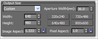
Resolution By default, the dialog box is set to render images at a resolution of 640 × 480 pixels, defined by the Width and Height parameters, respectively. This resolution has an image aspect of 1.333, meaning the ratio of the frame’s width to its height.
Image Aspect Ratio Changing the Image Aspect value will adjust the size of your image along the Height parameter to correspond with the existing Width parameter to accommodate the newly requested aspect ratio. Different displays have different aspect ratios. For example, regular television is 1.33:1 (simply called 1.33) and a high-definition (HD) television is a widescreen with a ratio of 1.78:1 (simply called 1.78). The resolution of your output will define the screen ratio.
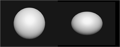
Pixel Aspect Ratio Pixel Aspect affects the image because it actually changes the shape of the pixel from a square to a rectangle. This reflects how TV screens (standard definition, not HD) display images. When output is displayed on a TV screen, the image will be squeezed slightly horizontally. Therefore, renders are created a bit wider so that when they are displayed on a TV screen, they will appear normal. This is especially visible when you render a round object, as shown in Figure 11-4. On the left, the sphere is rendered with a pixel aspect of 1.0 (i.e., a 1:1 ratio). On the right, the sphere is rendered with a pixel aspect of 0.9 (i.e., a 0.9:1 ratio). However, when the sphere on the right is displayed on a standard TV, it will appear round and not stretched in this manner.
Figure 11-4: Rendering a round object for display on a TV screen
You hardly ever have to worry about pixel aspect ratios. They are mentioned only for those who may be outputting directly to DV tape or DVD. Luckily, in the Output Size section of the Render Setup dialog box there is a drop-down menu for choosing presets from different film and video resolutions. Custom is the default, and it allows you to set your own resolution. You can also select one of the preset resolution buttons. For DVD or TV output, you should select the NTSC D-1 (video) preset. For output to a DV tape, you should select the NTSC DV (video) preset. They both have a pixel aspect ratio of 0.9 to account for the TV “squeeze.” Of course, if you (or your client) are in Europe or in another place where the PAL standard is used, you will need to select the PAL equivalents of the aforementioned presets, because TV resolutions and frame rates differ internationally. For more on aspect ratios and frame rates, see Chapter 1.
The higher the resolution, the longer the scene will take to render. Doubling the resolution might quadruple the render time. To save time when you’re working with large frame sequences, you can render tests at half the resolution of the final output and render every fifth frame or so.
The image quality of a render also affects how long a render will take. In addition to turning down the resolution for a test, you can use a lower-quality render and/or turn off certain effects, such as Atmospherics (volume lights, for example, that simulate light cutting through fog). Quality settings are explained in the following section.
Options
Figure 11-5: Options section gives you global toggles.

The Options section (shown in Figure 11-5) lets you access several global toggles. Three boxes are checked by default. You can toggle the rendering of specific elements in your scene. For example, if you are using Atmospherics (volume light) or Effects (lens flare) and don’t want them to render, you can uncheck the appropriate box(es). This is a shortcut to turn off the effect or atmosphere.
Render Output
Figure 11-6: The Render Output section is used to indicate the location and format of the image files.

What good does it do to render a scene if you don’t save the files? When you are done setting up the dialog box for your image output, you need to tell 3ds Max where to render the images and what file format to use. Use the Render Output section as shown in Figure 11-6 to indicate that the file should be saved.
The image format can be selected to be a single image file or sequence of image files that form a sequence, or it can be a movie file such as a QuickTime. In fact, 3ds Max supports many image file formats. The most common movie format is arguably QuickTime. A sequence of frames is typically rendered to Targa or TIFF files.
Choosing a Filename
To specify a location and file type to render to, click the Files button to open the Render Output File dialog box shown in Figure 11-7. Select the folder to which you want to render, and set the filename. You can set the file type using the Save As Type pull-down menu.
Proper file naming is very important when you render a scene, particularly when you are rendering a sequence of images and have hundreds of frames. Saved images are usually identified by a filename, a frame number, and an extension in the form filename_####.ext—for example, stillife_0234.tif. This format is used in production facilities and accepted by most compositing programs, such as Combustion or After Effects.
Figure 11-7: The Render Output File dialog box defines how the render saves to disk.
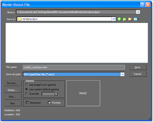
Figure 11-8: Image filenames without a separator between the filename and frame number are confusing to look at and might play out of sequence.

When you enter the filename for an image sequence, you can include an underscore (the _ character) after the filename and before the frame number to help differentiate the two. This is especially useful if you use version numbers in your scene names. If you don’t use an underscore (or similar character) between the filename and frame number, your rendered image files can be confusing, as shown in the file list in Figure 11-8.
It’s a good idea to name your rendered images according to the scene’s filename. This way you can always know from which scene file a rendered image was produced, without rooting through several files and/or guessing.
The extension portion of the image filename is a three-letter abbreviation that corresponds to the type of file you are rendering. By specifying a file format in the Save As Type drop-down menu, you automatically set the extension for the file in its filename. This way you ensure that you can identify the file type.
Image File Type
You can save your images in a wide range of formats when you render with 3ds Max. The format you choose depends on your own preference and your output needs. For example, JPEG (Joint Photographic Experts Group) files may be great for the small file sizes preferred on the Internet, but their color compression and lack of alpha channel (a feature discussed below) make them undesirable for professional film or television production work beyond test renders and dailies—meetings at which the day’s (or week’s) work on a production is looked at and discussed.
Furthermore, for two reasons it’s best to render a sequence of images rather than a movie file. First, you want your renders to be their best quality with little to no image compression. Second, if a movie render fails, you must re-render the entire sequence. With an image sequence, however, you can pick up where the last frame left off. The best file formats to render to are Targa and TIFF (Tagged Image File Format), though the decision can come down to personal preference. For example, OpenEXR is an incredibly robust file format to work with in compositing and is preferred by many professional artists.
These file formats enjoy universal support, have little to no image quality loss due to compression, and support an alpha channel. Almost all image-editing and compositing packages can read Targa- and TIFF-formatted files, so either is a safe choice most of the time. For more on image formats, see Chapter 1.
Figure 11-9: Alpha channel

While we’re on the subject of image files, let’s look at what makes them up. Computer images are composed of red, green, and blue channels. Each channel specifies the amount of that primary additive color in the image. (See Chapter 1 for more on how computers define color.) In addition, some file formats can also save a fourth channel, called the alpha channel. This channel defines the transparency level of the image. Just as the red channel defines how much red is in an area of the image, the alpha channel defines how transparent the image is when layered or composited on another image. If the alpha channel is black, the image is perfectly see-through. If the alpha channel is white, the image is opaque. The alpha channel is also known as the matte. An object that has a transparency in its material, such as the wine bottle shown rendered in Figure 11-9, will render with a gray alpha channel.
The alpha channel is displayed in the Rendered Frame Window (Figure 11-10). You have seen this window display your test renders several times throughout this book.
Figure 11-10: Rendered Frame Window

To view an image’s alpha channel in the Rendered Frame Window, click the Display Alpha Channel icon. To reset the view to RGB (full-color view), click the Display Alpha Channel icon again. You can also see how much red, green, or blue is present in the frame by clicking any one of the red, green, and blue disc icons that are the Enable RGB Channel icons, as shown in Figure 11-10.
To save an image you like in the Rendered Frame Window, click the Save Image button. The Clone Rendered Frame Window button is quite useful in that it creates a copy of this window for you so you can compare a newer render to an older render without needing to save the images.
To copy a rendered image into another program, click the Copy Image icon, which will copy the image onto the Windows Clipboard. This image will then be available when you open other programs. You can paste it quickly into another application in fewer steps than before by using this feature.
Render Processing
Figure 11-11: The Rendering dialog box shows you everything you want to know about your current render.

When you click the Render button in the Render Setup dialog box, the Rendering dialog box pops up (Figure 11-11). This dialog box shows the parameters being used, and it displays a progress bar indicating the render’s progress. You can pause or cancel the render by clicking the appropriate button. Rendering can consume most, if not all, of your system’s resources. (It may also consume more than your system’s resources, which usually results in a crash!) Pausing a render will not let you access your scene in 3ds Max, but it will stop the process on your system momentarily so that you can tend to another PC task.
Assign Renderer
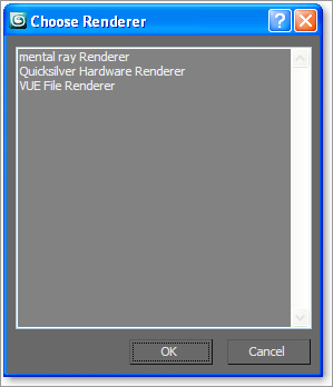
The Assign Renderer rollout (Figure 11-12) displays which renderers are assigned to your scene. Four types of renderers are available in 3ds Max by default (without any additional plug-ins installed) as shown in Figure 11-13:
Default Scanline Renderer The Scanline Renderer renders the scene as a series of horizontal lines.
mental ray Renderer This is a general-purpose renderer that can generate physically correct simulations of lighting and material effects.
VUE File Renderer The VUE File Renderer creates VUE (.vue) files, typically for natural environments.
Quicksilver Hardware Renderer Quicksilver is a renderer new to 3ds Max 2011 that engages the CPU and the graphics card’s processor (GPU) to quickly render your scene. This is useful for test renders and for quickly approximating how gaming engines may look.
Figure 11-12: Assign Renderer rollout

Figure 11-13: Choose Renderer dialog box
VUE and Quicksilver are not covered in this book because they are advanced renderers; however, mental ray rendering is covered later in this chapter.
Rendering the Bouncing Ball
Seeing is believing, but doing is understanding. In this exercise, you will render the Bouncing Ball animation from Chapter 8, “Introduction to Animation,” to get the feel for rendering an animation in 3ds Max. Just follow these steps:
1. Set your Project folder to the Bouncing Ball project that you downloaded to your hard drive from the companion web page at www.sybex.com/go/intro3dsmax2011. Open the Animation_Ball_02.max file in the Scenes folder. Let’s render a movie to see the animation.
2. Open the Render Setup dialog box. In the Time Output section, select Active Time Segment: 0 to 100.
3. In the Output Size section, select the 320 × 240 preset button and leave Image/Pixel Aspect as is.
4. Leave the Options group at the default, and skip down to the Render Output section. Click the Files button to open a Render Output File dialog box. Navigate to where you want to save the output file, preferably into the RenderOutput folder in your Bouncing Ball project. Name the file Bounce Ball, and click the drop-down menu next to Save as Type to choose MOV QuickTime File (*.mov) for your render file type. Normally, we would render to a sequence of images rather than a movie file like this; however, for short renders a QuickTime file works out fine.
By default, 3ds Max will render your file(s) to the RenderOutput folder in the current project directory.
Apple’s QuickTime movie file format gives you a multitude of options for compression and quality. The quality settings for the QuickTime file are not the same as the render quality settings.
5. After you select MOV QuickTime File and click the Save button, the Compression Settings dialog box, shown in Figure 11-14, opens. Set the parameters for the QuickTime file as indicated:
- Compression Type: Photo–JPEG
- Frames per second: 30
- Compressor Depth: Color
- Quality: High
Click OK.
Figure 11-14: QuickTime compression settings affect the quality of the rendered QuickTime video file.
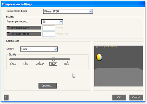
If you are concerned about the file size of your renders, you can slide the Quality bar to a lower quality setting for the compressor. The Photo-JPEG compressor makes fairly good images with small file sizes. However, you’ll want to deliver your renders at the highest quality you can muster. To improve quality, use a different compressor type. For example, Animation is lossless and makes big files, but those big files look much better.
6. Skip down to the bottom of the Render Setup dialog box, and verify that Production is selected. Select the viewport you want to render in the View drop-down menu. You need to render Camera01.
7. Click Render. The Rendered Frame Window will show you how the frames look as they render as the renderer goes through the sequence of frames, and the Rendering dialog box will appear.
After the render is complete, navigate to your render location (by default it is set to the RenderOutput folder for the Bouncing Ball project). Double-click the QuickTime file to see your movie, and enjoy a latte.
Renderer Tab Basics
The Renderer tab, found in the Render Setup dialog box, has options that determine the look and quality of the render. The options that are displayed in this tab depend on which renderer you assigned to render your scene. We will cover the Default Scanline Renderer in the following sections and mental ray a bit later in the chapter. This rollout sets the parameters for the Default Scanline Renderer.
Options
Figure 11-15: The Options section of the Renderer tab in the Render Setup dialog box

Most of the features in Options (Figure 11-15) are used to make rendering a scene more efficient. If you want to do a quick render of an animation, for example, turn off Mapping and Shadows. You will still see the movement, but the processing will go faster.
Antialiasing
Aliasing is the staircase effect you see in an image just at the edge of a line or area of color, particularly when that edge is at an angle, as shown in Figure 11-16.
Antialiasing can smooth this stepped effect on diagonal or curved lines. It blurs and mixes the color values of pixels adjacent to the jagged line or curve, as shown in Figure 11-17. Turning off this feature will speed up your renders, but the quality loss will be noticeable.
Turning off Antialiasing disables the Force Wireframe setting. Geometry renders according to the material assigned to it even if Force Wireframe is turned on. Turning off Antialiasing also disables Render Elements. If you need to render elements, be sure to leave Antialiasing on (Figure 11-18).
Figure 11-16: Aliasing is the stepped effect on diagonal and curved lines. Notice the top ridges of the fruit and its stem.
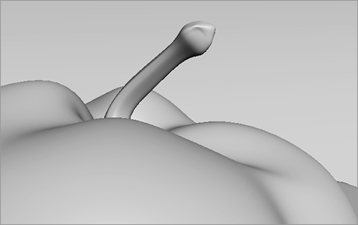
Figure 11-17: Antialiasing helps smooth jagged diagonal and curved lines.

Figure 11-18: The Antialiasing group of parameters

Filters
Filters are the last step in antialiasing. You can use them to access different methods of calculating the antialiasing at the subpixel level in order to sharpen or soften your final output. You don’t need to worry about which filter to use until you have much more rendering experience under your belt. The Area filter, which is the default filter, will work great (Figure 11-19).
Figure 11-19: Filter drop-down menu

If you are curious about the different filter types, select a filter. A short description of it will appear in the box below the Filter Maps check box.
With motion blur, a renderer can simulate how the eye or a camera sees an object in motion. When an object moves relatively fast, your eye (or a camera) perceives a blur on the object. Using motion blur for an animation can greatly enhance the fidelity of your render, although it adds more processing time. Use motion blur sparingly in most scenes. It takes a careful eye to choose the right blur amount for an object.
The Renderer tab in the Render Setup dialog box has two sections used for setting the type of motion blur you need.
Figure 11-20: Object Motion Blur section
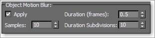
Object Motion Blur
The Object Motion Blur section (shown in Figure 11-20) lets you access the motion blur settings.
The Object Motion Blur settings are as follows:
Duration (Frames) The higher the Duration number, the more blur you get. You can see the difference in the motion blur for the ball in Figure 11-21.
Samples This setting determines how many duration subdivision copies are sampled. The higher the Samples number, the better the motion blur quality.
Duration Subdivisions This setting determines how many copies of each object are rendered within the duration. The higher the Subdivisions number, the smoother the motion blur will look.
Figure 11-21: Different durations give different motion blur lengths.

Setting the Duration very high and the Samples and Duration Subdivisions low will give you a ghosting effect that will kill the look of the motion blur. You will need to find the right balance to achieve a believable blur. Remember that less is more. Just a touch of motion blur may be all a scene needs.
Figure 11-22: Choose the type of motion blur for an object through its Object Properties dialog box.

Image Motion Blur
As you’ll notice in the Render Setup dialog box, Object Motion Blur is turned on by default. However, you still need to enable motion blur on a per-object basis; this means you have to toggle motion blur on for any object that you want to render with blur.
To turn on motion blur, select the object and right-click on it in a viewport. From the Quad menu, choose Object Properties. Select the type of motion blur (shown in Figure 11-22) you want, and then adjust the parameters in the Renderer tab.
The difference between Object and Image motion blur types can be seen in Figure 11-23. The bouncing ball on the left is rendered with Object motion blur, and the one on the right is rendered with Image motion blur. Both are rendered with the same Duration. The Image motion blur renders smoother, although it may not be as accurate because it is a smearing effect created after the object is rendered into the image. The Object blur renders the blur during the scanline rendering process itself.
For now, you only need to be concerned with the Duration parameter for an Image motion blur. This setting, as with the Object motion blur, sets the amount (and therefore the length) of the blur. Remember not to go overboard with motion blur. A little goes a long way.
Figure 11-23: Different motion blur types give you different results. The one on the left is Object motion blur, and the one on the right is Image motion blur.

ActiveShade is a fantastic 3ds Max feature that lets you interactively preview a render as you make changes in the scene. This is particularly helpful for texturing and lighting because the floating ActiveShade dialog box updates whenever you make a light or material change in the scene.
ActiveShade doesn’t render Atmospheric effects.
Figure 11-24: ActiveShade rendering toggle

To enable ActiveShade, open the Render Setup dialog box (![]() ). At the bottom of the dialog box, click to toggle on the ActiveShade rendering, as shown in Figure 11-24. Pick your viewport, and either click the ActiveShade button in the Render Setup dialog box or click the Render button in the Main toolbar. The icon in the Main toolbar changes (
). At the bottom of the dialog box, click to toggle on the ActiveShade rendering, as shown in Figure 11-24. Pick your viewport, and either click the ActiveShade button in the Render Setup dialog box or click the Render button in the Main toolbar. The icon in the Main toolbar changes (![]() ) as you switch from Production rendering to ActiveShade rendering.
) as you switch from Production rendering to ActiveShade rendering.
You can have only one ActiveShade dialog box open at a time. If you try to open another dialog box, an alert will ask whether you want to close the other dialog box.
Figure 11-25: Select ActiveShade from the context menu.

You can also turn a viewport into an ActiveShade dialog box. Select the viewport where you want to enable ActiveShade, click on the middle Point-of-View viewport label, and from the menu choose ActiveShade, as shown in Figure 11-25.
That viewport will then become an ActiveShade viewport and will update a render every time you make changes to the scene. This helps keep the clutter of open dialog boxes to a minimum. You should switch off ActiveShade and enable Production before continuing with the rest of the chapter.
Cameras in 3ds Max, as shown in the Perspective viewport in Figure 11-26, capture and output all the fun in your scene. In theory, the cameras in 3ds Max work as much like real cameras as possible. Hence, the more you know about photography, the easier these concepts are to understand.
The camera creates a perspective through which you can see and render your scene. You can have as many cameras in the scene as you want. However, it’s a good idea to position the camera you’re planning to render with where you want it for your final framing. You can use the Perspective viewport to move around your scene as you work, leaving the render camera alone.
Figure 11-26: A camera as seen in the Perspective viewport

Creating a Camera
There are two types of cameras in 3ds Max: Target and Free. A Target camera, much like a Target spotlight, has a Target node that allows it to look at a spot defined by where the target is placed (or animated). A Target camera is easier to aim than a Free camera because once you position the target object at the center of interest, the camera will always aim there.
Figure 11-27: Cameras in the Create panel

On the other hand, Free cameras have only one node, so they must be rotated to aim at the subject, much like a Free spotlight. If your scene requires the camera to follow an action, you will be better off with a Target camera.
You can create a camera by clicking on the Cameras icon (![]() ) in the Create panel and selecting either of the two camera types, as shown in Figure 11-27.
) in the Create panel and selecting either of the two camera types, as shown in Figure 11-27.
To create a Target camera, click in a viewport to lay down the Camera node, and then drag to pull out and place the Target node. To create a Free camera, click in a viewport to place it.
Using Cameras
Figure 11-28: Stock lenses make it easy to pick the right lens for a scene.

A camera’s main feature is the lens, which sets the focal length in millimeters and also sets the field of view (FOV), which determines how wide an area the camera sees, in degrees. By default, a 3ds Max camera lens is 43.456mm long with an FOV of 45 degrees. This default lens will most likely meet all your camera needs, but in case you need to change the lens, you can use the Lens or FOV parameters to create a new lens using the spinner or by entering a value. To change a lens, you can also pick from the stock lenses available for a camera in its Modify panel parameters, as shown in Figure 11-28.
The 3ds Max Lens and FOV parameters are tied together. One drives the other because the focal length of a real lens sets the field of view.
The most interactive way to adjust a camera is to use the viewport navigation tools. You can then place the camera while you see its field of view in that viewport. The Camera viewport must be selected for the viewport camera tools to be available to you in the lower-right corner of the UI. You can move the camera or change the lens or FOV. Chapter 3, “The 3ds Max Interface,” has a complete list of the tools in the “Viewport Navigation Controls” subsection. You can also change a camera by selecting the camera object and moving and rotating it just as you would any other object.
Talk Is Cheap!
The best way to explain how to use a camera is to create one, as in the following steps:
1. Set your project to the Rendering Scene Files project you have downloaded to your hard drive from this book’s companion web page. Open the Camera Create.max scene file in the Rendering Scene Files folder downloaded from the web page. This is the chessboard from the lighting chapter, but without a camera. Creating a camera is the same as creating a light. It’s easier to create a camera in the Top viewport, so you can easily orient it in reference to your scene objects. Figure 11-29 shows the intended position of a camera for this scene.
2. In the Create panel, click the Cameras icon (![]() ). Select the Target camera and go to the Top viewport. Click from the bottom of the viewport and drag to the chessboard. The first click creates the Camera object. The mouse drag and release sets the location of the target, just like creating a target light. You may need to zoom out your view to accommodate placing the camera.
). Select the Target camera and go to the Top viewport. Click from the bottom of the viewport and drag to the chessboard. The first click creates the Camera object. The mouse drag and release sets the location of the target, just like creating a target light. You may need to zoom out your view to accommodate placing the camera.
3. The camera was created along the ground plane. You need to move the entire camera up using the Front viewport. The easiest way to do this is to select the camera and target using the line that connects the camera and target. That will select both the target and camera so you can move them as a unit. Use the Move tool to relocate the camera higher in the scene to place it at the level of the chess pieces.
Figure 11-29: The camera would go here.

4. To see the Camera viewport, select a viewport and press the C key. This changes the viewport to whatever camera is currently selected. If there are multiple cameras in your scene and none are selected, when you press C you will get a dialog box that gives a list of the cameras from which you can choose.
5. Now Render the scene (press F9 or click the teapot icon) through the camera you just created and positioned. Find a good framing for the chessboard and set your camera.
When the camera is set up, take some time to move it around and see the changes in the viewport. Moving a camera from side to side is known as a truck. Moving a camera in and out is called a dolly. Rotating a camera is called a roll. Also change the Lens and FOV settings to see the results.
Zooming a lens (changing the Lens parameter) is not the same as a dolly in or dolly out. The field of view changes when you zoom, and it stays constant when you dolly. They will yield different framings.
Animating a Camera
Now that the camera is in the scene, let’s add some animation to the camera. Camera animation is done in the same way as animating any object. You can animate the camera or the target or both. You can also animate camera parameters such as Lens or FOV.
1. In the scene you just worked in, select the camera.
2. Move the Time Slider to frame 30.
3. Press the N key to activate Auto Key, or click its icon.
4. Use the Move tool to move the camera farther away from the still life. The idea is to create a dolly out of the still life.
5. Scrub through the animation and make any edit you desire.
If you are comfortable using the Perspective viewport, you can convert it to a Camera view by pressing Ctrl+C. Cool trick!
Clipping Planes
You can limit what your camera sees in a scene. For example, in a huge scene, you can exclude or clip the geometry that is beyond a certain distance by using clipping planes. This helps minimize the amount of geometry that needs to be calculated. Each camera has a clipping plane for distance (Far Range) and foreground (Near Range), as shown in Figure 11-30 and Figure 11-31, respectively. The near clipping plane will clip geometry within the distance designated from the camera lens.
You can also use clipping planes to create a cutaway look for a model. Set your near clipping plane to a specific distance into the object, and the object will render as if it were sliced, giving you a perfect cutaway look.
Figure 11-30: A far clipping plane cuts off the distant extents of a scene.
Figure 11-31: A near clipping plane cuts off the extents directly in front of a camera.

Likewise, if you find that a model or scene you have imported looks odd or is cut off, check to make sure your clipping planes are adjusted to fit the extent of the scene, especially with imported models.
Figure 11-32: Check the Clip Manually check box and set the distances.

To enable clipping planes, click the Clip Manually check box and set the distances needed, as shown in Figure 11-32.
Once you turn on manual clipping planes, the camera will display the near and far extents in the viewports with a red plane marker, as shown in grayscale in Figure 11-33.
Figure 11-33: When Clip Manually is enabled, a camera will display its manual clipping planes in a viewport.
Figure 11-34: Safe Frame gives you a suggested boundary for the action of your framing.

Because every TV is different, what you see on one screen may look somewhat different on a different screen. To help make sure the action of your scene is contained within a safe area on all TV screens, you can enable the Safe Frame view in any viewport. This will, as shown in Figure 11-34, show you a set of three boundaries in your viewport.
The Live area is the extent of what will be rendered. The Action Safe area is the boundary where you should be assured that the action in the scene will display on most if not all TV screens. Most TVs will display somewhere between the Action Safe and the Live areas. Finally, the Title Safe boundary is where you can feel comfortable rendering text in your frame. Because some TVs distort the image slightly at the edges, any text that falls outside the Title Safe area may not be readable. Although they are based on TV technology from years ago, these conventions hold true in professional production to this day. The Safe Frame areas are still good guidelines to use when framing your shot.
To view the Safe Frame areas in the chosen viewport, click on the viewport’s name in the upper left hand corner of the viewport to access the context menu, and then choose Safe Frame from the list.
Figure 11-35: The Render Elements tab in the Render Setup dialog box

The Render Elements tab is another tab in the Rendering Scene dialog box, and is shown in Figure 11-35. You might not need this feature as a beginner, but you will be surprised at the control you get when you render your scene into separate passes to composite later. As a beginner, you should concentrate on becoming familiar with rendering and lighting. As the months pass and you feel more comfortable rendering, you should discover that most CG is layered.
This means that separate passes are rendered and then layered or composited together with finer control in a program such as Photoshop for still images, and Composite, After Effects, or Nuke for image sequences. The ability to layer is another reason why rendering to image files is preferred over rendering to movie files.
However, you will need to understand compositing to be able to control and layer the elements back together.
Shadows and reflections are the main elements that you might consider rendering separately, especially when you are first learning. When these elements are separate, you gain a greater degree of control in compositing because you can affect the shadows or reflections any way you want (soften, color, transparency, etc.) as you composite them back on top of the image. For example, if you render a scene of a tree casting a shadow across a lawn, you will have to render the entire scene again if you decide to lighten the shadow color. If you have the shadow as a separate pass, you can very easily and interactively change the darkness of the shadow as you composite it in Shake, for instance.
The following list describes common elements to render:
Alpha Renders a black-and-white matte to be used in compositing. This is especially helpful when you need different mattes for different objects in your scene. In Figure 11-36, the chessboard is shown rendered in Alpha only.
Figure 11-36: The Alpha element

Reflection Renders only the reflections so you can composite them separately onto the color render to have control over the amount of reflection in the final composited image, for example. Figure 11-37 shows the chess pieces’ reflections in the chessboard rendered as an element.
Refraction Renders only refracting elements in transparent or translucent objects, so they may be layered in the composite at a later time.
Self-Illumination Renders the incandescence of an object’s material separately, so its intensity may be controlled in composite.
Shadow Renders only the shadows cast in the scene into the alpha channel of the image. Figure 11-38 shows the chess pieces’ Shadow element. Keep in mind that you will have to render to an image format that has an alpha channel, such as TIFF.
Figure 11-37: The Reflection element
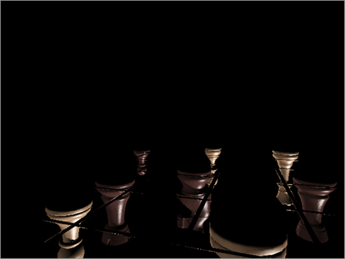
Figure 11-38: The Shadow element as shown in the alpha channel of the image

Figure 11-39: The Specular element

Figure 11-40: The Z-Depth element
Specular Renders only the highlights on an object’s glossy material. Figure 11-39 shows the specular highlights on the chess pieces. Look at how the nicks and scratches on the pieces are so noticeable in this element.
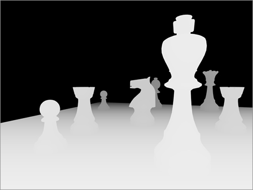
Z-Depth Renders a grayscale image that responds to the depth of a scene. The closer an object or a part of an object is, the whiter it renders. The farther from the camera an object or its parts are, the darker the render. This pass is then used in a compositing program, such as Combustion, to create a sense of haze or blur to add a depth of field to the image. Figure 11-40 shows a Z-Depth pass generated for the chessboard scene.
Now, let’s try rendering something. Follow along with these steps.
1. Select the Render Elements tab in the Render Setup dialog box, click the Add button, and select the element you want to render.
2. Once you select a render element, it will be added to the element list. Then you’ll need to go down to the Selected Element parameters to input where you will save the bitmap elements when you click the “…” button (![]() ), as shown in Figure 11-41. The dialog box will name the element automatically. However, when you go into the Render Element Output File dialog box to save it, you should name it again.
), as shown in Figure 11-41. The dialog box will name the element automatically. However, when you go into the Render Element Output File dialog box to save it, you should name it again.
3. If you want each element to be rendered in its own Rendered Frame Window, check the Display Elements box. If it is unchecked, the program will render the elements to a file and the Rendered Frame Window will not show you the progress of each element.
4. Click the Render button to begin a render. 3ds Max will render the entire scene, and then output the elements as needed.
Figure 11-41: In the Render Element Output File dialog, enter where you want to save the bitmap elements.

Rendering Effects offers a variety of special effects such as lens effects, film grain, and blur to add to your render. Rendering Effects allows you to create effects without having to render to see the results. They are rendered after your scene is rendered, and they are added to the rendered image automatically.
Lens Effect: Glow
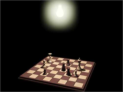
You will add a glow effect to a light bulb hanging over the chessboard in a scene.
For this scene, we’ve chosen to glow the Light Bulb object. You can also glow a light; this property can be set only through Object Properties.
Figure 11-42: Select Object Properties from the Quad menu.

You will glow the Light Bulb object in the following steps:
1. Set your project to the Rendering Scene Files project you downloaded from the web page. Load the Chess_Glow.max scene file from the Rendering Scene Files project’s Scenes folder.
2. Select the light bulb, and then right-click. From the Quad menu, select Object Properties, as shown in Figure 11-42.
3. In the Object Properties dialog box, go to the G-Buffer section and assign 2 as the Object ID number for the glow effect, as shown in Figure 11-43. This tells 3ds Max which object gets the glow. The number you assign doesn’t matter unless you want different glows on different objects. In that case, each glow object would receive its own Object ID number.
Another way you can assign glow is through the object’s material. Go to the Material Editor, and in the toolbar click and hold on the Material ID Channel button. In the Slate Material Editor, you simply right-click on the material node and select Material ID Channel to access the different ID numbers to assign. The benefit of using the material for the glow is that you can glow any object that has the material applied.
4. In the menu bar, choose Rendering ⇒ Effects to open the Environment and Effects dialog box. Click the Add button. Then pick Lens Effects from the Add Effect dialog box. Figure 11-44 shows that the Lens Effects has been added.
5. Scroll down to Lens Effects Parameters, select Glow, and press the arrow button (or double-click Glow itself) to add Glow to the box on the right, as shown in Figure 11-45.
Figure 11-43: Set a unique number for the Object ID.
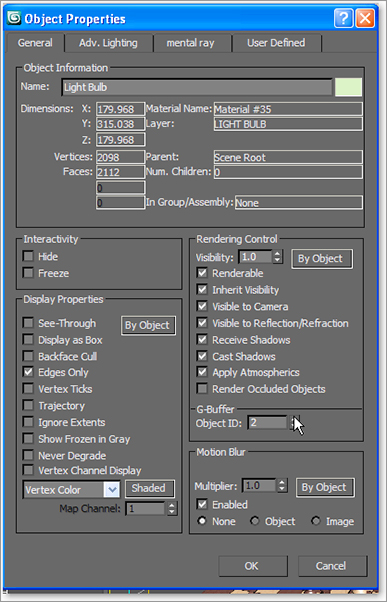
Figure 11-44: Adding Lens Effects to the Environment and Effects dialog box

Figure 11-45: Adding Glow in the Lens Effects Parameters

6. While still in the Environment and Effects dialog box, scroll down to the Glow Element rollout. This is where you create the settings for the glow effect. There are two tabs:
Figure 11-46: Set the size and color of the glow.

Parameters This tab is where you set the size and color of the glow, as shown in Figure 11-46.
Options This tab is where you can assign the glow to the object desired. Under Image Sources, you have to choose how the glow will be applied to the object, through the material or object properties.
7. Click the Options tab. Because you are creating the light bulb’s glow through the Light Bulb object’s Object ID, click to enable Object ID and set the Object ID parameter to 2, as shown in Figure 11-47. Leave the other parameters at their default values.
Figure 11-47: Set the Object ID parameter to 2.

8. Click over to the Parameters tab to set the glow’s size. Setting the size for the glow can be a bit tricky because the size of the glow depends on the size of your object. Set the Size value to 5. Leave Intensity set at the default; once you render the effect, you can adjust the Intensity setting.
Figure 11-48: Glow!
9. To add color to the glow, you can use two methods: You can set the Use Source Color parameter to set the glow color to a percentage of the object’s material color. You also can use the Radial Color parameters to set the colors for the inside of the glow (on the left in the Radial Color parameter) and the outside of the glow (on the right in the Radial Color parameter). In this case, set Use Source Color to 65 because the light bulb has a yellow material applied. If you have Interactive Preview enabled (see the note in this section), you can see how the glow looks. Otherwise, run a render to check the look.
10. The default intensity looks okay, but it could be brighter. Change the Intensity to 165. Render. Okay, it looks good. See Figure 11-48.
Using Preview
Figure 11-49: The effects preview

Using the preview in the Environment and Effects dialog box as shown in Figure 11-49 (in the Effects tab), provides a much easier way to view the effects than rendering a frame does. You can select whether you want to preview all of the effects (All) in the scene or just the one you are working on (Current). Toggling Interactive updates the preview when you change the Effects parameters by opening a Render dialog box and updating it as you make changes. Enabling Interactive may cause your computer to slow down, so leave it unchecked and use the Update Effect button when you want to see an update.
Raytraced Reflections and Refractions
In this section, you will learn how to create realistic reflections and refractions in your renders. As you saw in Chapter 7, “Materials and Mapping,” you can apply an image map to an object’s material’s Reflection parameter to add a fake reflection to the object. To get a true reflection of the other objects in the scene, you will need to use raytracing methodology. There are essentially two ways to create raytraced reflections in a scene: by using a Raytrace map or by using a Raytrace material.
The Raytrace material is a more detailed solution; however, it can take twice as much time as using a Raytrace map, because the Raytrace material requires more calculation.
As you learned in Chapter 4, “Modeling in 3ds Max: Part I,” determining the level of detail you need for a reflective surface is important. There is no reason to use the Raytrace material for a reflection unless your camera is right up on the object. In many cases, the Raytrace map looks great and saves tons of rendering time. Keep in mind though, the amount of control you will have with a Raytrace map is significantly less than with the Raytrace material.
First you will try using the Raytrace material.
Raytrace Material
In the following steps, you will learn how to use the Raytrace material to create reflections in a scene with a fruit still life arrangement.
Creating the Raytrace Material
1. Set your project to the Rendering Scene Files project you downloaded from the web page. Open the Still_Life_raytrace.max file found in the Scenes folder of the Rendering Scene Files project on the web page. Change the Camera view to Camera01 in one of the viewports if it isn’t already.
2. Open the Compact Material Editor and select a sample slot. Click the Get Material button (![]() ) and select the Raytrace material from the Material/Map Browser, as shown in Figure 11-50.
) and select the Raytrace material from the Material/Map Browser, as shown in Figure 11-50.
Figure 11-50: Select the Raytrace material.

Figure 11-51: The Raytrace Basic Parameters rollout

3. The parameters to create reflections are available through the Raytrace Basic Parameters rollout, as shown in Figure 11-51. Leave most of these parameters at their default values, but change the Reflect color swatch to white from black. This will set the reflection of the material all the way to the maximum reflectivity.
4. Change the Diffuse color swatch to black to turn the column that the fruit is sitting on black. This will make the column appear as a reflective black glass material in the render.
5. Apply the Raytrace material to the column in the scene. Render the Camera viewport. Figure 11-52 shows the result.
Figure 11-52: The Raytrace material renders reflections.

Tweaking the Render
Figure 11-53: The SuperSampling rollout

The render will show the Raytrace material on the column reflecting like a flat mirror. It looks very convincing, but you may notice the jagged edges or artifacts around the reflected objects. What you’re seeing is aliasing in the reflections. The antialiasing filters set by default may not be enough. Clone this rendered image by pressing the Clone Rendered Frame Window icon (![]() ), which is found in the Rendered Frame Window toolbar, to make a copy of this rendered image in another window.
), which is found in the Rendered Frame Window toolbar, to make a copy of this rendered image in another window.
Figure 11-54: Reflections with the Raytrace material with Local SuperSampling enabled

When the defaults aren’t enough, it is time for the heavy artillery: SuperSampling. SuperSampling is an extra pass of antialiasing. By default, 3ds Max applies a single SuperSample pass over all the materials in the scene. However, if a specific material needs more antialiasing, you can apply a separate SuperSample method to that material.
In the current still life scene, select the material slot for the column’s Raytrace material. Go to the SuperSampling rollout and uncheck Use Global Settings. Check Enable Local Supersampler. In the pull-down menu, choose Adaptive Halton, as shown in Figure 11-53.
The Adaptive Halton method performs well in this case. However, always try the regular patterns first; they tend to render faster. Render the scene, and you will notice a marked improvement in the quality of the reflections (Figure 11-54).
Raytrace Mapping
You can apply raytracing only to a specific map; you can’t apply it to the entire material. Because raytracing typically takes longer to render, this can save time. In this case, you will assign a Raytrace map to the Reflection map channel of a material to get true reflections in the scene, at a faster render time than using the material as you just did. Follow these steps:
1. In the scene you just worked in, open the Material Editor and select an unassigned sample slot. Keep the material set to Standard.
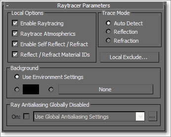
2. In the Maps rollout, click the mapping bar labeled None next to Reflection. Choose the Raytrace map in the Material/Map Browser, as shown in Figure 11-55.
Leave the Raytrace map parameters at the default, as shown in Figure 11-56.
3. In the Material Editor’s tool bar, click the Go to Parent button (![]() ) .
) .
Figure 11-55: Choose the Raytrace map.

Figure 11-56: The Raytrace map parameters
4. In the Blinn Basic Parameters rollout, change the diffuse color to black to match the black column from the previous render.
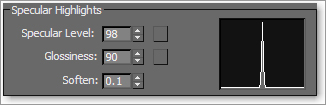
5. In the Specular Highlights section, change the Specular Level to 98 and Glossiness to 90, as shown in Figure 11-57.
Figure 11-57: The Specular Highlights parameters
6. Apply the material to the column object in the scene and Render the Camera viewport.
7. You will notice the same aliasing in the reflections as in the previous example. Set the SuperSampling as you did with the prior example, and render again.
Take a look at both the images created with reflections using the Raytrace material, and those created using the Standard material with the Raytrace map applied to Reflection. They look almost the same. This is good to know because it takes about half the time to render the Raytrace map. However, you will notice slightly better detail in the reflections created with the Raytrace material. You and the requirements of your scene will determine which reflection method works best in a particular situation. However, it’s good always to start with the Raytrace map to see if it creates enough detail without too much bother.
Refractions Using the Raytrace Material
Creating raytraced refractions in glass can be accomplished using the same two workflows as raytraced for reflections. The same conditions apply here. The Raytrace material renders more nicely, but it takes longer than using a Raytrace map for the Refraction map in a material.
Keep in mind that render times are much slower with refractions, especially if you add SuperSampling to the mix—so don’t freak out. Now you will create refractions using the Raytrace material:
1. In the same scene, change the Camera01 viewport to Camera02. This gives you a better view of the wine glass through which we will refract, as shown in Figure 11-58.
2. In the Compact Material Editor, select an unassigned sample slot and click the Get Material button. This material will be for the wine glass.
3. Choose the Raytrace material from the Material/Map Browser.
4. Go to the Raytrace Basic Parameters rollout, and change the color swatch for Transparency from black to white. (Black is opaque and white is fully transparent.)
5. Uncheck the box next to Reflect and change that spinner to 20. This sets a slight reflection for the material.
Figure 11-58: Changing Camera01 to Camera02
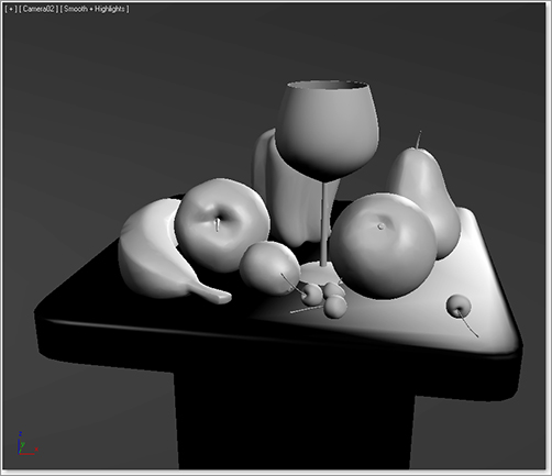
Figure 11-59: The Extended Parameters rollout for the Raytrace material

6. Take a look at the Index of Refr parameter. This value sets the Index of Refraction (IOR) value that determines how much the material should refract its background. For more on IOR, see the “Refractions” sidebar in this chapter. The value is already set to 1.55. Leave it at that value.
7. Go to the Extended Parameters rollout (Figure 11-59). The Reflections section of the parameters is at the bottom. Select Additive and change Gain to 0.7. This gives a bit of reflection brightness for the clear wine glass.
Figure 11-60: The Specular Highlights group parameters

8. Go to the SuperSampling rollout and uncheck Use Global Setting. Check Enable Local SuperSampler and keep it set to Max 2.5 Star.
9. In the Specular Highlights group, change the Specular Level to 98 and Glossiness to 90, as shown in Figure 11-60.
10. Apply the material to the wine glass. The glass will turn transparent in the viewport. Render. Figure 11-61 shows the result.
You will notice a very nice wine glass render, with the bell pepper refracting through it slightly. Change the Index of Refr parameter on the material to 8.0, and you will see a much greater refraction, as shown in Figure 11-62. That may work better for a nice heavy bottle, but it is too much for the glass. An Index of Refr parameter between 1.5 and 2.5 works pretty well for the wine glass, particularly at the bottom of the glass where it rounds down to meet the stem.
Figure 11-61: The wine glass refraction is rendered with the Raytrace material.

Figure 11-62: A much more pronounced refraction is rendered with an IOR of 8.0.

Refractions Using Raytrace Mapping
Just as you did with the reflections, you will now use a Raytrace map on the Refraction parameter for the wine glass material. In the following steps, you will create another refraction render for the wine glass:
1. While still in the same scene, open the Compact Material Editor and select an unassigned sample slot. You are going to keep the material set to Standard.
2. Go to the Maps rollout and click the bar labeled None, which is next to Refraction. Choose the Raytrace map from the Material/Map Browser. The material in the sample slot will turn transparent.
3. Click the Go to Parent button to return to the material’s parameters.
4. Go to the Maps rollout and click the bar labeled None next to Reflection. Choose the Raytrace map from the Material/Map Browser. Be warned that this setting will take a long time to render the image. If you have a slower computer or perhaps are in a rush, uncheck the Reflection Map box in the material’s parameters to turn off the reflection entirely.
5. Click the Go to Parent button to return to the material’s parameters.
6. Go to the Maps rollout and change the Reflection amount to 6. This will reduce the amount of reflection.
7. Go to the Blinn Basic Parameters rollout and change the Opacity value to 0.
8. Go to the SuperSampling rollout and uncheck Use Global Settings. Check Enable Local SuperSampler and keep it as Max 2.5 Star.
9. In the Specular Highlights group, change Specular Level to 98 and Glossiness to 90.
10. Apply the material to the Wine Glass object in the scene and render (Figure 11-63).Save the scene if you wish to keep it.
Figure 11-63: Use Raytrace map on the Refraction parameter to create a refraction in the wine glass.

You can control the IOR through the material’s parameters in the Extended Parameters rollout, in the Advanced Transparency section, shown in Figure 11-64. Set the IOR to different numbers to see how the render compares to the Raytrace material renders.
Figure 11-64: The Advanced Transparency section in the Extended Parameters rollout

The render will take quite some time to finish. The raytracing reflections and refractions slow down the render quite a bit. You can leave out the reflections if you’d like, but that will reduce the believability of the wine glass. You can also map a reflection as you did with the pool ball in Chapter 7; however, having true reflections will make the wine glass look much more realistic. When you raytrace both the reflection and the refraction, using the Raytrace material seems to be the better way to go.
Refractions
Refraction is the bending of light that creates a distortion of an image seen through a transparent or translucent object, such as glass. How light passes through from one medium, such as air, and into another medium, such as glass, determines how much light is bent and therefore how much refraction is seen. This phenomenon is simulated in a material using the Index of Refraction parameter (IOR). When there is no refraction, the IOR is set to 1; that is, there is no difference in the medium into and out of which the light is traveling. With an IOR higher than 1, the background distorts inside the object, such as when viewing a table through a crystal ball. With an IOR lower than 1, the refraction occurs at the edge of the transparent object, such as an air bubble in water.
The typical IOR value for glass is about 1.5. Because IOR relates to an object’s density, you may need to adjust the IOR to get the best possible result for different types of glass, for instance. The denser the object, the higher the IOR needs to be set. Of course, refractions require that an object be semitransparent so that you can see through it to the object(s) behind it that are being refracted.
Bringing It All Together: Rendering the Rocket
Now that you have some experience with the rendering workflow in 3ds Max, let’s take a quick look at rendering a short 45-frame sequence of the rocket. You will essentially take the rocket scene laid out in the previous chapter (with the atmospheric fog light through the window we set up). You’ll need to tweak a few of the scene settings, such as setting the rocket’s and environment’s materials to have raytraced reflections for maximum impact. You’ll also animate a camera move so you can render out a sequence you can pin to your refrigerator door. Let’s go!
Creating the Camera Move
We’ll begin by animating the camera.
1. Set your project to the Red Rocket project from the web page. Start by opening ROCKET_RAYTRACE_START.max.
This file is the same one we used at the end of Chapter 10, “3ds Max Lighting,” but all the Reflection maps have been taken out because we will be raytracing almost everything (Figure 11-65).
Figure 11-65: The rocket in its room, ready to go

2. To begin animating, click the Auto Key button while at frame 0 (![]() ) to activate it. Go to the timeline at the bottom of the interface and move the Time Slider to 45. Now when changes are made, key frames will be created for any selected objects.
) to activate it. Go to the timeline at the bottom of the interface and move the Time Slider to 45. Now when changes are made, key frames will be created for any selected objects.
3. Select the Camera viewport because we are going to create a simple camera animation. As you saw in Chapter 3, when the Camera viewport is selected, the viewport navigation tools change, as shown in Figure 11-66. These Navigation tools make animating the camera easier.
Figure 11-66: Camera viewport navigation tools

4. Select the Dolly Camera tool (![]() ) to move the camera closer to the rocket. Click and drag the Dolly Camera tool in the Camera viewport until you see only the front of the rocket, as shown in Figure 11-67.
) to move the camera closer to the rocket. Click and drag the Dolly Camera tool in the Camera viewport until you see only the front of the rocket, as shown in Figure 11-67.
5. Select the Truck Camera tool (![]() —this icon may be hidden in the flyout under a pair of footstep icons), which allows you to pan the camera. Click and drag up and to the left in the Camera viewport to center the rocket in the viewport to match the framing you see in Figure 11-68.
—this icon may be hidden in the flyout under a pair of footstep icons), which allows you to pan the camera. Click and drag up and to the left in the Camera viewport to center the rocket in the viewport to match the framing you see in Figure 11-68.
6. Back to the Camera Navigation tools, select the Orbit Camera tool (![]() ). Center the tool in the middle of the viewport, and click and drag to the left until you get a better view of the side of the rocket, as shown in Figure 11-69.
). Center the tool in the middle of the viewport, and click and drag to the left until you get a better view of the side of the rocket, as shown in Figure 11-69.
Figure 11-67: Dolly the camera closer to the rocket.

Figure 11-68: Truck the camera to match this framing.

Figure 11-69: Orbit to the side of the rocket.

Figure 11-70: The final framing for your rocket at frame 45

7. Use the Truck Camera tool again to move the camera more to the left and to center the rocket in the viewport. Figure 11-70 should be the final position of the rocket in the camera view. Your camera move will end at this position at frame 45 of the animation.
8. Go to the animation controls shown in Figure 11-71, and play the animation you created. Make any adjustments you would like to personalize the camera move. Turn off the Auto Key button and save your file. Remember to version up your file so you don’t overwrite your current work.
Figure 11-71: Use the animation controls to play the animation.

Adding Raytraced Reflections
In Chapter 7, we used reflection bitmaps to fake the reflections on the rocket by using a bitmap to create the illusion of reflection. This technique usually looks very good, but there are circumstances where you need the reflections to look more accurate within the scene. This is when you use Raytrace map instead of a bitmap image. The Raytrace map calculates reflections as they work in the real world, reflecting the object’s environment. Of course, in order for raytraced reflections to work, your object needs to be in an environment, much like the rocket’s simple room. There has to be something around the object to reflect. To demonstrate this, we are going to add Raytrace to the rocket and the room.
The Rocket
To add raytraced reflections to the rocket, begin here:
1. Open the Compact Material Editor, and you will see all the materials that were created earlier for the rocket.
2. In the Compact Material Editor, select the first sample sphere at the top left; this is the texture for the left side of the rocket body.
This is the only side of the rocket that will be visible in our renders, so that is the only side we will change.
3. Go to the Maps rollout, and you will see that the bitmap reflection from Chapter 7 has already been removed. If you are continuing with your own scene file, simply remove the current bitmap before continuing. To do so, just drag None from another map slot onto the Reflection channel.
4. Change the Amount value for Reflection to 20, and click None to add a map. In the Material/Map Browser, choose Raytrace.
5. Render a frame, and you should see some reflections of the room. If you want the rocket to have a higher amount of reflection, you only have to go back to the Maps rollout and make the Reflection value higher than 20.
6. Go through the materials in the Material Editor for the rocket’s remaining parts to add Raytrace to their reflections as well. For those materials in the ROCKET_RAYTRACE_START.max scene, you will notice that the reflection bitmaps have already been removed from the following parts of the body to make them ready for the Raytrace map:
- Both sides of the rocket’s body (although you only see one side of the body in these renders, you may opt to put Raytrace on both.)
- The nose
- The fins
- The hubcaps (white part of the wheels)
- The tires (black part of the wheels)
- The seat
Figure 11-72: The rocket with raytraced reflections

7. Go through the Material Editor and add Raytrace to those materials. If you are continuing with your own scene, replace the reflection bitmap on the list of materials with the Raytrace map.
We aren’t adding Raytrace to everything on the rocket, because Raytrace reflections take a lot more time to render. Don’t bother adding them to parts of the scene that won’t make a difference. Figure 11-72 shows a render of the rocket with the Raytrace map applied to the aforementioned materials.
The Room
In the room, the floors and the glass on the window should also have raytraced reflections, since reflections would look very good raytraced on these objects, especially with the camera move. Let’s start with the hardwood floor.
The floors have one issue with which we have to deal. The grooves between the wood panels should not have reflections; only the panels should reflect. We need to apply a mask to the reflections to block the Raytrace from the grooves in the floor. The floor already has a bump map to mark out the grooves, so that is what we will use as the mask as well.
If the textures we are talking about do not display in the viewports, simply select the material in the Material Editor and click on the Show Standard Map in Viewport icon in the Material Editor. If the bitmap files’ paths are not connected when you open the scene file, 3ds Max will open an error dialog box, allowing you to browse for the missing image(s). This can occur when sharing projects and scenes between computers, as is a common occurrence. In this case, simply navigate to that project’s SceneAssets/Images folder to find the disconnected bitmap image(s).
Figure 11-73: Mask map parameters for the floor’s reflections.

1. Go to the Compact Material Editor and select the sample Sphere material for the floor (the material is called FLOORS).
2. Go to the Maps rollout (Figure 11-73), change the Reflection Amount to 50, and click on None to add a map. Instead of selecting Raytrace, select Mask.
3. Click on the None button next to Map, and select Bitmap from the Material/Map Browser. Navigate to the SceneAssetsImages folder of the Red Rocket project and choose WoodFloorREF.tif.
Figure 11-74: Change the bitmap back to Texture instead of Environ.

4. When the bitmap is applied, you will be in the Bitmap Parameters rollout. Go to the Coordinates rollout and change from Environ to Texture. Whenever you apply a bitmap to reflections by default, 3ds Max changes the bitmap to Environ because it is trying to behave like a real reflection. We need the mask bitmap to behave like a normal bitmap and look to the UVW Map modifier applied to the floor for its coordinates (Figure 11-74).
5. Now click the Go to Parent button in the Material Editor toolbar to get back to the Mask Parameters rollout. Select the None bar next to Mask and then click Raytrace from the Material/Map Browser.
6. Render the frame, and you’ll notice the reflections are pretty high. But you can also see how the grooves have no reflection, so the mask works! For a better reflection, turn the Reflection Amount setting in the Maps rollout down to 10 for the floor. Click the Go to Parent button then open the Maps rollout. Figure 11-75 shows a render of the rocket.
Figure 11-75: The reflections on the floor look great!

Turning On the Environment Effects
Figure 11-76: The Raytracer Global Parameters rollout

Any Raytrace maps added to your scene can make the render time very long. If you are just trying to check an animation, it is wise to deactivate Raytrace while you do your test renders. To do so, open the Render Setup dialog box (press F10 or click on its icon in the Main toolbar) and click on the Raytracer tab, then go to the Global Raytracer Engine Options group, as shown in Figure 11-76. Just remember to turn it back on when your test renders are finished.
Figure 11-77: Re-check Atmospherics in the Render Setup dialog box ⇒ Common tab ⇒ Options section.

To round out the scene, we need atmosphere: Volume light was already added to the key light in the previous chapter, so we just need to turn it on. The Render Setup dialog box has a Deactivate button for atmospherics, so you can easily turn them on and off as you test render. To re-enable atmospherics in the render, go to the Common tab of the Render Setup dialog box and, under the Options section, check the Atmospherics box as shown in Figure 11-77.
Render the frame (Figure 11-78).
Figure 11-78: The rocket is rendered with the volume light shining through the window.

Outputting the Render
This scene has an animated camera, so doing a simple render just won’t do. We need to render out the entire 45 frames of the camera move. As you saw with the Bouncing Ball render earlier in the chapter, rendering out a sequence of images is done through the Common tab of the Render Setup dialog box.
Figure 11-79: Output Size sets the resolution of the render.

In the Time Output section, click to select Active Time Segment: 0 to 45, as shown in Figure 11-79. The scene file you started with from the Red Rocket project will have its time segment set properly to 1 to 45. If you are working from your own scene file, however, you can either set the Active Time Segment in your scene to 1 to 45, or you can set the Range in the Render Setup dialog box manually to render from frame 1 to frame 45.
The resolution of the render is set in Output Size. The default resolution is 640 × 480.
Figure 11-80: The Output Size section has preset buttons to choose the resolution, or you can input the size in the Width and Height type ins.

On a good computer, this render takes about 1 minute 20 seconds per frame with environments turned on; that means the whole 45-frame sequence will take just over one hour to render. If you want to render faster and you don’t mind the render being smaller, you can render out at a smaller resolution. Half the default size is 320 × 240 and will cost you one-fourth of the higher resolution’s time (15 to 20 minutes or so) to render.
To change to the lower resolution, in the Output Size section, click on the preset button 320 × 240, as shown in Figure 11-80. Now it should take just about 20 seconds per frame to render.
Go to the Render Output section of the Render Setup dialog box and click Files to open the Render Output File dialog box shown in Figure 11-81. Typically, animations are rendered out in a sequence of images, but for simplicity’s sake, we will render out to a QuickTime movie as we did with the bouncing ball earlier in this chapter.
Figure 11-81: Name your output render movie file.

In the Render Output File dialog box (Figure 11-81), select where you want to store the rendered file, and pick a name for the QuickTime movie (Rocket_Raytrace.mov, for example). Then, in the Save as Type drop-down menu, choose MOV QuickTime File (.mov) and click Save. The Compression Settings dialog box will appear, as shown in Figure 11-82. Again, it is generally preferable to render to a sequence of images rather than a movie file; however, in this case a QuickTime movie file will be best.
Figure 11-82: The Compression Settings dialog box

In the Compression Settings dialog box, select Photo–JPEG for the compression type, set Frames per Second to 30, and set Quality to Best, just as you did with the Bouncing Ball exercise. You can set the Quality slider to a lower value for a smaller QuickTime file. But remember, this Quality setting applies only to the compression of the QuickTime file and not to the render itself. Click OK to return to the Render Output File dialog box, and click Save to return to the Render Setup dialog box.
Save your scene file, and you are ready to render! Just click Render in the Render Setup dialog box, and go outside to play catch with your kids or hassle your spouse or sibling into a needless argument for a little while. In about 20 minutes (or one hour if you chose to render at 640 × 480), run back inside and play the QuickTime file saved in the location you chose earlier. Then take a huge magnet and stick your monitor to your fridge door. Voilà! You are now ready to enter the world of rendering with mental ray.
mental ray is a popular general purpose renderer that has fantastic capabilities. One of mental ray’s strengths is its ability to generate physically accurate lighting simulations based on indirect lighting principles. Indirect lighting is when light bounces from one object in a scene onto another object and casts light on it. In addition, incandescence or self-illumination from one object can light other objects in the scene. A direct light such as from an Omni light is not necessarily required.
mental ray’s reflections and refractions take on very real qualities when set up and lighted well. To enable mental ray, you must first select mental ray as the production renderer through the Render Setup dialog box.
Enabling the mental ray Renderer
Figure 11-83: The Assign Renderer rollout

You first need to enable mental ray to take advantage of its rendering features. To do so, in the menu choose Rendering (![]() ) button for the Production entry shown in Figure 11-83. This will open the Choose Renderer dialog box (Figure 11-84).
) button for the Production entry shown in Figure 11-83. This will open the Choose Renderer dialog box (Figure 11-84).
Figure 11-84: Choose mental ray Renderer from the Choose Renderer dialog box.

In the Choose Renderer dialog box, highlight mental ray Renderer and then click OK. Once the mental ray renderer is assigned, you can make mental ray the default renderer by clicking the Save as Defaults button on the Assign Renderer rollout should you wish to continue using mental ray as your default renderer. Now, the Render Setup dialog box appears with the mental ray controls in tabs.
mental ray Sampling Quality
Once mental ray Renderer is enabled, click the Renderer tab in the Render Setup dialog box, shown in Figure 11-85. We will explore rendering with mental ray in a later section. The following is a brief explanation of the render settings most useful for you in your work.
Under the Sampling Quality rollout are the settings to control the overall image quality of your renders. The Minimum and Maximum Samples per Pixel values govern the amount of antialiasing of your render. You should be careful not to set the samples too high to avoid needlessly long render times. Sampling is the number of times mental ray will read and compare the color values of adjacent pixels to smooth the resulting render to avoid jagged lines.
These Minimum and Maximum Samples per Pixel values set the number of times mental ray will sample a pixel to determine how best to antialias the result. The higher the number, the finer the detail and the smoother the appearance of your rendered lines will be. These settings are exponential, so a large increase will yield a much greater quality but a much longer render time. What determines the exact sample level within the minimum and maximum range set by these attributes is dependent on the Spatial Contrast values for Red, Green, Blue, and Alpha.
Figure 11-85: The Renderer tab shows mental ray’s common settings.
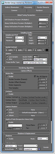
Spatial Contrast values determine when mental ray turns up the number of samples in a particular region of the frame. If the contrast level from one pixel to its neighbor is below the threshold value, mental ray will turn up the number of samples for that pixel to render a higher-quality result for that specific area of the frame. Therefore, the lower the values set for the Spatial Contrast, the higher the sample rate will be (within the Minimum and Maximum levels set).
Rather than setting high sample rates with just the Minimum and Maximum Samples per Pixel, lower the Spatial Contrast values equally for RGBA to force mental ray to use values closer to the Maximum Samples per Pixel value only where it needs to do so.
For example, the image shown in Figure 11-86 was rendered in mental ray with a Minimum Samples per Pixel value of 1/16 and a Maximum Samples per Pixel value of 1 using a Spatial Contrast setting of 0.1 for all four RGBA values. You can see the jagged lines on the wagon’s white decal and edges quite clearly. When the Minimum Samples per Pixel value is changed to 4, the Maximum Samples per Pixel value is changed to 16, and the Spatial Contrast value is changed to 0.04 for RGBA, the render becomes much cleaner, with an acceptable increase in render times (Figure 11-87).
You can get essentially the same quality of render as shown in Figure 11-87 by setting Minimum Samples per Pixel to 16 and Maximum Samples per Pixel to 256 with a Spatial Contrast of 0.07 for RGBA, but with a much longer render time. Achieving quality without very long render times relies first on the Spatial Contrast values (lower is better), and then on the Samples per Pixel (higher is better).
Figure 11-86: A jagged render

Figure 11-87: A clean render

mental ray Motion Blur
Figure 11-88: The Camera Effects rollout

Enabling motion blur in mental ray is quite simple. The Camera Effects rollout, shown in Figure 11-88, is in the Renderer tab of the Render Setup dialog box.
To enable motion blur, simply check the Enable check box in the Motion Blur group. The Shutter Duration value governs how much blur is rendered (the higher the value, the more blur is rendered), and the Motion Segments and Time Samples values set the quality of the blur (higher values give better quality blur, with higher render times).
For practice, try re-rendering the Bouncing Ball exercise from earlier in this chapter with mental ray and motion blur to compare the results from the original scanline rendering.
A popular feature in mental ray is indirect illumination—the simulation of bounced light (explained in the next section). In the tabs at the top of the Render Setup dialog box, click the Indirect Illumination tab. There are three rollouts:
- Final Gather
- Caustic and Global Illumination (GI)
- Reuse (FG and GI Disk Caching)
Final Gather
Final Gather is a method of mental ray rendering for estimating Global Illumination, or GI. In short, GI is a way of calculating indirect lighting. This effect allows for more accurate and physically real lighting simulations, where light can bounce in the scene and cast secondary diffused light on objects. This way, objects do not need to be in the direct path of a light (such as a spotlight) to be lighted in the scene. In short, mental ray accomplishes this by casting points throughout a scene. These light points are allowed to bounce from object to object, contributing light as they go, effectively simulating how real light photons work in the physical world.
This type of rendering can introduce artifacts or noise in the render. Finding the right settings to balance a clean render and acceptable render times is an art form all its own and is rather difficult to master. Only time and experience with Final Gather rendering will lead to mastery.
You will see how to use Final Gather later in the chapter. Figure 11-89 shows the Final Gather rollout. Some of Final Gather’s options, including how to deal with quality and noise, are explained here.
Figure 11-89: The Final Gather rollout in the Indirect Illumination section of the Render Setup dialog box
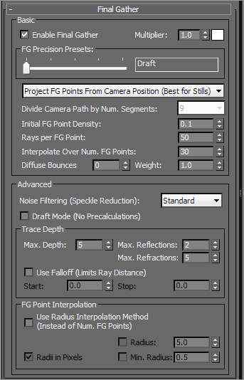
Basic Group
These are the most important parameters in the Basic section of the Final Gather rollout; they set the accuracy and precision of the light bounces, therefore controlling noise:
- FG Precision Presets slider—Sets the accuracy level of the Final Gather simulation by adjusting settings for the renderer such as Point Density, Rays per Point, and Interpolation. These settings alter how mental ray calculates the bounced light. The presets are Draft, Low, Medium, High, Very High, and Custom. (For Custom you enter your own values.) Use this slider first in setting how good your render’s lighting looks. Set it low for tests and increase the precision for final renders. In Figure 11-90, three spheres are rendered with a Draft setting for Final Gather, while Figure 11-91 is set to High. Notice Figure 11-91 is a cleaner render, and also shows more of the background and the spheres than does the Draft quality in Figure 11-90. However, going too high on the Precision slider may incur substantial render times. This slider will adjust the settings for several of the values covered in the following list.
Figure 11-90: A Draft setting produces a test render of the spheres. This image is also included in the color section of this book

Figure 11-91: A High setting produces a much nicer render of the spheres. This image is also included in the color section of this book

- Multiplier/color swatch—This controls the intensity and the color of the indirect light being bounced. A value of 1.0 is the most physically accurate setting and is the default. Reducing this setting will lower the influence of the bounced light in your scene.
- Initial FG Point Density—This multiplier is one of the settings adjusted by the FG Precision Presets slider. Increasing this value will increase the quantity and density of FG “points” that are cast into the scene. For FG to work, the renderer casts these points into the scene. These points of light bounce within the scene and cast light on the objects they encounter. The higher the density of these points, the more accurate the bounced light appears. However, the higher the point density, the longer the render times. You may manually adjust this setting beyond the precision presets set by the slider.
- Rays per FG Point—This value is controlled by the Precision slider, but may also be manually set. The higher the number of rays used to compute the indirect illumination in a scene, the less noise and the more accuracy you gain, but at the cost of longer render times.
- Interpolate Over Num. FG Points—Interpolation is controlled by the FG Precision Presets slider as well as manual input. This value is useful for getting rid of noise in your renders for smoother results. Increasing the interpolation will increase render times, but not as much as increasing the Point Density or Rays values.
Figure 11-92: More diffuse bounces mean more bounced light.

- Diffuse Bounces—The number of bounces governs how many times a point of light can bounce and affect objects in a scene before stopping calculation. If you set the bounces higher, the light simulation will be more accurate, but the render times will be costly. A Diffuse Bounces setting of 1 or 2 is adequate for many applications. Figure 11-92 shows the same render of the spheres as Figure 11-90, but with a Diffuse Bounces value of 5. This render is brighter and also shows color spill from the purple spheres onto the gray floor, though the grayscale image in this book will not demonstrate that adequately. You will find these two images compared in the color section of this book.
- Weight—This value governs how much influence the diffuse bounces have over the lighting solution in the scene. A value of 0 uses no contribution from bounced diffuse light in the scene. A value of 1 uses the full contribution of bounced diffused light, and is the default. This will control the amount of color spilled from one surface to an adjacent surface, such as the purple spill from the spheres in Figure 11-92 and in the color section.
Advanced Group
The Advanced group of settings gives you access to advanced ways of controlling the quality of your Final Gather renders. Some are described below in brief. You should experiment with different settings as you gain more experience with Final Gathering to see what settings work best for your scenes.
- Noise Filtering (Speckle Reduction)—The options are None, Standard, High, Very High, and Extremely High, and the default is Standard. This value essentially averages the brightness of the light rays in the scene to give you smoother Final Gather results. The higher the filtering, the dimmer your Final Gathering simulation result will be, and the longer your render times. However, the noise in your lighting will diminish.
- Draft Mode (No Precalculations)—This setting allows you turn off a good number of calculations that mental ray completes prior to rendering the scene. This will result in a faster render for preview and draft purposes.
Figure 11-93: The Rendered Frame Window now shows several mental ray controls.

- Max. Reflections—This value controls how many times a light ray can be reflected in the scene. A value of 0 turns off reflections entirely. The higher this value, the more times you can see a reflection. For example, a value of 2 allows you to see a reflection of a reflection.
- Max. Refractions—Similar to Max. Reflections, this value sets the number of times a light ray can be refracted through a surface. A value of 0 turns off all refraction.
The mental ray Rendered Frame Window
When you render a frame in 3ds Max, the Rendered Frame Window opens, displaying the image you just rendered. When you render with mental ray, an additional control panel is displayed under the Rendered Frame Window, as shown in Figure 11-93.
This control panel gives you access to many of the most useful settings in the Render Settings dialog box so you can adjust render settings easily and quickly.
Caustics and Global Illumination (GI) Rollout
Within the Caustics and Global Illumination (GI) rollout, you will find controls for various advanced mental ray lighting techniques. Caustics is a visual effect seen when light is reflected off a shiny or reflective surface and onto an adjacent surface in interesting light patterns. Caustics may occur also through a refractive surface, such as a glass of water, so that it indirectly lights an adjacent surface with focused light patterns.
The Global Illumination controls let you control the usage of photons by mental ray for generating Global Illumination. GI is another method of simulating bounced light that offers more options than Final Gather in the way the light is bounced. GI may also be used with Final Gather for a more physically real effect, but at the cost of high render times.
Because this book is an introductory book, we will not be covering caustics or GI.
mental ray Materials
Figure 11-94: Main material parameters for the Arch & Design material.

For the most part, mental ray treats regular 3ds Max maps and materials the same way the Default Scanline Renderer does. However, a set of mental ray specific materials exists to take further advantage of mental ray’s power. In this book, we will examine the Arch & Design material used in mental ray.
The mental ray Arch & Design material works great for most hard surfaces, such as metal, wood, glass, and ceramic. It is especially useful for surfaces that are glossy and reflective, such as metal and ceramic.
To showcase these materials, we will re-texture a few parts of the red rocket from Chapter 7. Figure 11-94 shows the main material parameters for the Arch & Design materials. We will look at the features that we need for the rocket next.
1. Set your project to the mental ray project that you downloaded from the web page. Open the ROCKET_MENTAL RAY_START.max file found in the Scenes folder of the Mental Ray Scene Files project on the companion web page. This file has mental ray already assigned as the renderer. The scene has the room, the rocket’s body, and the thruster already textured. There are no lights in the scene but because Final Gather is enabled, it utilizes the default lights to generate a lighted scene, as shown rendered in Figure 11-95.
2. Open the Slate Material Editor; at the top of the view area you will see the two tabs for the room and rocket. Right-click in the blank area next to the tabs, as shown in Figure 11-96, and create a new view area. Name it More Rocket.
Figure 11-95: The rocket file rendered

Figure 11-96: Create a new view area.

3. Drag an Arch & Design material to the new View area from the mental ray material section of the Material/Map Browser.
4. Double-click on the thumbnail picture of the sample sphere to enlarge in the view area. This will also display the Arch & Design material in the Material Parameter Editor.
5. Name the material Rocket Seat and in the main material parameters ⇒ Diffuse group, click on the color swatch. Change the color to R: 0.0, G: 0.0, B: 0.0 for a pure black color.
6. Leave the Reflection values at their default. This will give the seat a slight reflection.
By default, Arch & Design materials have reflection enabled. The area below the Diffuse group in the parameter section of the Slate is the Reflection group of parameters. Reflections for this material are calculated using the Reflectivity and Glossiness values. The higher the Reflectivity value is, the clearer the reflections are. The Glossiness value controls the blurriness of the reflections from sharp (a value of 1) to completely blurred (a value of 0). When you blur your reflections, the blurrier they are, the noisier they will be in the render. You can use the Glossy Samples value to increase the quality of the blurred reflections once you set Glossiness to anything less than 1.
7. Drag a wire from the material’s output socket to the seat of the rocket in the viewport (Figure 11-97).
Render the Camera viewport to see the new material on the seat. Now we will move on to the fins. There are three fins: two with a white shiny material and one with the decal already applied from Chapter 7. The rocket body and fin are already textured in this scene. To get acquainted with the Arch & Design material, we will texture just a few parts of the rocket.
Figure 11-97: Seat material being applied to the object in the scene

8. Drag another Arch & Design material into the new view area and name it Fin.
9. In the Diffuse group of parameters, click on the color swatch and change the color to white, as shown in Figure 11-98, using these values: R: 1.0, G: 1.0, B: 1.0.
10. Drag a wire from the material output socket to the objects fin04 and fin05 in the viewports. Those are the two white fins on the sides of the rocket.
Figure 11-98: Click the Color swatch and make it white.
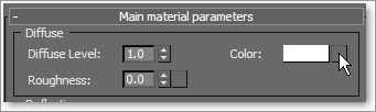
The wheels will be done in the same way as in Chapter 7: by using the Multi/Sub-Object material and dragging the individually created materials to the selected polygons. The difference now is we will use the Arch & Design material instead. The wheel is divided into three materials: shiny red for the bolt, shiny white for the face, and bumpy black for the tire.
If you remember, when we first textured the wheels, we saved sub-object selections in Chapter 7. That will be useful here, too.
1. Select one of the wheels, and go into Polygon mode. Go up to the Main toolbar and click on the Named Selection Sets drop-down menu and choose Wheel_Bolt. This selects the polygons of the bolt (Figure 11-99).
Figure 11-99: The Named Selection Sets drop-down menu

2. In the Slate Material Editor we’ll next create a shiny red material. Drag an Arch & Design material to the view area. Change the Diffuse color to R: 0.8, G: 0.0, B: 0.0 and drag it onto the selected polygons of the bolt.
Figure 11-100: The rocket textured

3. Click on the Named Selection Sets drop-down menu and choose Wheel_White. The white parts of the wheel will be selected. In the Slate, instead of creating a new material, we’ll use the Fin material you’ve already created. Drag a wire from the existing white fin material’s output socket to the selected polygons.
4. Repeat step 3, but select Wheel_Black from the Named Selection Sets drop-down. In the Slate, go to the tabs at the top of the view area and click the Rocket tab. This tab has a few materials already set up for you. Choose the Arch & Design material node called Handle_Bar and drag it onto the selected polygons of the wheel.
5. Repeat the same process (steps 1–4) on the remaining three wheels.
6. Render the camera01 viewport. If it isn’t loaded into a viewport, just select a viewport and hit the C key; this will bring up the Select Camera list. Choose Camera02. The render is shown in Figure 11-100.
3ds Max Photometric Lights in mental ray Renderings
Now that you have had a basic look at the mental ray materials, let’s add some lights to the scene. The idea is to set up a light that makes it appear as though the sunlight is coming through the window, lighting the rocket and the room. In Chapter 10 we looked at lighting using Standard lights, but for this section we will use more advanced lighting tools like Photometric lights and the Daylight system.
Many of the parameters for Photometric lights are the same as or very similar to the Standard lights we looked at in Chapter 10. Here, we will show you the parameters that are specific to Photometric lights. Photometric lights simulate real lighting by using physically based energy values and color temperatures.
1. Either continue with the file you are working with or open the ROCKET_MENTAL RAY_LIGHT.max file found in the Scenes folder of the Mental Ray Scene Files project from the companion web page.
2. In the Main Menu bar, choose Create ⇒ Lights ⇒ Photometric Lights ⇒ Target Light to create a Photometric Target Light.
3. When you click for the Photometric Target Light, you will get a pop-up recommending that you use the mr (mental ray) Photographic Exposure Control, as shown in Figure 11-101. Choose Yes.
4. In the Top viewport, drag to create the light from below the rocket and up (Figure 11-102).
Figure 11-101: mr Photographic Exposure Control warning
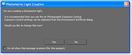
Figure 11-102: Create the light starting in the Top viewport.

5. Switch to the Right viewport and move the light up as shown in Figure 11-103.
6. With the light still selected, go to the Modify panel. The first rollout under the Modifier Stack is Templates. This rollout gives you access to several light type presets to save you time in creating a light. Feel free to play around with the different presets and render the rocket frame a few times to see the differences before continuing with the exercise and the next step.
Figure 11-103: Move the light up in the Right viewport.

Figure 11-104: Distribution (Photometric Web) rollout

7. In the Select a Template drop-down menu, select Recessed 75W Lamp (Web). The “web” is special to Photometric lights and requires some explanation. A photometric light with a “web” distribution essentially defines the light’s behavior and the light it casts. Lighting manufacturers provide web files that model the kinds of lights they make, so using these distribution patterns as templates gives you a lot of options in simulating real world lights, like this 75-watt recessed lamp. Figure 11-104 shows the distribution pattern for this light as seen in the Command panel.
8. We need to take care of some basic stuff now, so with the light still selected, go to the General Parameters rollout and check the Targeted box. We originally created a targeted light but when we used the template it took away the target. Having a target on a light makes it easier to edit the light’s position. Checking this box turns the target back on for the light.
9. Check the Shadows On box to turn it on. In the drop-down menu, choose Ray Traced Shadows.
Figure 11-105: Exposure Control and mr Photographic Exposure Control rollout in the Environment and Effects dialog
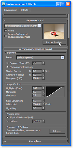
10. In the Main Menu bar, choose Rendering ⇒ Environment. Under the Exposure Control rollout, click the Render Preview button (Figure 11-105). You may notice the preview will show as either very bright or very dark at first. If so, the preview function will work perfectly once you render a frame for the first time.
11. Under the mr Photographic Exposure Control rollout, select Exposure Value (EV), if it isn’t already selected. Set some different values for the EV and see what happens in the Render Preview dialog box. The higher the EV number, the darker the scene will be. Set the EV value to 7 or so and render (see Figure 11-106). You can continue to work with the EV value to experiment with the luminance level. Don’t go too bright in the exposure controls, it might make the scene too washed out. Be sure to set the EV back to 7 and close the Environment and Effects dialog box.
Exposure Controls
Exposure controls adjust output levels and the range of colors of a rendering. These controls are similar to real-world film exposure settings on a physical camera. The mr Photographic Exposure Control rollout gives you the ability to change your rendered output easily without the need for long re-renders.
Figure 11-106: The rocket so far

Photometric Light Parameters
Now let’s look in the Command panel at the Photometric light’s Intensity/Color/Attenuation rollout for our 75W light (Figure 11-107).
Figure 11-107: Photometric light’s Intensity/Color/Attenuation rollout in the Command panel

The Color group of parameters controls the color temperature of the light, which you can set either with a color or in Kelvin degree value just like with real-world photographic lights. In the drop-down menu, there are different color/temp settings. The default is D65 Illuminant (Reference White).
The Intensity group of parameters controls the strength or brightness of the lights measured in lm, cd, or lx at:
- lm (lumen)—This value is the overall output power of the light. A 100-watt general purpose light bulb measures about 1750 lm.
- cd (candela)—This value shows the maximum luminous intensity of the light. A 100-watt general purpose light bulb measures about 139 cd.
- lx at (lux)—This value shows the amount of luminance created by the light shining on a surface at a certain distance.
The Dimming group of parameters is another place to control the intensity of the light. When the Resulting Intensity box is checked, the value specifies a multiplier that dims the existing intensity of the light and takes over control of the intensity. Picking up from the last step in the previous exercise, let’s start to experiment with these values in the following steps:
Figure 11-108: The rocket render with color and intensity changes

1. With the 75W light still selected, go to the Command panel and, in the Color group under the Intensity/Color/Attenuation rollout, click the button next to Kelvin and change the value to 4000. This will give the light a bit more warmth by adding in more yellow/red.
2. In the Dimming group, uncheck the box next to the 100% spinner under Resulting Intensity to enable the Intensity parameter.
3. In the Intensity group, select cd and set the cd amount to 2500. This will brighten things up a bit.
4. Render (see Figure 11-108).
The scene still looks a bit dark and the shadows are very dark; they look like black holes. We will use Final Gather to brighten up the overall render. So far we have just used Final Gather’s default settings. The one thing we need is for the rays that are generated by the light to bounce. The more bounces the light makes, the more luminance in the room. But more bounces slow down the render. It is good to balance bounces with exposure control and the intensity of the light for the best and most efficient result.
5. In the Rendered Frame Window, when you are already rendering with mental ray, the mini Final Gather panel is available for quick changes. Most of these controls also have a home in the Render Setup dialog box, and changing the value in one dialog box updates the corresponding value in the other dialog box. In the mini panel below the Rendered Frame Window (Figure 11-109), change FG Bounces to 7. Render and compare the resulting render shown in Figure 11-110 to Figure 11-108.
Figure 11-109: This mini panel gives you access to Final Gather controls to adjust your render easily.

Figure 11-110: The final rocket

3ds Max Daylight System in mental ray Renderings
The Sunlight and Daylight systems simulate sunlight by following the geographically correct angle and movement of the sun over the earth. You can choose location, date, time, and compass orientation to set the orientation of the sun and its lighting conditions. You can also animate the date and time to achieve very cool time lapse looks and shadow studies. In essence, this type of light works really well with mental ray and Final Gather. We will use it in the most basic way, using all of its defaults.
Figure 11-111: Daylight system

1. Open the ROCKET_MENTAL RAY_FINAL.max file found in the Scenes folder of the Mental Ray Scene Files project on the companion web page. This is the file we ended with after applying the Arch & Design textures earlier in the chapter.
2. In the Main Menu bar, choose Create ⇒ Lights ⇒ Daylight System, as shown in Figure 11-111.
A Daylight System Creation warning will come up, asking you if you want to change the exposure controls to suit the Daylight system. Say Yes to this. See Figure 11-112.
Figure 11-112: Daylight System Creation warning
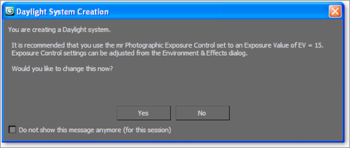
3. In a Top viewport, click and drag at the center of the scene. This will create a compass that is attached to the Daylight system. Make it about the size shown Figure 11-113.
Figure 11-113: Create the Daylight- system compass at about the size shown here.

4. When you release the mouse button, move the mouse so the light is placed outside the walls of the room, as shown in Figure 11-114. The Daylight system is supposed to simulate the sun and sky, so it needs to be outside the room.
5. With the light still selected, go to the Modify panel and in the Daylight Parameters rollout, change the drop-down menus under both the Sunlight and Skylight parameters to mr Sun and mr Sky, respectively (Figure 11-115). When you change the Skylight, a mental ray warning will appear asking if you want to place an mr Physical Sky environment map in your scene. Click Yes (Figure 11-116).
6. Also in Daylight Parameters, under Position select Manual as shown in Figure 11-117. This will allow you to use the Move tool to move the light to where you want it. The default position represents noon. The lower the light is to the horizon in your scene, the more it will simulate darker skies at sunset. We will leave the light in the default position.
7. Select the Camera viewport and render. As you can see, it is too dark. We are trying to simulate a sunny day, and beyond the direct light coming through the window, it’s pretty dark.
Figure 11-114: Light should be outside the room.

Figure 11-115: Change Daylight system light to mr Sun and mr Sky.

Figure 11-116: Add the mr Physical Sky environment map into the scene.

Figure 11-117: Change the light position to Manual.

A good tool to use in this situation is mr Sky Portal. It gives you an efficient way of using a scene’s existing sky lighting within interior scenes that do not require costly Final Gather or GI resulting in very long render times. A portal acts just like a mental ray area light. This light actually gets its brightness and color from the environment already in your scene. With the next step, we continue the example:
Figure 11-118: Move the mr Sky Portal to the window in the wall in the Top viewport.
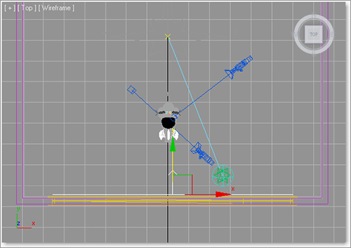
8. In the Main Menu bar, choose Create ⇒ Lights ⇒ Photometric Lights ⇒ mr Sky Portal.
9. In the Front viewport, drag an mr Sky Portal so it fits the window size in the wall. Then in a Top viewport, move the mr Sky Portal back so it is aligned with the opening of the window inside the room, as shown in Figure 11-118. Make sure the arrow is pointing into the room. Render the Camera viewport again. That helps but is not enough; it is still too dark (Figure 11-119). So it’s time to play with exposure controls.
Figure 11-119: Rendering with the mr Sky Portal in front of the window is still too dark.

10. In the Main Menu bar, choose Rendering ⇒ Exposure Control. Click on Render Preview.
11. Under the mr Photographic Exposure Control rollout, change Exposure Value (EV) from 15 (default) to 12, as shown in Figure 11-120. You should see the rendered preview change to show the update. Render the Camera viewport again to see the difference. It looks good but is still a bit dark, so it’s time to add Final Gather bounces.
12. In the Rendered Frame Window mini mental ray controls, change FG Bounces to 5. Render. See Figure 11-121.
Figure 11-120: The mr Photographic Exposure Control rollout

Figure 11-121: Render with Final Gather Bounces set to 5.
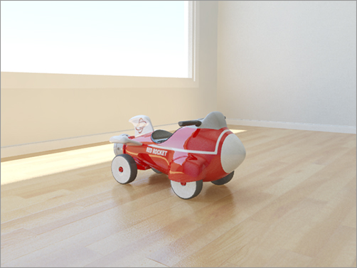
That is it. If you want to play around some more we recommend moving the light for a more dramatic shadow on the floor. Moving the light can have a dramatic effect on the luminance levels too, so be prepared to edit FG Bounces and Exposure Controls also. For this last render, shown in Figure 11-122 and in the color section of this book, we moved the light and changed the Exposure Value setting to 13.
Figure 11-122: The final render

3ds Max Lighting with HDRI in mental ray Renderings
High-dynamic-range images (HDRI) are used in CG to create more realistic scenes than the more simplistic lighting models used.
An HDRI is created when several photos at varying exposures are taken of the same subject, ranging from very dark (underexposure) to highlight only the brightest parts of the scene, to very bright (overexposure) to capture the absolute darkest parts of the scene. When these images (typically five or seven images) are compiled into an HDR image, you get a fantastic range of bright to dark for that one subject or environment.
How does that help you light? mental ray can create an environment map in your scene to which you assign an image, usually an HDRI. That environment map uses the brightness of its image to cast light in your scene.
The best type of image to capture for an HDRI is sometimes called a light probe. This is a picture of an environment such as the office reflected in a chrome ball shown in Figure 11-123. You can also take a light probe using a fish-eye camera lens capable of capturing a field of view of close to 180 degrees.
Figure 11-123 shows the middle exposure of five exposures taken of the same office. Figure 11-124 shows the range of photos from underexposed (dark) to overexposed (bright) that were used to compile this sample HDRI.
In the next exercise we will use an HDRI that is from the 3ds Max default HDRI library installed with the program. See Figure 11-125.
Figure 11-123: A light probe photo of the author’s desk, taken with a chrome ball.
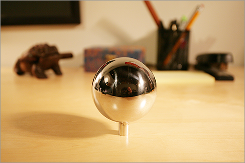
Figure 11-124: The five exposures that make up a sample HDRI of a desk
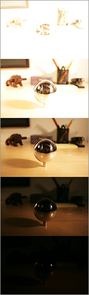
Figure 11-125: HDR image from the 3ds Max default library

Figure 11-126: Add the HDR image in the Environment map.

Open the Soldier_Mental Ray_Start.max file found in the Scenes folder of the mental ray Scene Files project on the companion web page. This scene has the final textured soldier and a tank modeled by Federico Esparza, a student of Randi’s, who was inspired by a tank design from the popular video game Warhammer 40,000: Dawn of War from THQ. There is a flat plane with some cracked dirt texture on it, and the file is set up with mental ray as the renderer. Nothing too fancy, but it’ll get the job done.
1. When the scene is open, in the Main Menu bar choose Create ⇒ Lights ⇒ Standard Lights ⇒ Skylight. Just click anywhere in your scene to create the Skylight.
Figure 11-127: HDRI Load Settings box

2. Next, load the HDRI file into the environment. Choose Rendering ⇒ Environment. In the Common Parameters rollout in the Environment tab, click on the None button under Environment Map, as shown in Figure 11-126. This will bring up the Material/Map Browser.
3. Choose Bitmap from the Standard Maps rollout. Navigate to 3ds Max’s free library in the Maps folder that is installed when you install the 3ds Max 2011 application (typically here: C:Program FilesAutodesk3ds Max 2011mapsHDRs) and select KC_outside_hi.hdr. The HDRI Load Settings dialog box shows up; hit OK (Figure 11-127).
Figure 11-128: The Mapping parameter set to Spherical Environment

Figure 11-129: Skylight parameters

4. The HDRI that is loaded in the environment needs to have its mapping edited. With the Environment and Effects dialog box still open, open the Slate Material Editor, and place the windows side by side. Drag the Environment Map button in the Environment tab to the view area of the Slate Material Editor. This will open an Instance (Copy) dialog box. Click Instance and then OK to load the HDRI map into the Material Editor. Double-click on the HDRI map node to load the parameters. In the Coordinates rollout, select Environ and change the Mapping drop-down menu to Spherical Environment, as shown in Figure 11-128.
5. Select the Skylight and in the parameters, under Sky Color, select Use Scene Environment. This will tell the light to refer to the HDRI loaded into the environment for the lighting (Figure 11-129).
6. Render the Camera viewport (see Figure 11-130), and you can see that all the chrome bits on the tank look pretty good, but overall the scene looks fairly dull. It certainly doesn’t look like it is outdoors in the daytime on a dry lakebed (Figure 11-130).
Figure 11-130: A dry lakebed as an example for the lighting of the soldier and tank

We need more light—specifically, sunlight! The Skylight’s job is to create the indirect illumination. Now, for the sun. With the Daylight system, the scene had both direct and indirect illumination, but the Daylight system doesn’t work with HDRI, so we will need another way of creating sunlight for this scene. For the sun, we can use almost any light that can be directed. We will use the mr Area Spot. These lights work well with mental ray and have parameters very similar to any standard light’s. Shadows are turned on and set to Raytraced by default.
7. In the Main Menu bar, select Create ⇒ Lights ⇒ Standard Lights ⇒ mr Area Spot. To create the light in the viewport, start in the Top viewport and drag from below the soldier and tank and go up, then switch to the Left viewport and move the light up and away from the scene (as shown in Figure 11-131).
Figure 11-131: Place the mr Area spotlight.

8. With the light selected, go into the Spotlight Parameters rollout in the Command panel and check on Overshoot. This causes a spotlight to flood beyond its falloff area, and cast light in all directions. Set the Falloff amount to 90 (Figure 11-132).
Figure 11-132: mr Area Spotlight Parameters rollout

9. In the Intensity/Color/Attenuation rollout, change the Multiplier setting to 0.5. Render the frame and compare it to Figure 11-133. BAM!
With the tank example, the HDRI environment map created an overall fill light for the scene, but also acted as a great reflection environment for the chrome accents on the tank. Adding the extra mr Area Spot light allowed you to create a sunlight for a key light that gave the scene highlights as well as defined directional shadows. HDRI environment maps are very good ways to insert complex lighting scenarios, but are often augmented with standard or photometric lights to really bring out the subject of the scene.
Figure 11-133: The final tank and soldier render

The kind of HDRI map you use will greatly change the effect of the lighting in the scene. Try out some of the other HDRI maps that come with the 3ds Max installation to see how they affect the scene and the reflections in the metal. All these tools and options make mental ray rendering extremely versatile and powerful. This is just the tip of the iceberg; there is much more to experiment with and gain experience on. We encourage you to download HDRIs as well as use different maps that come with the 3ds Max library to see how they change the lighting in any scene.
Rendering is the way you get to show your finished scene to the world, or whoever will stop and look. It enables the vector-created scene to be displayed in bitmap images or movie files on any monitor. Getting to this point in your scene takes quite a bit of work, as you can see, but once you see the results playing back on your screen, it all seems worth it. Nothing is more fulfilling than seeing your creation come to life, and that’s what rendering is all about. However, don’t consider the rendering process merely the last thing to do. Rendering may be the last step of the process, but you should travel the entire journey with rendering in mind, from design to models to animation to lighting. Always allow enough time to ensure that your animations render properly and at their best quality. Most beginners seriously underestimate the time needed to properly complete this step in CG production and don’t allow enough time for the render. Lighting and rendering are so important, as a matter of fact, that lighting professionals (who also handle rendering) are among the most sought-after and highest-paid workers in the entertainment CG field.
In this chapter, you learned the basics of rendering with Autodesk 3ds Max 2011. You began by learning about render output and the types of files to which you can render. You rendered the Bouncing Ball exercise from Chapter 8 and enabled motion blur for heightened effect. Then you learned about cameras and rendering separate passes with Render Elements. Additionally, you learned how to render glows and how to use raytracing to render true reflections and refractions in a scene. You put all that to good use in rendering the Red Rocket project that you’ve worked on throughout the book to a 1.5-second QuickTime file. Then you moved on to various exercises to explore Final Gather and HDRI when rendering with mental ray.
After you have rendered many more scenes, you’ll have a much better understanding of how to set up your scene from the very beginning to efficiently achieve a great result. It won’t hurt to go over the examples in this chapter more than once and try to render your own scenes in different ways.