14
Deployment Topologies, High Availability, and Disaster Recovery
In today’s modern and cloud-native software world, you would think that it would be easy to simply click and deploy software. Amazon Web Services (AWS) made the public cloud ubiquitous. AWS made it easy for developers and enterprises to deploy their software and services pretty much anywhere in the world. The advent of microservices is supposed to make software easier to develop, deploy, and run. Also, Kubernetes and containers made delivering code and software even easier.
The old days of worrying about architecture and non-functional requirements such as High Availability (HA), multi-tenancy, and even Disaster Recovery (DR) are things of the past. However, this is not the complete truth: the new era of cloud computing, cloud-native, and cloud-ready software brings different and new challenges to these old-age concerns.
In this chapter, we will look at the following topics in the context of Cloud Pak for Business Automation (CP4BA):
- Deployment topologies
- High availability
- Disaster recovery
Problem statement
As an enterprise architect for a company-wide shared service platform, I need to support multiple Lines of Business (LOBs) for their mission-critical applications and solutions that leverage CP4BA capabilities. Each of these LOBs has an application development team, different Service-Level Agreements (SLAs), and the same non-functional requirements since they are classified as tier 1 applications (business-critical applications). In this chapter, we will learn about the different deployment topologies and determine which would meet our requirements. Additionally, we will look at the HA and DR options to meet the requirement for the company’s tier 1 application.
Deployment topologies
Before we can look at the deployment topologies for CP4BA, we need to understand the platform CP4BA runs on: Red Hat OpenShift. As mentioned in the problem statement, the enterprise has a shared service platform that is built on OpenShift.
OpenShift is built on Kubernetes, which is the backbone of the platform that deploys and runs CP4BA. Kubernetes (k8s) was originally designed by Google to help improve and expedite software deployment. k8s, with the help of the Cloud Native Computing Foundation (CNFC), has become the de facto standard for running containers. Kubernetes and containers take virtualization to the next level to help improve resource utilization through the k8s scheduler. Additionally, as part of k8s’ best practices to define resource requests and limits, such as CPU, it prevents containers from overutilizing resources. This is not the case when running applications as processes on a virtual machine. Hence, application to a virtual machine is high to ensure critical applications get the needed resources without contentions from other applications. This decreases the density of applications on the same hardware compared to k8s and containers. It is very common for OpenShift customers to run hundreds to thousands of applications in a single OpenShift cluster as a shared container platform.
Now that we understand the scale at which OpenShift can support and the common usage pattern for it, we can look at the deployment topologies for CP4BA on OpenShift. CP4BA itself also depends on what IBM calls Cloud Pak Foundation Services (CPFS), formerly known as Common Services (CS):

Figure 14.1 - CP4BA high-level deployment architecture
Here is a list of terms from the preceding diagram:
- IAM: Identity Access Management
- BTS: Business Team Service
- Licensing: Licensing Service
- Zen: Cloud Pak common web UI
- ES: Elasticsearch
- Flink: Apache Flink
- Kafka: Apache Kafka
- ADP: Automation Document Processing
- Content: Content Services (FileNet)
- ADS: Automation Decision Services
- Workflow: Business Automation Workflow
- Applications: Business Automation Application
- ODM: Operational Decision Manager
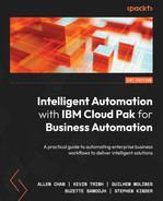
When you deploy an instance of CP4BA, it is deployed into a Kubernetes namespace or, in OpenShift terminology, a project. The namespace or project is a relative way to isolate a deployment for a given application group or LOB. It provides role-based access control so that it is managed and administered by the right set of people. Also, it provides the OpenShift cluster administrator with an easier way to manage what teams or groups own what applications, allocate and constrain resources to a namespace, manage security, monitor usage, and so on based on the namespace. The namespace scope deployment provides the flexibility of deploying multiple instances of CP4BA for different LOBs on the same OpenShift cluster. The only exception to this is CPFS. CPFS is installed in its own namespace but it is currently shared across all Cloud Pak instances:

Figure 14.2 - CP4BA deployment approach
Here is a list of some new terms from the previous diagram:
- IAF: IBM Automation Foundation
- IAF Core: IBM Automation Foundation Core
- IAM: Identity and Access Management
- Metering: Licensing Service
- ODLM: Operand Deployment Life Cycle Manager
This deployment topology gives us flexibility in ensuring that one deployment of CP4BA for a LOB does not impact another deployment for another LOB. Also, it allows the CP4BA administrator to control the maintenance of each of the deployed instances. Again, the only exception is CPFS since it is shared. Patching or upgrading CPFS will apply those changes to all Cloud Pak instances since there is only one and it is shared. Also, this deployment approach provides a consistent and repeatable process that we can automate to higher environments such as test, pre-production, and production. This is the recommended deployment approach.
An alternative approach to the latter is combining development and test environments into a single cluster. Customers who decide on this approach have resource constraints and need to optimize their cluster utilization. This would warrant a much larger OpenShift cluster to also support different deployment instances of CP4BA for different LOBs. The drawback of this approach is that patching or upgrading CPFS has a greater impact if something goes wrong. Also, the steps for the initial buildout and deployment for pre-production and production are now different. This also includes the patching or upgrading process. Here is a diagram for the alternative deployment approach:
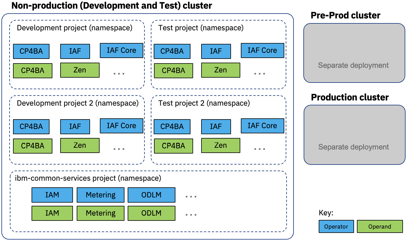
Figure 14.3 - CP4BA alternative deployment approach
Notice that in either approach, we are sharing an OpenShift cluster with other deployments and the underlying resources. What are the options when you need more isolation? There are various deployment methods and architectures that can be incorporated into the desired level of isolation required by the application. For example, there are cases or requirements where customers want to have a dedicated cluster for a single deployment to ensure complete isolation and minimize the impact on a mission-critical application. This is the opposite end of the isolation spectrum. As you move from a shared to a dedicated cluster, the greater the resource cost, maintenance, and administration cost:
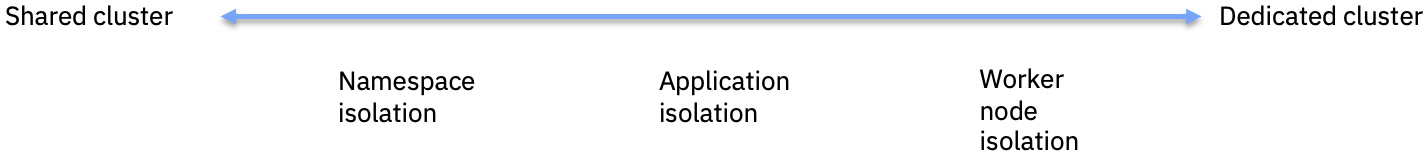
Figure 14.4 – Deployment isolation
In this section, you learned that you have different options when it comes to deploying CP4BA on OpenShift. The option you choose is either dictated by the OpenShift administrators, who provide the shared platform service, or the requirements by the LOB, who owns the application. Those requirements determine the level of isolation that drives the deployment pattern. But the most common and recommended deployment pattern is isolation at the environment level, such as development, test, and so on.
High availability
HA is a concept and practice that hasn’t changed even today. A highly available system provides an agreed level of uptime or SLA. HA is the ability to withstand planned and unplanned outages and to provide continuous processing of business-critical applications. Enterprises have always measured availability or uptime in terms of 9s. In the past, most enterprises considered achieving five nines or even four nines nirvana. According to Dunn and Bradstreet, 59% of Fortune 500 companies still experience a minimum of 1.6 hours of downtime per week. And according to TechChannel, based on the ITIC survey for 2021, the average cost of an hour of downtime on average is over $300,000. Are four nines – that is, 52.56 minutes of downtime per year – even achievable? Take a look at the following table for clarification about the number of 9s:
|
Level of Availability |
Downtime Per Year |
|
90% |
36.5 days |
|
95% |
18.25 days |
|
99% |
3.65 days |
|
99.9% (three nines) |
8.76 hours |
|
99.95% |
4.38 hours |
|
99.99% (four nines) |
52.56 minutes |
|
99.995% |
26.28 minutes |
|
99.999% (five nines) |
5.26 minutes |
|
99.9999% (six nines) |
31.5 seconds |
Table 14.1 – Level of availability
Typical HA design patterns comprise systems that provide redundancy for component(s). One approach is to implement a failover solution such as active-passive (cold standby) or active-passive (hot standby). Another solution is to implement an active-active HA architecture. This provides the highest level of uptime, as well as scalability. When looking at individual components, such as databases, it is possible to achieve maximum availability by implementing an active-active architecture for the component, such as Oracle Real Application Cluster (Oracle RAC) or IBM DB2 pureScale. Other components, such as web applications deployed on IBM WebSphere, provide an active-active architecture via application server clusters:

Figure 14.5 – IBM WebSphere network deployment application server cluster
An active-active architecture becomes much easier when deploying CP4BA on OpenShift using containers. A Kubernetes platform, such as OpenShift, provides a highly scalable and highly available architecture. A typical standard OpenShift cluster provides redundancy for all its components, such as the master control plane, ingress or proxy, and so on:

Figure 14.6 – OpenShift cluster
A k8s deployment descriptor allows you to specify how many instances or replicas (replicas: x) of the same component a deployment should have to provide HA and workload support:

Figure 14.7 – Kubernetes deployment replica
The k8s scheduler handles the deployment based on the deployment descriptor. CP4BA components can easily be configured to have multiple replicas as part of the deployment. This can be done by modifying the Custom Resource (CR) definition for the individual components, such as FileNet Content Platform Engine. The medium workload profile that can be defined in the CR provides support for medium-sized workloads but also HA by having multiple replicas for each of the CP4BA components by default. The workload profile change would also propagate down to the underlying dependent services, such as IAF and CPFS.
k8s provides other OOTB feature capabilities that also help increase availability and resiliency for CP4BA deployed applications. CP4BA applications that are deployed on OpenShift automatically enable these resiliency features as part of a standard deployment. One such feature is pod anti-affinity, which can be defined in the deployment descriptor. This setting tells the scheduler to not place the pod of the same application on the same node. This setting can be strictly enforced by making the affinity rule required versus preferred. In contrast to the traditional WebSphere cluster, the administrator needs to define the application cluster upfront as a horizontal cluster. The placement of the application instances is fixed in most cases when creating and defining the cluster. The exception to this is using a WebSphere dynamic cluster. However, this is also fixed and constrained to the predefined nodes and instances that comprise the dynamic cluster.
Another important feature that helps ensure the availability of the application is the livenessProbe. This is essentially a health check configuration at the container level that ensures the application is healthy. The livenessProbe can be configured in different ways to test the health of the application. This is a drastically different and big improvement when compared to the traditional WebSphere. Even the best and most well-designed applications occasionally suffer from unresponsiveness for one reason or another. When this occurs, the affected application server instance impacts the users served by this instance, which exhibits a long wait for a response or the infamous hourglass or spinning wheel commonly seen on web applications. Eventually, the problem starts to manifest itself in other application instances and causes a complete outage. With the k8s livenessProbe configured, this event would not happen since the livenessProbe would fail and the kubelet process would kill the container and spin up a new, fresh, healthy one.
With this, technology and software have drastically improved so that achieving four nines is potentially possible. What is also helping enterprises increase the availability of their applications is the adoption of public clouds such as AWS and IBM Cloud. The public cloud brought new standards in terms of application deployment architecture and service availability. AWS (https://aws.amazon.com/compute/sla/) and Azure (https://azure.microsoft.com/en-us/support/legal/sla/virtual-machines/v1_9/) have SLAs for their virtual machine instances such as the AWS EC2 uptime SLA, which is four nines. The reason for this great achievement is the introduction of AWS Availability Zones (AZs). With AWS AZs, the Single Point Of Failure (SPOF) for the data center is a thing of the past. AWS first introduced AZs for some of its services, such as AWS Relation Database Service (RDS), back in 2008. AZs provide applications and services with the ability to achieve the next level of active-active HA. AZs have become the standard and requirement when looking at running applications or using public cloud services:
Figure 14.8 – AWS AZs
OpenShift can take advantage of public cloud AZs to provide similar availability as public cloud services. OpenShift, when installed on the public cloud, can spread its components, such as the master control plane, across AZs. But the requirement is that there must be at least three AZs for the master control plane and other components to have a quorum:

Figure 14.9 – OpenShift cluster across three AWS Availability Zones
Enterprises can combine a public cloud service, Platform-as-a-Service (PaaS), and OpenShift to run CP4BA. For example, they can use public AZs to deploy OpenShift, LDAP as a service such as AWS or Azure Active Directory, Storage-as-a-Service (STaaS) such as AWS Elastic File System (EFS) or Azure Files, and Database-as-a-Service (DBaaS) such as AWS or Azure PostgreSQL to provide the ability to achieve four nines or close to it.
But not all enterprises can or are willing to adopt the public cloud. One reason is regulatory or compliance requirements for where the data can reside. Some industries or enterprises won’t or are not willing to store data in the public cloud. Hence, some enterprises are starting to replicate what the public cloud made standard with AZs. Enterprises are looking to build multiple data centers within a metropolitan city to provide redundancy. Data centers are distributed across the metro city, stretching between 10 to 30 miles and connected by a redundant high-speed network. Network latency between these data centers is as low as 2 milliseconds. This brings public cloud-like capabilities to the enterprise. OpenShift can be deployed in what Red Hat calls a stretch cluster or a metro cluster. The requirements for this OpenShift stretch cluster are what make it difficult for an enterprise to deploy. Similar to deploying OpenShift across AZs in the public cloud, it requires at least three data centers. This alone makes it difficult for enterprise customers to implement the OpenShift stretch cluster. Nowadays, enterprises are starting to have two data centers that are close by, but three is very rare. There are instances where customers have deployed the OpenShift stretch cluster. But according to Red Hat’s guidance for deploying an OpenShift cluster that spans multi-sites, it is not something Red Hat recommends (https://access.redhat.com/articles/3220991).
So, HA is critical to all enterprises, and not having it means increasing loss of revenue, which has increased in the past years. HA has evolved and so has enterprises’ HA architecture. This is mainly the result of new technologies such as Kubernetes and OpenShift and the maturity of infrastructure for data centers thanks to the advent of public clouds such as AWS. Combining these technologies and services provides enterprises with the option to deploy CP4BA and the means to achieve four nines or better.
Disaster recovery
HA is not DR. They have similar objectives: business continuity and minimizing downtime. The difference between HA and DR is that DR focuses on policies and procedures to enable the recovery of the system, application, or entire data center to a fully operational state after a catastrophic event. Similar to HA, there are SLAs that help define requirements for DR, which, in turn, determine the policies, procedures, strategy, and even implementation details to meet the needed SLAs. Two important terms help define the DR requirement: Recovery Point Objective (RPO) and Recovery Time Objective (RTO).
RTO measures how quickly the system, application, or data center can be restored. This measurement of time for recovery is not only about restoring the application to a functional state to resume critical business processes but also about the data.
RPO is the enterprise measurement of data loss tolerance. How much data can the enterprise afford to lose without it having a significant impact on the business? Here is a diagram for a quick comparison of RTO and RPO:

Figure 14.10 – RTO versus RPO
As mentioned earlier, the RTO and RPO requirements will determine the process, procedures, and strategy needed to support those requirements. For example, requiring an RPO of zero, which means no data loss, requires different infrastructure and implementation details that are going to be vastly different from an RPO of 4 hours. That is also true for RTO. Requiring an RTO of 1 or 2 hours is going to require a different process and build out of DR than, say, 8 hours. The DR environment almost needs to be in a hot standby mode to achieve 1 or 2 hours. At the time of writing, CP4BA can only support an active-passive DR architecture. This entails two independent OpenShift clusters – one in the primary site and another in the DR site.
But before we can determine what is feasible from an RTO and RPO perspective, we need to understand the overall landscape, including the data tier. DR is not only about restoring the business needs for the CP4BA application but ensuring that the data is also available and consistent. The CP4BA data landscape has two primary persistent datasets. The first is the database, while the second is at the storage level. We will look at the Business Automation Workflow (BAW) data landscape as an example since it also includes FileNet. The following table provides the data landscape for both BAW and FileNet:
|
What to Protect |
Traditional Backup and DR |
CP4BA Backup and DR |
|
Data in databases (FileNet CPE, BAN, BAW, and so on) |
|
|
|
Configuration files |
|
|
|
Document storage |
|
|
|
Persistent files |
|
|
|
Transaction logs |
Transaction log in the database |
Transaction log in the database |
|
Lucene/PFS data |
Rebuild the Lucene data on the DR site |
Rebuild PFS data on the DR site |
Table 14.2 – Backup and DR for traditional BAW versus CP4BA BAW
Now that we understand what the data landscape looks like for BAW, we also need to understand the data flow and how it impacts what we are doing from a backup and replication perspective for each of the persistent layers. The primary use case for BAW is workflow or process-centric and the data flow mainly comprises the databases. The databases must be backed up and replicated using database vendor-recommended approaches and best practices. Since we are dealing with multiple databases for BAW, it is also important that the database’s backup and replication are in sync and consistent with each other. This will vary, depending on the database vendor. For example, IBM DB2 provides a feature capability that allows database write suspends to occur before an online backup is done. Issuing a write suspend and performing an online backup allows for a quick backup of all BAW databases. Additionally, ensuring that all the databases are under the same High Availability Disaster Recovery (HADR) control ensures that all databases’ replication to DR is in sync. Oracle databases and other CP4BA-supported databases have similar capabilities. The ability to have async versus sync database replication will have an impact on RPO.
There are other databases in play here as well that are part of the dependent services, such as CPFS. BTS uses Postgres, whereas IAM uses MongoDB. The databases from these services don’t have the same backup and replication support as DB2 or Oracle. These databases must be backed up, and their backups are stored externally to be used for restoration in DR. This means that the lowest RPO is dictated by the interval of this backup schedule.
The other use case for BAW involves the inclusion of document data that is persisted in the storage layer. The BAW process can be initiated from a document being added to the FileNet content repository or as a step in the process flow. This means that the database needs to be in sync with the document storage. It would be bad if the DR process had data consistency where, after DR failover, casework resumes the case process he/she was working on and is unable to retrieve the case documents. The FileNet content storage has many options, including persisting in the container storage. The document content can be stored in filesystem storage such as OpenShift Data Foundation (ODF), IBM Spectrum Scale, NetApp Trident, or other storage vendors certified by OpenShift. Additionally, the document could also be stored in object storage, such as IBM Cloud Object Storage (ICOS) or NetApp StorageGrid.
Similar to databases, the storage utilized for the FileNet content store will determine the backup and replication capability. One thing to keep in mind is that the content store will continue to grow and become very large, in the terabytes range, in a short period, depending on the use case. This means that backing up the storage or replicating it could be an issue if the storage being used doesn’t support block-level snapshots or replication. At the time of writing, using ODF as the underlying storage for CP4BA will require additional software, such as IBM Spectrum Protect Plus, to provide backup and replication support. IBM Spectrum Protect Plus can take backup snapshots of the ODF persistent volume claims to a vSnap server and replicate them to a DR vSnap server. This method does have limitations that impact RPO since the SPP SLA backup policy for storage is every 6 hours. In contrast, you can use storage appliances such as NetApp or EMC, where block-level snapshots take seconds and replication takes minutes:

Figure 14.11 – CP4BA DR using IBM Spectrum Protect Plus
This is where using cloud object storage such as ICOS or AWS S3 is a better option when it comes to backup and DR. Nevertheless, what is important from a data consistency perspective is that the database backup and replication processes need to be ahead of the content storage backup and replication processes. It is better to have more content in storage than to have database records pointing to missing content. But using cloud object storage will only solve the content storage for FileNet, not all the storage needed by other components for CP4BA.
Keep in mind that we have only been looking at CP4BA. If CP4BA integrates with other applications or backend systems, these applications’ or systems’ data needs to be considered as well as part of the complete data landscape. These applications or systems might have their own data backup and replication requirements that will impact the overall RPO.
So far, we have primarily looked at factors that impact RPO. Now, we will focus on factors that impact RTO.
Remember that RTO is about how long it takes to bring back the CP4BA environment to continue business transactions. At the time of writing, CP4BA only supports active-passive DR, so this limits the process that can be applied. In terms of the DR environment setup, to reduce the RTO time, the DR environment is fully deployed but scaled down so that storage and database replication can occur. This is also to prevent any potential writes that could cause data to be inconsistent while the primary site is still active.
The key to setting up DR is that it is configured identically and points to the same data as the primary, but also the replicated instance. This also applies when changes such as maintenance updates or configuration changes to the primary are applied to DR. With the DR environment set up and configured, when DR is initiated, it is a matter of syncing the data between the database and storage rather than scaling up the CP4BA deployment. With automation, these processes can complete in a couple of hours or even less:
|
DR Event |
High-Level DR Procedures |
|
Initial DR site setup |
|
|
DR failover |
|
|
DR failback |
|
Table 14.3 – CP4BA BAW DR procedures
Similar to RPO, some other factors and processes may also need to occur as part of the overall DR process, such as DNS updates, other applications, or backend systems that CP4BA integrates with.
Now that we have an overall view of the CP4BA DR requirement, we can look at the potential SLAs for RPO and RTO. First, let’s cancel out the obvious: an RPO of zero. With the current DR requirement of active-passive and the dependencies of data replication for both storage and database, the potential best scenario is 15 to 30 minutes, depending on the storage replication technology and network latency. The potential best RTO is a couple of hours if we’re purely talking from a CP4BA perspective. Remember that there are potentially other factors and dependencies that could impact both RPO and RTO.
Summary
In this chapter, we learned that CP4BA has an adaptable deployment topology that can meet different applications and LOBs requirements. However, the recommended deployment strategy is for each deployment for development to be isolated by namespaces and clusters. This provides a repeatable and consistent deployment architecture that is carried out in higher environments.
Additionally, CP4BA leverages and deploys with HA in mind when it is deployed on Red Hat OpenShift. OpenShift can be made highly available and resilient by leveraging the public cloud and AZs. Lastly, we learned that DR is dictated by our requirements around RPO and RTO. RPO is primarily driven by the technology used for storage and database, whereas RTO is primarily driven by CP4BA support for active-passive only DR.
The next chapter describes a technique that can be used to automate the setup, daily operations, and maintenance of automation solutions.