
7
Workflow for Process Automation
Even though RPA stands for robotic process automation, it is more about task automation, which means helping a worker to perform their tasks. On the other hand, when we want to create an intelligent automation solution that involves multiple workers and systems, we need something that can oversee the orchestration of many activities. This is where workflow automation comes in.
Workflow is about the orchestration of activities that can be performed by humans, robots, and systems. In this chapter, we will use workflow automation to manage a business process of an organization. We will also investigate how RPA bots can work collaboratively with Task and Knowledge workers to maximize efficiency.
Specifically, we will cover the following main topics:
- Discussing the problem statement
- Building your process flow with a workflow designer using BPMN
- Integration with external services
- Allowing humans to work with your process through the task UI
- Interacting with RPA bots through the task UI or direct invocation
- Managing the process life cycle, deployment, and packaging
- Several advanced topics such as escalation, exception handling, and troubleshooting
Technical requirements
The source code of this chapter can be found on GitHub at https://github.com/PacktPublishing/Intelligent-Automation-with-IBM-Cloud-Pak-for-Business-Automation/tree/main/Chapter%207.
Problem statement
Request and Approve is a very common workflow automation pattern in any intelligent automation solution.
In a typical Request and Approve workflow, we perform the following steps:
- Person A submits a request.
- Based on the information, the request will be routed to Person B for review and approval.
- After the approval is granted or denied, the request will then be routed to Person C to work on (if approved) or routed back to Person A with the result.
This typical pattern can be applied to multiple use cases such as the following:
- Invoice processing
- Insurance claims processing
- Bank loan applications
- Various human resources processes
In this chapter, we will implement a simplified version of the hiring process, as shown in Figure 7.1:

Figure 7.1 – Request and Approve workflow for position request
- Here, a hiring manager will submit a request for a new job position.
- The request will then be routed to the general manager for review and approval.
- Once the request is approved, human resources will start the hiring process by selecting a set of potential candidates for interview.
A real hiring process will include more steps, for example, the subsequent interview of the candidates by the hiring managers or the creation of the hiring contracts. For the purpose of building a workflow solution, it is generally easier to start from a basic business process and iteratively evolve it to handle more use cases.
We will go through the major steps in building a workflow automation solution:
- Building the workflow process
- Building the task UI
- Integrating with external services
- Working with users
- Packaging and deployment
Building the workflow process
In this section, let us understand how to build the workflow process.
To get started, we will create new workflow automation within the Business Automation Studio by selecting the Workflow automation option in the Create dropdown, as shown in Figure 7.2:
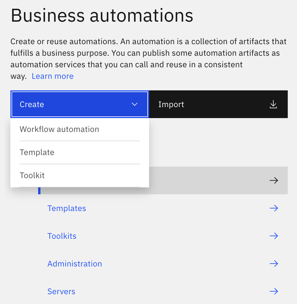
Figure 7.2 – Creating new workflow automation
For this example, we will just create workflow automation by providing the name, Hiring Process, and a brief description of the purpose of this workflow automation:

Figure 7.3 – Creating new workflow automation – hiring process
Once the workflow automation project is created, you will be directed to the Process App Settings page of the Hiring Process application (Process App).
Within the Process App Settings page, there are three major tabs:
- Overview
- Environment Variables
- Servers
The following screenshot displays those three tabs:

Figure 7.4 – Hiring Process – Process App Settings
Let us discuss these tabs in detail:
- Overview: Figure 7.4 describes the general settings of the project and provides information that would be relevant for users of this project, such as the following:
- Common: This allows us to specify the name and purpose of this application.
- Authorization Settings: This allows the automation developers to specify Process application administrators that can control the life cycle of this process application, such as starting and stopping a particular running process.
- Exposed Items: This contains the set of capabilities that are considered external and can be started directly in IBM Workplace or can be called by applications running outside of this workflow automation.
- Coach Designer Settings: This allows the automation developers to change or customize the look and feel of the task user interfaces.
- XML Settings: This allows us to customize the namespace for any exposed web services. We should keep the default settings in most situations.
In addition to the Overview section, there are two other sections:
- Environment Variables: This allows us to specify values that can change depending on the deployment environments of the applications, such as timeout values and business variables. This is a powerful concept that allows automation developers to account for differences between different target environments, different timeout values between QA and production, or even different business logic.
- Servers: This is like environment variables but we are grouping the different values related to how to connect to an external service per environment.
In most cases, automation developers can start with the default values in the preceding settings. In the next section, we will create our first business process.
Creating the first process
To get started, we will first create a process to describe the logical flow of the hiring process:
- To do that, we will move to the Processes tab on the left navigation panel and select the New | Process options, as shown in the following screenshot:

Figure 7.5 – Creating a new process
- In this case, we will call the new process, Request New Position:

Figure 7.6 – Creating a new process – Request New Position process
- Right after that, the designer will be switched to the Request New Position process view where we will see the default process that got created. The default process is composed of three activities:
- Start: The starting point of the process.
- Inline User Task: This is different from a regular user task in that the UI will be automatically generated based on the inputs and outputs of the task. This allows the automation developers to quickly prototype the business process without having to worry about designing the UI.
- End: The endpoint of the process. Once a process reaches the End activity, it is considered completed:

Figure 7.7 – Default process
One of the key advantages of the low code workflow automation design experience is its ability to run the process at any time without having to write a single line of code or set up any CI/CD pipeline integration. Even now, if you press the play button, the designer will run the newly created process and bring up the built-in process inspector.
In the process inspector, you will see information such as follows:
- The process instance ID (1135)
- Its name (Hiring Process)
- Its status (Active), and various other information
It also highlights the current process is stopped at the Inline User Task activity. The process is stopped at the activity because it is waiting for a response from the user.
All this information is shown in the following screenshot:
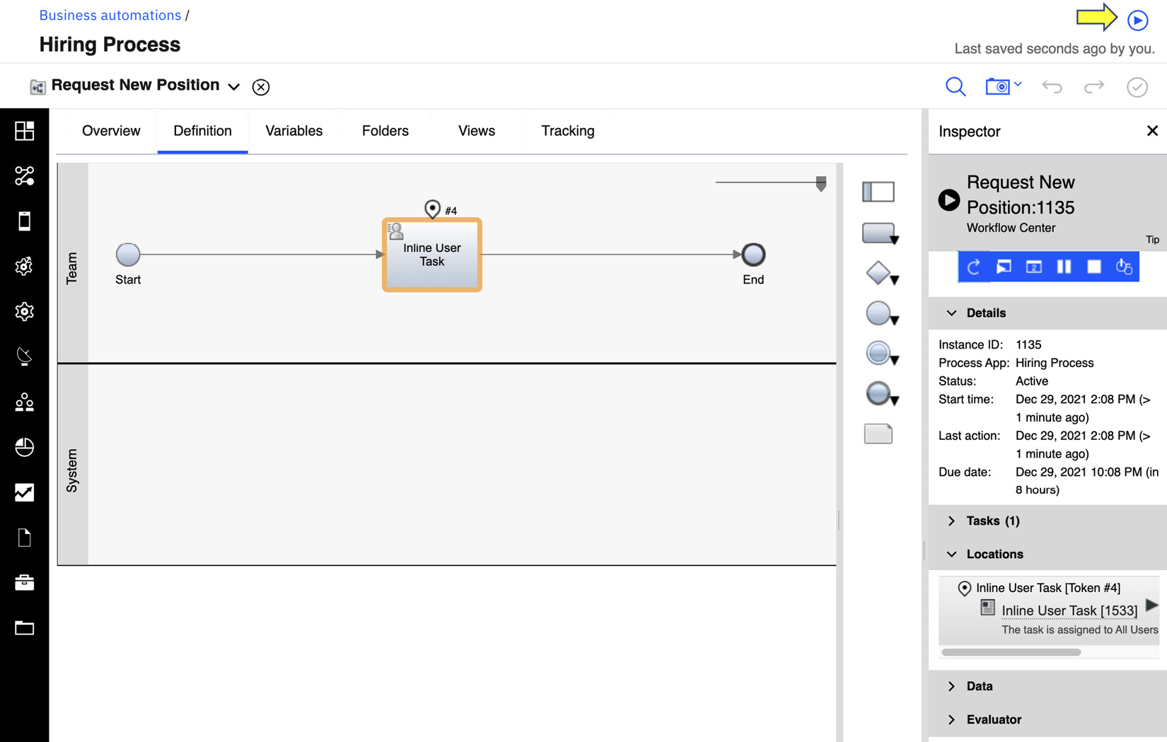
Figure 7.8 – Running the default process with built-in Inspector
To work on the task, we can claim the task by pressing the play icon right next to the task in the Inspector view:
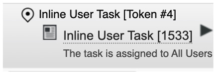
Figure 7.9 – Claiming the Inline User Task
This will in turn bring up the generated Task UI. At this point, given this is the default process, there is nothing of interest as we have not specified any inputs and outputs of the activities.
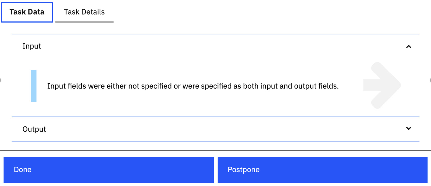
Figure 7.10 – Generated UI for the default “Inline User Task”
The only thing we can do is to press Done and complete the task, which will also move the process to the end activity and complete the process.
Adding swimlanes and completing the process diagram
If we review the scenario, there are three distinct personas participating in the automation:
- Hiring manager
- General manager
- Human resources
Each persona in the solution is represented by different swimlanes in a BPMN diagram.
There are two default swimlanes to start with:
- Team (for user tasks)
- System (for system tasks)
We will repurpose the first swimlane and rename it for Hiring Manager:
- We can do that by selecting the swimlane, and in its Properties panel, changing its name to Hiring Manager. In our example, we will also change the color to better distinguish the different swimlanes:

Figure 7.11 – Modifying the swimlane for “Hiring Managers”
- To add more swimlanes, right-click on the first swimlane and select the Create lane below menu option:

Figure 7.12 – Adding swimlane
- We can follow the preceding steps to create two more swimlanes, one called General Manager and one called Human Resources. In addition, we will create two new user tasks by dragging the task icon (
 )from the palette on the right to the respective swimlanes.
 - We will name the first task Review New Request and the second task Find Candidates. At this point, we should have three tasks, but they are not connected:
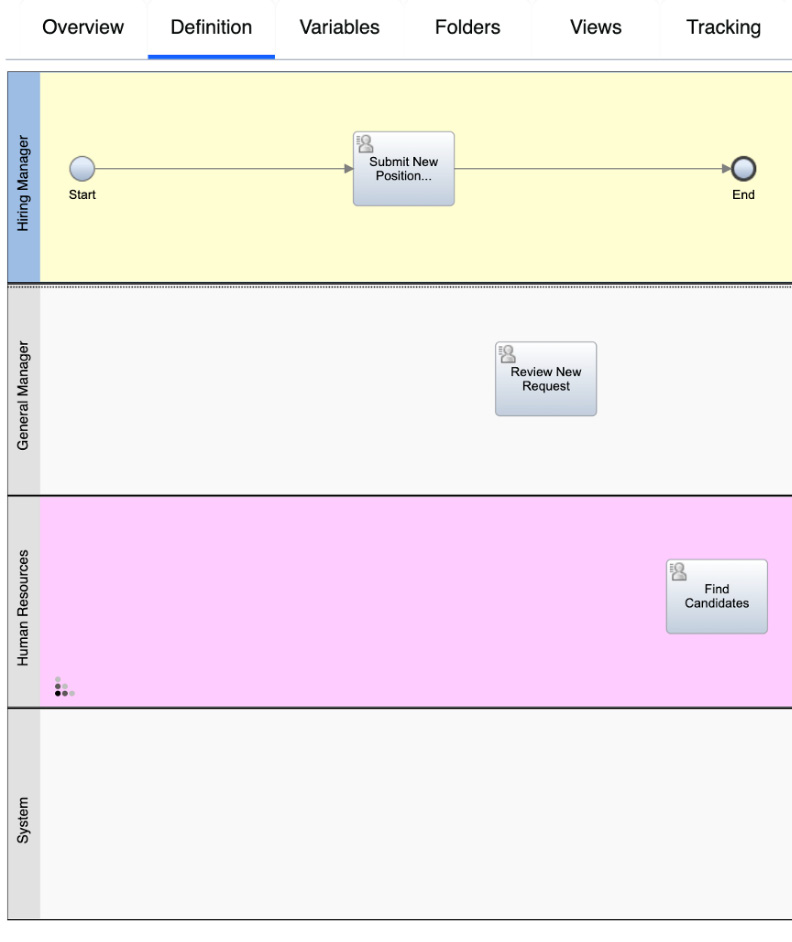
Figure 7.13 – Incomplete process diagram for “Request New Position”
- For the process to be meaningful, we should connect the tasks together to indicate the business flow logic. We can do that by selecting the wire between the Submit New Position Request activity and the End activity and dragging it to connect to the Review New Request activity:

Figure 7.14 – Drag-n-connect wire from one activity to another
- We can then connect from Review New Request to the Find Candidates activity. However, before we can do that, we need to add a decision logic by adding an Exclusive Gateway (
 ). Exclusive Gateway is like an If-Then-Else statement in regular programming language and it signifies branching conditions within a process flow. For now, we can leave the default settings.

Figure 7.15 – Complete process diagram for Request New Position
- We have now defined our simplified hiring process in BPMN notation. What the preceding diagram tries to describe is a simple business process where the hiring manager can initiate the process by creating the Submit New Position Request task.
- Once the request is submitted, it will be routed to the general manager, where they can review the request through the Review New Request task, and depending on their decision (GM approved?), the request will either be routed to human resources to find candidates or to End. We can try out the process by using the play mechanism described earlier to validate the logic flow is matching the expectation.
However, in a real-world situation, we will need to provide more details for the process to be meaningful, for example, who are the hiring managers, how do you make a position request, and how do we save all the collected data?
We have three groups of people that can participate in this process, which means we want to make sure we will only assign the tasks to people who can work on the tasks, and only people that are authorized to work on certain tasks can claim them; for example, we do not want hiring managers to be able to approve their own requests. To do that, we will need to set up the team assignment for each swimlane by creating three different teams:
- Hiring Managers
- General Managers
- Human Resources
Let us see how to set them up:
- In the Team section on the left navigation panel, select the Teams | New | Team options:

Figure 7.16 – Creating a new Team
- This will open the Team Settings panel. In Team Settings, there are four sections:
- Common: This provides documentation to describe the purpose of this team.
- Behavior: This identifies how we will determine the membership of this team. If we select Users or groups, we will determine the membership based on the list of selected users or groups in the Members section. If we select A service, the membership will be calculated at runtime by calling a special Team Member service. In this example, we will use the simpler Users or groups setting. However, in a more complicated scenario, we can use Team Member service to create dynamic teams that can change based on other available information (locations, time zone, and so on).
- Members: This selects the specific Users and User Groups that will be part of this team. The special tw_allusers group can be used to represent all users of the system. In a real-world scenario, your workflow administrators would have set up different user groups that reflect your organization, for example, all members of the HR team. For this tutorial, we will use the tw_allusers group.
- Managers: Each team should have a manager. This represents the managers of team members and will be used in cases when escalation is required:
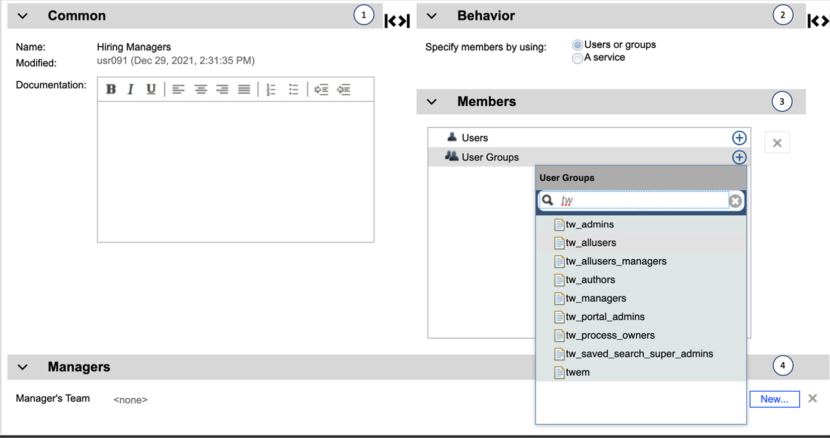
Figure 7.17 – Selecting team membership
- Following the same steps, we will create three separate teams. Feel free to experiment with the different team make-up to explore the authorization model:

Figure 7.18 – Completed team definitions
- Now, with the teams defined, we will assign them individually to the different swimlanes. We can do that by selecting the swimlane, and in the General section, select the team in the Default lane team setting:

Figure 7.19 – Updating team assignment
At this point, we have defined the process diagram and corresponding team definitions. However, how would the hiring managers specify which position they are making a request for? To do that, we need to first create a data model.
Defining data models
Let us design a simple data model for our tutorial. In workflow automation, we use the term business object (BO) to describe the data models within a process. The position request is represented by the PositionRequest BO, and it contains the following:
- reqID: This is a unique request ID.
- requestor: This is the name of the requestor.
- position: This is the position being requested. The position is defined by the Position BO.
- gmApproval: This tells us whether the GM has approved the request.
- gmComments: This tells us whether there are any comments that the GM has as part of the review.
In our tutorial, we have four BOs, as shown in Figure 7.20:
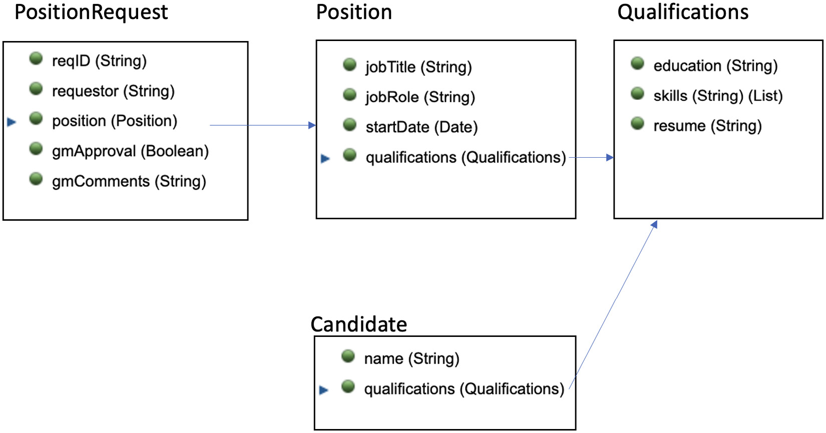
Figure 7.20 – Business objects for Hiring Process
Now, to define this in the workflow designer, in the Data section of the left navigation panel, we will select the New | Business Object options:

Figure 7.21 – Creating a new BO
A New Business Object dialog will pop up, and within it, specify PositionRequest as the name of the new Business Object:

Figure 7.22 – Creating a new Business Object “PositionRequest”
We will then be directed to the BO definition screen. To define the content of a BO, we’ll follow a simple three-step process:
- Press + to add a new parameter.
- Change the name from Untitled to match the name of the parameter.
- Press Select to pick an existing BO as the type, or New to define a new type. For example, since Position is a new BO, we can define it as part of defining the PositionRequest BO. Alternatively, we can use a bottom-up approach by first defining the Qualification BO, followed by the Position BO, then finally the PositionRequest BO.

Figure 7.23 – Business object details for PositionRequest
By following the preceding steps, we can define all four BOs. Here is the final definition of the PositionRequest BO:

Figure 7.24 – Final definition for PositionRequest
With all the BOs defined, we will need to update the process definition to indicate how the data will be used. We can do that by first updating the Variables section of the Request New Position process flow. Select the Process section and select the Request New Position process. Once we are there, go to the Variables section.
In the Variables section, we can specify the Input, Output, and Private variables of the process:
- Input variables are like input parameters to a Java function.
- Output variables are like the return value of a Java function (except in this case, we can have multiple output values).
- Private variables are variables that exist only when the process is running.
Input and Output variables are typically used as an interface for a subprocess. For this tutorial, we will be defining four private variables (reqID, requestor, request, and candidates).
We will follow a four-step process to define a variable, as shown in Figure 7.25:
- Press + to add a new variable.
- Rename the variable to match the name.
- Select the corresponding Business Object or Simple Type (for example, String or Number) as the variable type.
- Specify how the variable should be initialized. It is always a good practice to initialize your variable, or you might get a runtime exception when trying to access the data.

Figure 7.25 – Initializing variables for Request New Position process
In our case, we want to initialize the default reqID value to the same as the process instance ID. The process instance ID is guaranteed to be unique within a given workflow server environment, but it is not a global unique ID. If that is needed, it is best to generate a UUID. For now, we can initialize reqID to tw.system.process.instanceId.
For requestor, we will initialize it with the name of the person that started this process:
tw.system.user.fullName
The tw.system variable contains a set of system predefined values.
For the request and candidates variables, we will just use the system to generate the default initialization code for us by selecting the Has default checkbox:

Figure 7.26 – Setting default for complex variable
With all four variables defined in the process, they can now be used by the different tasks and gateways within the process.
To do that, flip to the Definition section and follow these steps:
- Select the Submit New Position Request user task.
- Select the Data Mapping tab in the properties view.
- In the Input Mapping section, add reqID and requestor.
- In the Output Mapping section, add request:

Figure 7.27 – Assigning inputs and outputs to Submit New Position Request activity
- Following the same approach, assign the Input Mapping and Output Mapping for Review New Request and Find Candidates:
|
Activity |
Inputs |
Outputs |
|
Review New Request |
request |
request |
|
Find Candidates |
request |
candidates |
Table 7.1 – Inputs and outputs for Review New Request and Find Candidates
- In the next step, we want to update the branch condition of the GM approved? gateway to route the process to Find Candidates when the approval is granted, or to End when the approval is denied. To do that, we select the gateway and specify in the Decisions section the correct condition to test. In this case, if gmApproval is not true, go to End:

Figure 7.28 – Gateway configuration for GM approved?
- To test the process, we can press play (1) again to run it:
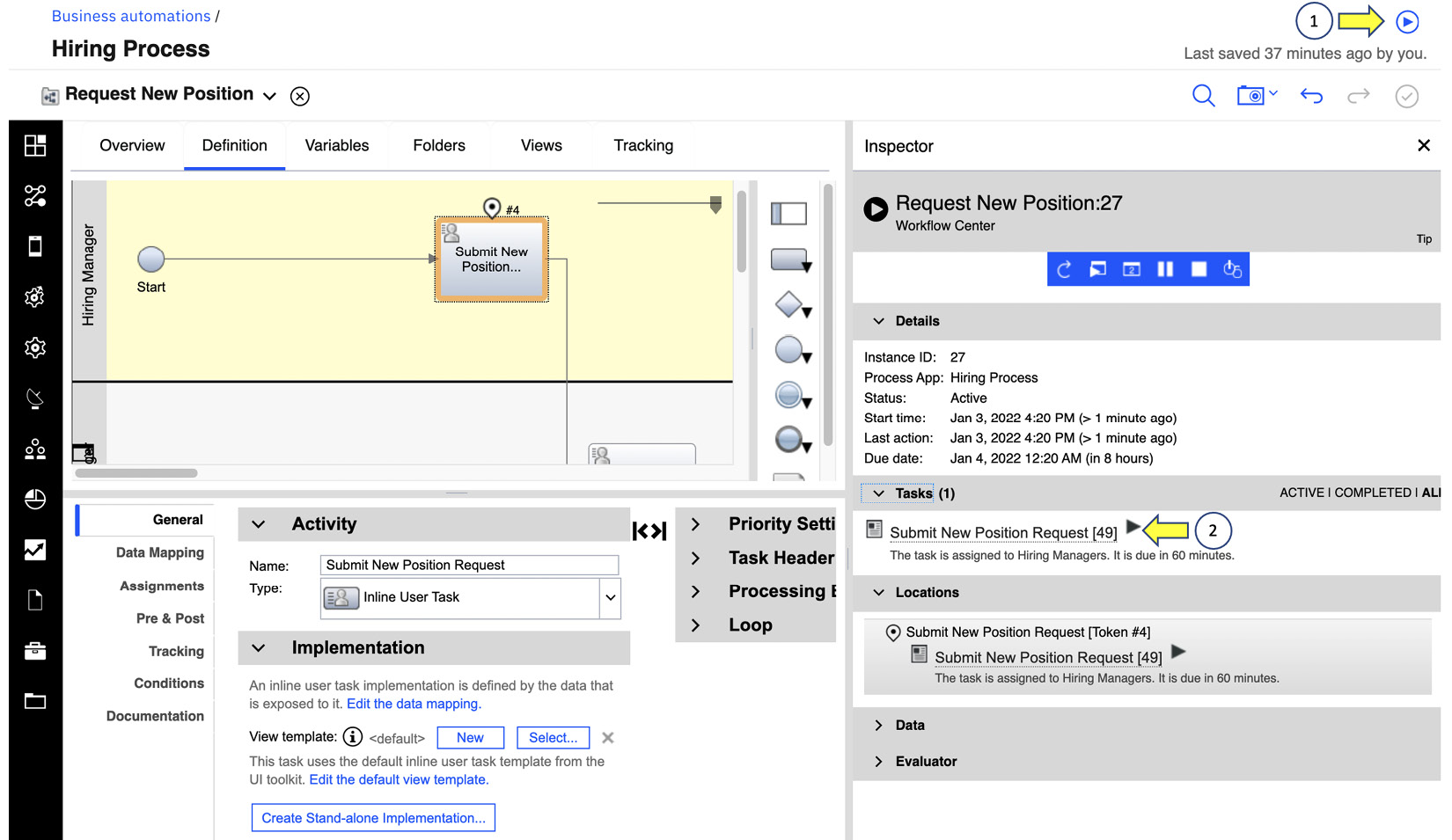
Figure 7.29 – Testing out the new updated process with Inspector
- Because we are still using Inline User Task, we do not have to worry about any user interfaces for the task workers as those will be generated for us from the data mapping. To launch the task, press the play icon right next to the active task (2):
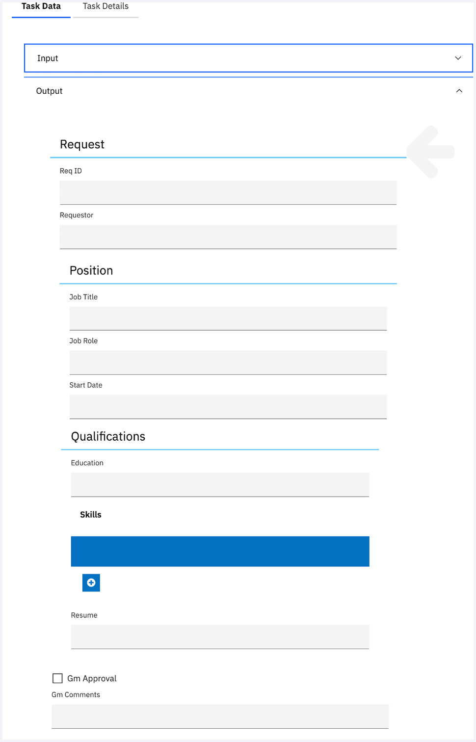
Figure 7.30 – Generated UI based on inputs and outputs
So far, we have covered the basics of building workflow automation:
- We use BPMN notation to create a runnable process that can be used by three separate groups of people.
- We make use of the Inline User Task feature to generate a default user interface to speed up our development effort.
- We also define a basic data model to capture the request and to define conditional logic for review and further processing.
Building the Task UI
In the previous section, we used an Inline User Task to automatically generate the Task UI based on input and output data mapping. While that is a useful technique to speed up our development, it is also common for business users to demand a more customized experience when working on tasks. To achieve that, we can make use of the built-in UI designer to build a custom task with the Client-Side Human Service (CSHS) and reusable View capabilities. In this part of the tutorial, we will replace the generated UI of Submit New Position Request with a custom UI.
To create this custom UI, we will create two reusable views (QualificationView and PositionRequestView) and one CSHS (Submit New Position Request):

Figure 7.31 – Custom UI with Client-Side Human Service and views
Views are reusable UI widgets that can be combined to create a more complex UI. There are close to 100 out-of-the-box views available for reuse. This same technology is used in both workflow automation and business applications, and we will go into more detail in Chapter 11, Engaging Business Users with Business Applications.
We will create QualificationView by first selecting the User interface section and then New | View options:

Figure 7.32 – Creating new views
Afterward, we specify the view name, QualificationView, and accept all the defaults:
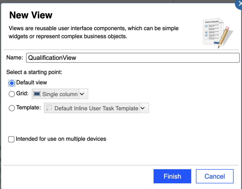
Figure 7.33 – Creating new views
Next, we go to the Variables tab of the view and add a new business data called qualifications with BO type Qualifications to it. This defines the data model that we will be using in the view:

Figure 7.34 – Assigning Variables in View
We then go to the Layout tab and start building the view using the WYSIWYG visual designer. To get started quickly, we can do the following:
- Switch to the Variable section in the palette.
- Select a field in Qualifications and drag it to the canvas. The designer will automatically select the best default for the field based on its data type.
- We can then adjust it in the Behavior section in the properties panel:

Figure 7.35 – View design for QualificationView
- By default, the label will be placed at the top of the input field. To get the preceding layout, we need to change the Label placement and Label width settings in the Appearance section of the Configuration tab:
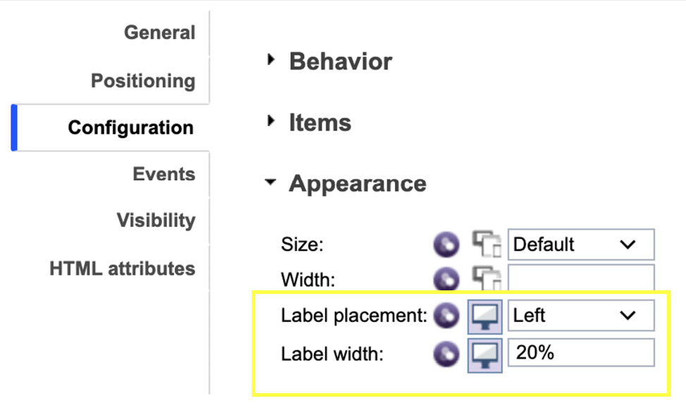
Figure 7.36 – Changing label placement in View design
- For Education Level, we want to change to use the view from Plain text to Single select so we can present a dropdown for the user:

Figure 7.37 – Changing to “Single select” in View design
- Now, to set the values to be used in the dropdown, we can set them as a list of static values or as the result of a service call. To set the value, we will go into the Configuration tab, select Items From Static List in the Item lookup mode settings, and type in the values directly in the Static list table:

Figure 7.38 – Providing a static list in Single select
As a result of the preceding settings, the Education Level field will become a dropdown with the following information:

Figure 7.39 – Education Level dropdown
- On the other hand, it sometimes would make sense to get the list of possible values from an external source, for example, external libraries or external REST services. In that case, we can make use of the other option, Items From Service:

Figure 7.40 – Items From Service
- In that case, we will create a new service flow (let us call it GetEducationType), where we will be using a script task to compose the possible choices as an array of NameValuePair:

Figure 7.41 – Creating a new service flow
- Here is the JavaScript snippet that we can use to return the list of possible choices:
tw.local.results = new tw.object.listOf.NameValuePair();
tw.local.results[0] = new tw.object.NameValuePair();
tw.local.results[0].name = "N/A";
tw.local.results[0].value = "N/A";
tw.local.results[1] = new tw.object.NameValuePair();
tw.local.results[1].name = "High School";
tw.local.results[1].value = "High School";
tw.local.results[2] = new tw.object.NameValuePair();
tw.local.results[2].name = "Bachelor";
tw.local.results[2].value = "Bachelor";
tw.local.results[3] = new tw.object.NameValuePair();
tw.local.results[3].name = "Master";
tw.local.results[3].value = "Master";
tw.local.results[4] = new tw.object.NameValuePair();
tw.local.results[4].name = "Ph.D.";
tw.local.results[4].value = "Ph.D.";
The code illustrates how we can make use of a service flow to provide information at runtime.
- By following a similar approach, we can complete PositiveRequestView, which can make use of QualificationView:
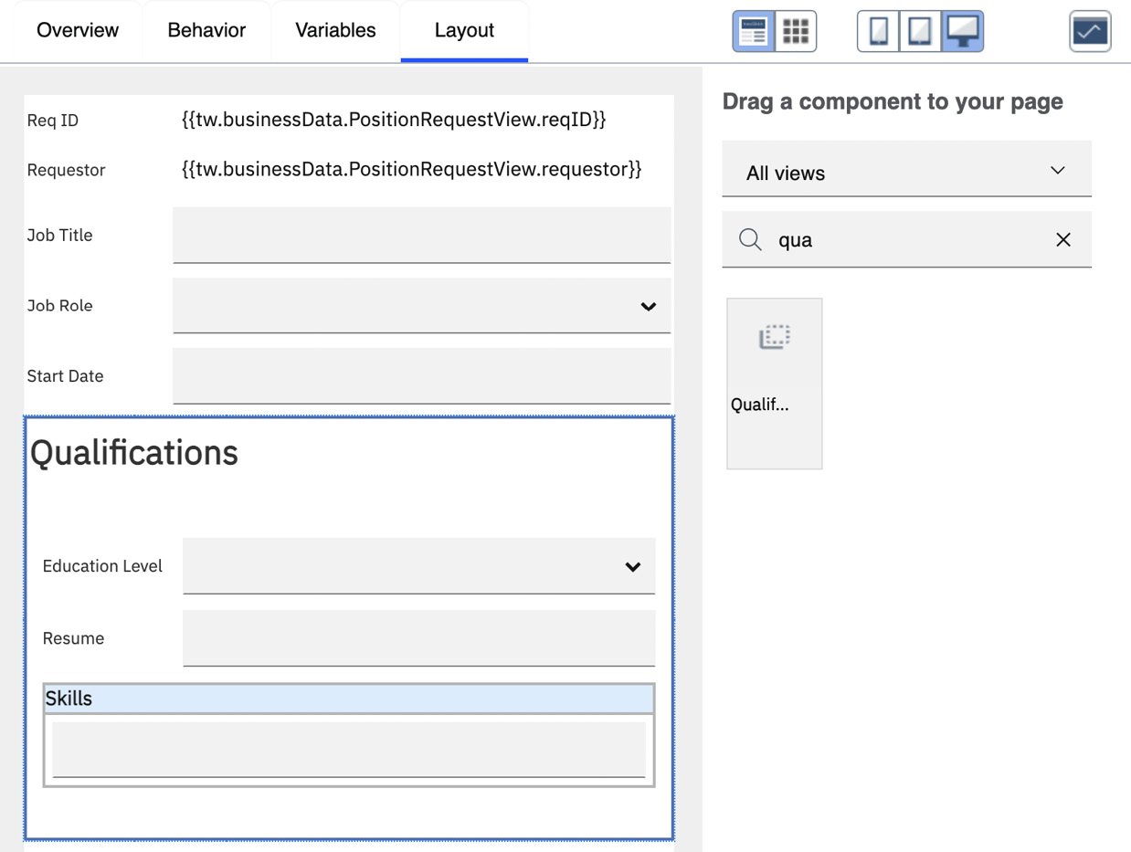
Figure 7.42 – Final PositionRequestView
- Once that’s done, the next step is to replace the original Inline User Task for SubmitPositionRequest with a custom user task. We can do that by selecting the Submit New Position Request activity in the process diagram and changing the Activity type from Inline User Task to User Task:

Figure 7.43 – Changing from “Inline User Task” to “User Task”
- The designer will then prompt us to create a new CSHS. A CSHS is a service flow that will be running on the client, and in our case, within the web browser of the task workers. This allows us to provide better responses to the task workers by delegating part of the work to the browser, thus reducing the workload on the workflow server.

Figure 7.44 – Creating a new CSHS
- In the new Submit New Position Request CSHS, we will select the same inputs and outputs as the original Inline User Task:

Figure 7.45 – Selecting the Input and Output for CSHS
This will create a simple CSHS with a single coach. A coach is like a view, except it represents the entire user interface that a task worker will see, as opposed to being just a reusable UI widget with the view. In our case, we will directly use PositionRequestView, and bind the inputs to reqID and requestor variables, and the outputs to request variables:
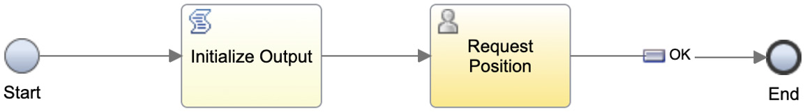
Figure 7.46 – Page flow for Request Position CSHS
- One thing to note is neither input nor output variables are initialized by default, which means they will have no values. For inputs, we can initialize them as part of the input mapping for the user task. For outputs, we typically will want to initialize them before calling the coach. In our case, we will use a script task (Initialize Output) to first create the output variable request.
We now have created a simple User Task UI with a custom CSHS implementation. If we are to go back to the process diagram and rerun the process, you will now have a new UI replacing the original generated UI:

Figure 7.47 – Submit New Position Request Task UI
In IBM BAW, we provide a very powerful user interface builder. There is a lot more that can be done by building a custom responsive task UI. To learn more, we can refer to the IBM Redbook, Deliver Modern UI for IBM BPM with the Coach Framework and Other Approaches (http://www.redbooks.ibm.com/abstracts/sg248355.html).
Integration with external services
As mentioned briefly before, we can use a service flow to call an external service to retrieve and store information gathered from the user interface. A typical use case is to store information in some external system of record (SOR). It is a good practice to not use the workflow automation itself as a system of record because of the following:
- The lifetime of your system of records is typically different from the life cycle of the workflow processes. For example, the retention period of a medical record might be 30 years, but we do not expect the same workflow system to be running for 30 years.
- There might also be multiple automation (workflow, robots, decisions, and apps) accessing the same information; as such, it is better to maintain your SOR in secure storage outside of the workflow system.
In our case, we will use an external data store to save the position request. For the sake of simplicity in this tutorial, we are going to use a simple PositionRequest service that is created using Loopback4.
To use the PositionRequest service, we must first import its service interface into the workflow project. We can do that by choosing the New | External Service options in the left navigation panel, Service. Once we are there, we will select the REST service from URL option and specify the URL where the service is being hosted:

Figure 7.48 – Creating new external service
By going through the rest of the dialog (accepting all defaults), we now have a new external service called PositionRequestStore with a set of operations matching those that are created by the Loopback4 implementation:
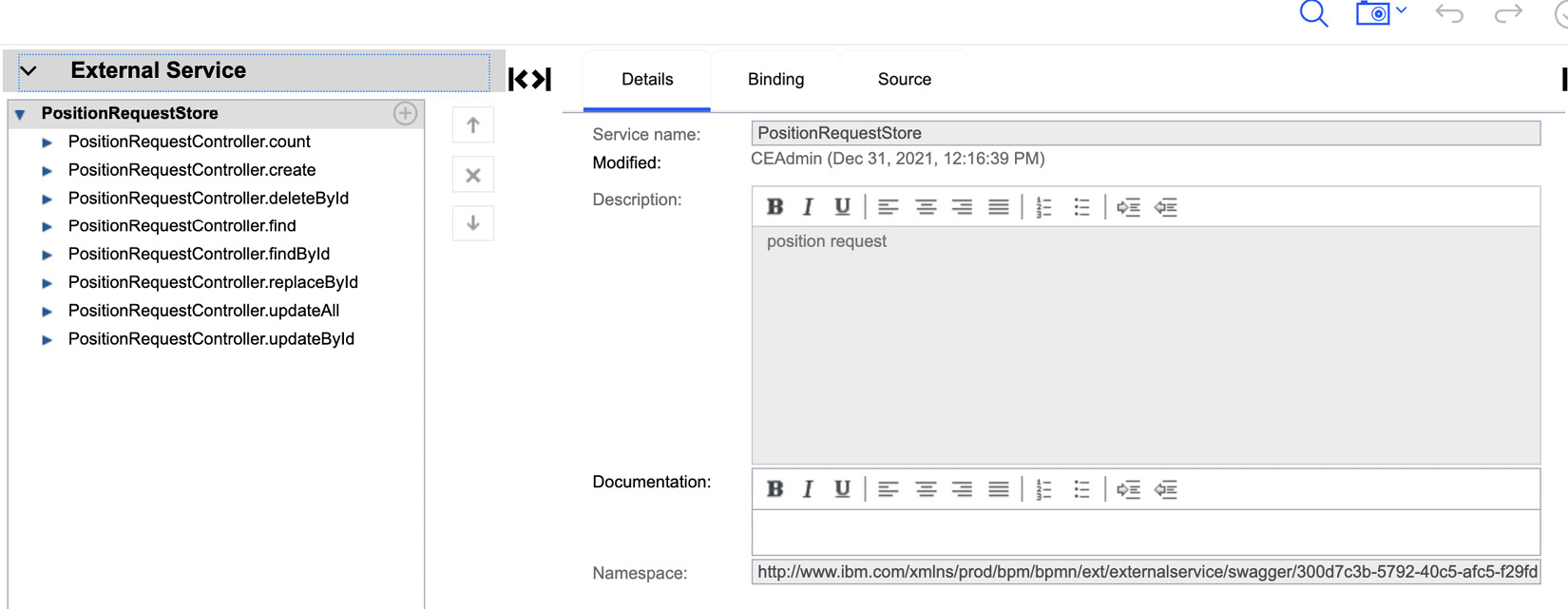
Figure 7.49 – PositionRequestStore External Service
In our case, we will create a service flow (PositionRequestCreate) that will call the PositionRequestController.create operation from the PositionRequest service:

Figure 7.50 – PostionRequestCreate service flow
The inputs and outputs of the new service flow are shown in Table 7.2:
|
Inputs |
Outputs |
|
request (type: PositionRequest) |
Success (type: Boolean) |
Table 7.2 – Inputs and outputs for the PositionRequestCreate service flow
In Figure 7.50, we also make use of an Error Event (![]() ) to redirect the logic to another script task to handle the failure should there be any error in the creation of the position request record. In this case, we will set the output variable (Success) of the service flow to false to indicate the call to the external service has failed.
) to redirect the logic to another script task to handle the failure should there be any error in the creation of the position request record. In this case, we will set the output variable (Success) of the service flow to false to indicate the call to the external service has failed.
Once the service flow is created, we can use it inside the Submit New Position Request CSHS by changing the CSHS to call the service flow once the user presses the OK button. We will also test the result of the save; if it fails, we will re-route the UI flow back to the coach and the user can resubmit the request at another time:

Figure 7.51 – Updated page flow to handle an exception
The preceding flow will stop the workflow from moving forward unless the request is saved successfully to the system of record.
Working with users
Now that we have a runnable workflow, how can we make this workflow available to be used by others? To do that, we need to first make this workflow solution exposed to other users by assigning the team that can start the process:
- To do that, we will go to the Overview tab of the Request New Position process and change the team assignment for the Expose to start setting to Hiring Managers:

Figure 7.52 – Exposing teams to start a workflow
Another important setting is Instance owners. This is where we can specify who can manage the life cycle of all instances of this process. In our case, we will assign that to the Human Resources team.
- Now for actual hiring managers to be able to launch this, they will first need to log in to IBM Workplace where they can see the list of available workflows they can use. IBM Workplace is the built-in user portal for users to both launch the workflow and work with their tasks.
- Once the hiring managers log into Workplace, they will see a simple dashboard with some basic statistics of the tasks assigned to them. At the start, there will not be any tasks as we have no workflow started yet:

Figure 7.53 – IBM Workplace
- To start a workflow, they can click on Start workflow and they will be taken to the Start workflow dialog where they can select the workflow to launch:

Figure 7.54 – Starting a new workflow in IBM Workplace
- Once launched, the hiring manager can now submit the New Position Request by claiming the task using the Open task option:
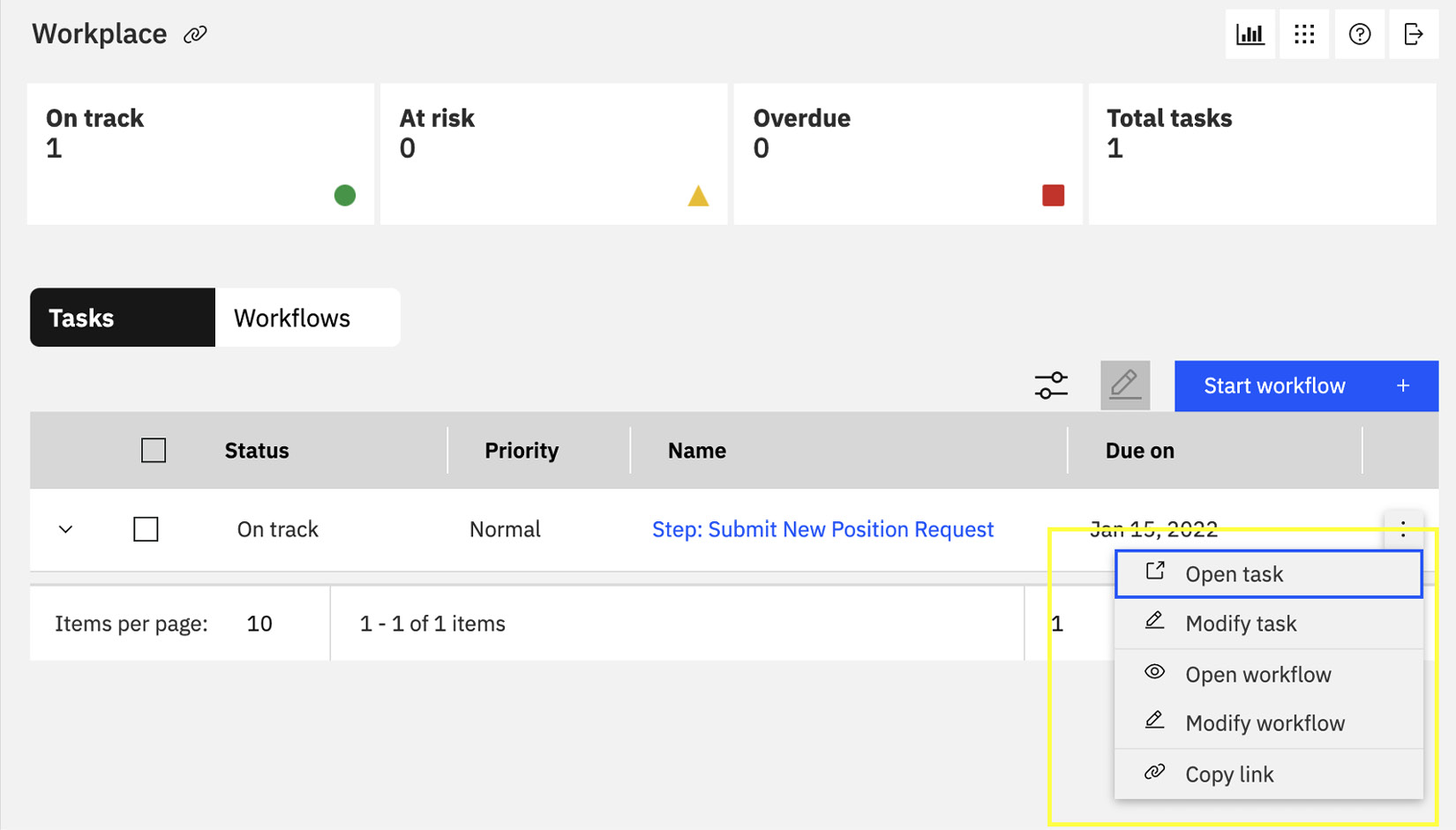
Figure 7.55 – Claiming task in IBM Workplace
Since IBM Workplace is built as a business application (see Chapter 11, Engaging Business Users with Business Applications), the automation developers can build similar applications to create custom solutions to manage workflows differently or to even embed your experience within other applications by making use of the available task management API.
Working together with robots
In the context of workflow automation, the purpose of RPA bots is to help human workers to simplify or automate their tasks. There are typically two approaches to incorporating the use of robots into a Workflow solution:
- Robots claiming tasks as humans: This is the least intrusive approach. In this approach, we will use the desktop automation capabilities of RPA bots to log into the IBM Workplace, launch a workflow, claim tasks, and work on them as if they are human workers. For auditability purposes and to better differentiate whether the work is performed by a bot or a human, it is better to establish a unique identity for the bots so we can find out later whether the tasks are performed by a bot or by a human. We can just add the bot identities as members of the teams.
- Calling robots as external services: IBM RPA provides a REST API to launch robots directly or using a bot process. In this approach, we will have to adjust the workflow definition to call the bot through the API. This approach is good if the plan is to integrate the workflow with a system that has no existing API. The drawback of this approach is we must modify the original workflow automation to account for some of the work that will be performed by a bot.
Packaging and deployment
The ability to create versions (we call them snapshots) and branches is not a new concept in development. In Business Automation Studio, we provide a built-in version control system so automation developers can be productive on the first day. To use that, we can go to the details page of the selected workflow automation to create new versions and branches:
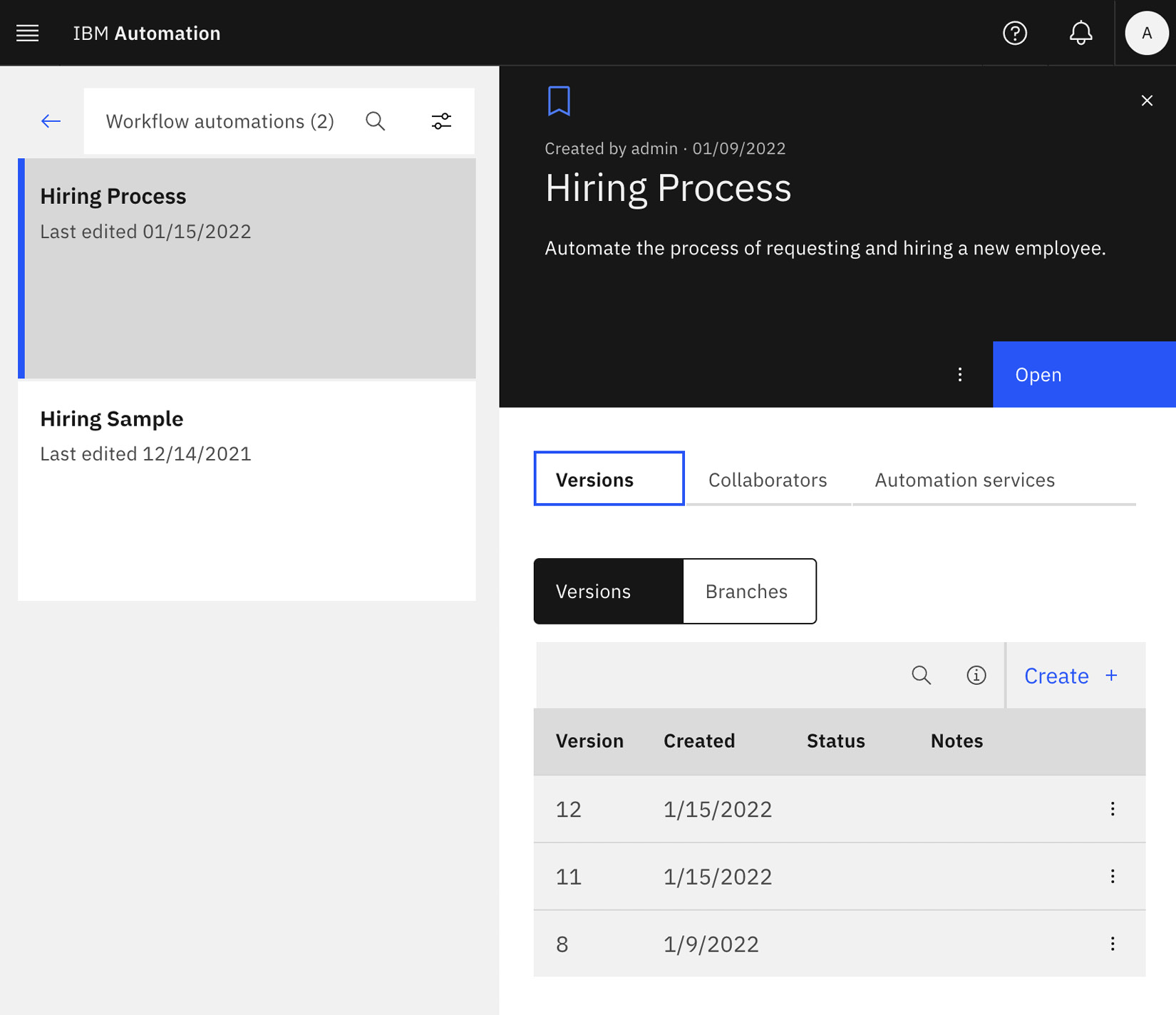
Figure 7.56 – Managing Versions and Branches for workflow automation
In addition, it is also possible to share the workflow automation project by exporting a particular version of it from the Versions tab:

Figure 7.57 – Exporting workflow automation package
Once you have the version exported, the automation developers can then share it with others or for deployment into other workflow systems.
Now let’s move on to the advanced topics of escalation, exception handling, and later, troubleshooting.
Escalation and exception handling
During a workflow, there can be two major exceptions kinds:
- System exceptions: Most of these deal with external system integration, whether it is to external services or to the actual workflow systems.
- Business exceptions: These are errors due to incorrect business assumptions or changes in business conditions.
Unless the exceptions are handled, it will usually result in the failure of the task at hand. To increase the robustness of your workflow automation, we provide several techniques to handle the exception by attaching an intermediate event to the activity:
- Error event for system or business exceptions: An error event allows the automation developer to redirect the logic flow if there is a system error during the execution of the task:

Figure 7.58 – Error event
- Timer event for escalation: A Timer event can be used to handle business escalation, for example, when a certain task is not completed within a certain time, the automation developers can trigger another workflow or direct the flow of the work differently:

Figure 7.59 – Timer event
It is not unusual for automation developers to initially focus on the success paths of workflow automation, but it is even more important for automation developers to consider both system errors and business errors that might arise during the execution of the workflow.
Administration and troubleshooting
Even with the best and most careful planning ahead of time, there are going to be situations where the business conditions are different or unexpected system or business exceptions happen during the execution of the workflow instance. In those situations, we will have to rely on the ability to manage the workflow instance outside of the development cycle. To do that, we will log into the Workflow Administration Console, and Workflow system administrators and instance owners will have visibility into the states of the currently running workflow instances.
Workflow instance owners and Workflow administrators can go into the runtime process inspector within the Process Admin Console to examine the current states of the workflow instances:

Figure 7.60 – Runtime process inspector
Inside the process inspector, we can provide different search conditions to search for active or completed workflow instances, and for each instance, we can find out their current state, the current set of tasks, and whether any of those have been claimed, completed, or failed. For failed tasks, the administrator can even restart them if they believe the failure conditions have been addressed already.
In addition, there are many things that workflow administrators can do, such as managing the operational health of the system by managing the various caches, cleaning up an orphaned or unwanted task, onboarding users, and creating teams (groups).
Summary
In this chapter, we provided a detailed walkthrough on building workflow automation with the Workflow designer using the BPMN notations. We also explained how automation developers can customize the task UI, and add integrations with external services or RPA bots.
We also provided a brief introduction on how to manage the process life cycle, how to handle exceptions and escalation with error and timer events respectively, and how to troubleshoot and manage the process instances with the runtime process inspector. While we only showed a simple Request and Approval process pattern, the same technique can be applied to implement more complicated workflow patterns.
In the next chapter, we will describe how to create reusable business logic with decision services.
Further reading
There are many other more advanced features such as process federation (allowing users to work on tasks from multiple workflow systems at the same time), or process instance migration (upgrading a running process instance to a new version). We will not be covering those topics here but more information can be found in IBM Business Automation Workflow Knowledge Center: https://www.ibm.com/docs/en/baw/20.x.