
Chapter 19. Raspberry Pi and Arduino
As novel as the Raspberry Pi is, you have to remember that the device is simply another Linux box. In other words, the Raspberry Pi, despite its tiny form factor, contains all of the trappings of a full-sized computer.
As nice as it is to have the input/output (I/O) capability of a full Linux machine, you still must deal with the unfortunate side-effect of system overhead. At times the Raspberry Pi cannot get out of its own way, so to speak, when you need it to perform certain tasks, especially those tasks that require precise timing and calibration.
Single-board microcontrollers like the Arduino are perfect for more direct applications that do not require intensive computing or graphical processing power. For instance, what if you wanted to design a wearable microcontroller that lights up a row of LEDs sewn into a leather jacket?
As it happens, the Arduino team in Italy made just such a microcontroller: the Lily Pad (http://is.gd/80MqhJ).
What if you wanted to design and control a robot composed almost entirely of paper? Again, the Arduino community has you covered with the PAPERduino (http://is.gd/5dSyJd).
As far as I am personally concerned, the Arduino is totally awesome. The good news is that you can integrate the Arduino with the Raspberry Pi in a number of different ways.
In this chapter I start by providing a bit of history on the Arduino platform. Next, I dig into the Arduino Uno, the reference Arduino model. I then show you how to get the Uno and Raspberry Pi talking to each other and exchanging data. Finally, I introduce an excellent Arduino clone that is about as easy to use with the Pi as any hardware I’ve ever seen.
Shall we get started?
Introducing the Arduino
Massimo Banzi, the cofounder of Arduino, said it best when he stated, “The Arduino philosophy is based on making designs rather than talking about them.”
The Arduino is a family of single-board microcontrollers that are completely open source. Yes, you heard me correctly: In contrast to the Raspberry Pi, which contains Broadcom-proprietary pieces and parts, the Arduino boards are completely open to the public.
This open source approach and Arduino’s Creative Commons-based licensing means that anybody in the world can design (and sell) their own Arduino clones. The only licensing aspect that the Arduino team feels strongly about is that clones must not contain the entire word “Arduino” in their names; this term is reserved for the official boards.
Speaking of boards, the Arduino team, which is based in Italy, manufactures and sells a large number of them. Check them out at the Arduino website at http://is.gd/6P6WSe; here are some of my favorite models:
![]() Arduino Uno (http://is.gd/SiSPg1): This is their most popular board and is ideal both for learning as well as for practical application.
Arduino Uno (http://is.gd/SiSPg1): This is their most popular board and is ideal both for learning as well as for practical application.
![]() Arduino Mega 2560 (http://is.gd/VPzRMr): This is a much bigger board intended for more comprehensive projects.
Arduino Mega 2560 (http://is.gd/VPzRMr): This is a much bigger board intended for more comprehensive projects.
![]() Arduino LilyPad (http://is.gd/80MqhJ): This is a cute, wearable microcontroller (see Figure 19.1).
Arduino LilyPad (http://is.gd/80MqhJ): This is a cute, wearable microcontroller (see Figure 19.1).

![]() Arduino Esplora (http://is.gd/YeZIIg): This board, which is also pictured in Figure 19.1, has lots of I/O possibilities and is focused squarely at game system designers.
Arduino Esplora (http://is.gd/YeZIIg): This board, which is also pictured in Figure 19.1, has lots of I/O possibilities and is focused squarely at game system designers.
Okay. Thus far we understand that Arduino represents a family of microcontroller boards and that their hardware is open source and anybody can download the schematics and build Arduino clones. Stepping back for a moment, what exactly is a “single-board microcontroller”?
A single-board microcontroller is a microcontroller that is soldered onto a single printed circuit board (PCB). Going further, a microcontroller, such as the 8-bit ATmel AVR used in the Uno, is an integrated circuit DIP chip that contains a processor core, a small amount of memory, and the capability to communicate with I/O peripherals that are located elsewhere on the PCB.
Note the decided absence of a video controller; microcontrollers have no built-in graphics capability, nor do they contain an operating system. This means you must program and control an Arduino from outside the Arduino, such as from a connected personal computer.
As a matter of fact, the mechanics of connecting an Arduino to the Raspberry Pi are exactly the same as those that govern connecting an Arduino to your Windows, OS X, or Linux-based PC. But I am getting a bit ahead of myself.
For me, the two coolest things about Arduino are (a) its analog inputs; and (b) shields.
The Arduino’s analog input pins mean that you can take analog measurements—for instance, temperature, volume, and so on...and convert them to digital values for processing. This means you can use the Arduino to interact with the real world, which is largely analog.
Note: Analog Versus Digital Signals
The reason quantities such as volume are analog is because their values change constantly over time over a wide range of values. By contrast, in the digital world there are only two values: 0 and 1, off and on, low and high, and so forth. When you convert an analog signal to digital, you try to approximate the wave-like pattern of analog to the up and down zig-zag of digital. The more data you feed into the translation, the more faithful the digital signal is of its analog counterpart (and vice versa).
A shield is an add-on board that extends the functionality of the Arduino. Typically, shields connect directly on top of the Arduino’s I/O pins...like a soldier holding a shield in front of him, actually.
Shields put the Arduino board on some serious steroids, let me tell you. It seems that either the Arduino team or a third party has developed an add-on shield for every conceivable computing (or noncomputing) purpose. For instance, take a look at this representative smattering of popular Arduino shields:
![]() Ethernet Shield (http://is.gd/PU2D0c): Gives your Arduino a wired Ethernet connection (see Figure 19.2).
Ethernet Shield (http://is.gd/PU2D0c): Gives your Arduino a wired Ethernet connection (see Figure 19.2).
![]() Wi-Fi Shield (http://is.gd/URoZZ9): Gives your Arduino connectivity to 802.1 b/g wireless networks.
Wi-Fi Shield (http://is.gd/URoZZ9): Gives your Arduino connectivity to 802.1 b/g wireless networks.
![]() GSM Shield (http://is.gd/JFB4NV): Gives your Arduino access to carrier networks (you also need a cellular service carrier’s SIM card).
GSM Shield (http://is.gd/JFB4NV): Gives your Arduino access to carrier networks (you also need a cellular service carrier’s SIM card).
![]() Relay Shield (http://is.gd/P63Pb4): Gives your Arduino the ability to control devices that use higher voltage circuits (perfect for home automation projects).
Relay Shield (http://is.gd/P63Pb4): Gives your Arduino the ability to control devices that use higher voltage circuits (perfect for home automation projects).
![]() Proto Shield (http://is.gd/nkmvNI): Gives you the ability to create your own shield from scratch—this is simply an unpopulated PCB with header connectivity to Arduino.
Proto Shield (http://is.gd/nkmvNI): Gives you the ability to create your own shield from scratch—this is simply an unpopulated PCB with header connectivity to Arduino.
The AlaMode that you learn how to use toward the end of this chapter is actually an Arduino shield.
Before we proceed into studying the Arduino Uno in great detail, let me return to the concept of the powerful Arduino community. You don’t have to have lots of money and manufacturing resources at hand to build your own Arduino.
As it happens, you can design and create an Arduino either from individual parts or by making use of several starter kits. Here, have a look:
![]() DIY Arduino (http://is.gd/70D1hc): This project is pretty novel, but is likely to require quite a bit of time to undertake.
DIY Arduino (http://is.gd/70D1hc): This project is pretty novel, but is likely to require quite a bit of time to undertake.
![]() Build an Arduino on a Breadboard (http://is.gd/AeVfiP): Believe it or not, it is feasible to build yourself an Arduino clone for all of $5 in parts.
Build an Arduino on a Breadboard (http://is.gd/AeVfiP): Believe it or not, it is feasible to build yourself an Arduino clone for all of $5 in parts.
![]() Adafruit Arduino Starter Pack (http://is.gd/7qFOJw): This kit includes an Uno R3 and myriad doo-dads for your experimenting and project prototyping pleasure.
Adafruit Arduino Starter Pack (http://is.gd/7qFOJw): This kit includes an Uno R3 and myriad doo-dads for your experimenting and project prototyping pleasure.
![]() Arduino Starter Kit (http://is.gd/NS4ff2): This project kit, which includes an Uno R3, is sold by the Arduino team directly.
Arduino Starter Kit (http://is.gd/NS4ff2): This project kit, which includes an Uno R3, is sold by the Arduino team directly.
Okay, then. Let’s drill into the Arduino Uno so we can begin to appreciate what the Arduino can do in Technicolor.
Digging into the Arduino Uno
The word Uno, as you probably already know, means one in Italian, and the Arduino Uno is called Uno to denote its association with the upcoming Arduino 1.0 PCB. According to the Arduino website, they are positioning the Uno and the Arduino 1.0 as the reference PCBs going forward.
As of this writing, the Arduino team has made three revisions to the Uno, with each subsequent revision adding features. Thus, I advise you to purchase an R3 board if you have anything to say about it.
You can easily tell which Uno revision you have by turning the board over and looking for the Rx label (where x is the revision number). For example, the Revision 3 board is labeled R3.
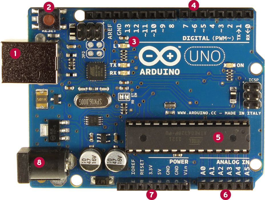
Now what’s on the front of the Uno? Figure 19.3 provides an annotated picture for you, but let me break the components down in a bit more detail:
2: Reset button
3: Pin #13 “blink” LED
4: Digital input/output pins
5: 7V-12V DC power
6: 3.3V and 5V power pins
7: Analog input pins
8: ATmega microcontroller
![]() ATmel ATmega328P AVR Microcontroller: The “brains” of the Arduino. The chip has a 16 MHz clock speed and 32KB of flash memory.
ATmel ATmega328P AVR Microcontroller: The “brains” of the Arduino. The chip has a 16 MHz clock speed and 32KB of flash memory.
![]() 14 digital output pins: Six of these pins support Pulse Width Modulation, or PWM. PWM enables you to take digital input and produce analog output. For instance, you can use PWM to dim LEDs instead of turning them on and off completely.
14 digital output pins: Six of these pins support Pulse Width Modulation, or PWM. PWM enables you to take digital input and produce analog output. For instance, you can use PWM to dim LEDs instead of turning them on and off completely.
![]() 6 analog inputs: This is how you get analog sensor data (think of volume, temperature, brightness, motion, and so on) into the Arduino.
6 analog inputs: This is how you get analog sensor data (think of volume, temperature, brightness, motion, and so on) into the Arduino.
![]() USB-to-serial chip: The ATmega16U2 enables the Uno’s USB bus to send and receive serial data.
USB-to-serial chip: The ATmega16U2 enables the Uno’s USB bus to send and receive serial data.
![]() Power supply: The Arduino itself operates at 5V, which means you need to be careful when you work with the 3.3V Raspberry Pi. The good news here is that the power output pins on the Uno support both voltages. Incidentally, the 3V3 pin supplies up to 50mA of power.
Power supply: The Arduino itself operates at 5V, which means you need to be careful when you work with the 3.3V Raspberry Pi. The good news here is that the power output pins on the Uno support both voltages. Incidentally, the 3V3 pin supplies up to 50mA of power.
![]() Reset: You can use this tactile button switch to reboot the Arduino.
Reset: You can use this tactile button switch to reboot the Arduino.
Power-wise, the Arduino Uno can accept power either through its dedicated power supply or through USB. If both are connected, the Uno defaults to using the dedicated 5V power supply.
Note: What’s a “Wall Wart”?
The Arduino Uno uses a standard 9V–12V, 250mA or more, AC-to-DC power supply with a 2.1mm plug. You can learn more about Uno-compatible power supplies by visiting Arduino Playground at http://is.gd/9WYgSK. The reason why these power supplies, which are ubiquitous in today’s portable electronics age, are called wall warts is because of the plug itself. As you doubtless know and much to your chagrin, the bulky transformer tends to block additional ports in your wall power receptacle or surge protector. Hence the disparaging term.
As I stated earlier, you can program the Arduino from an external computer. Sure, you could connect your Uno to your Windows or Mac computer, but in this book I focus squarely on the Raspberry Pi. Therefore, let’s now turn your attention to how you can link these two wondrous devices.
Connecting the Arduino and the Raspberry Pi
One of the fundamental lessons about physical computing that you should have picked up thus far is that any given task has several different valid methods of approach.
Some ways of solving a problem may be more efficient than others; yet others are more or less expensive to undertake. As long as you’re satisfied with the end result, there is no single, best way.
The reason I mention this is that there exist several methods for connecting the Arduino Uno to your Raspberry Pi. Again, you have some ways that are more or less efficient (and dangerous!) than others. Let me describe for you how some of these different types of connections work.
Connecting the Raspberry Pi GPIO Pins to the Arduino Serial Pins
This method requires the use of a voltage divider or logic level converter (buy one from Sparkfun at http://is.gd/Ws16r8) to manage the 3.3V/5V voltage difference between the two devices.
The advantage to this approach is that you free up the Raspberry Pi’s USB port for another use. The disadvantage is, as I just said, you must account for the voltage difference; doing this typically involves the introduction of a breadboard to host the logic level converter and jumper wires.
If you’re brave, you can study Oscar Liang’s tutorial on connecting the Raspberry Pi and Arduino Uno via serial GPIO, found at http://is.gd/I2QY7T.
Connecting the Raspberry Pi GPIO Pins to the Arduino I2C
This connection method does not require a logic level converter, as long as you configure the Pi as a master device and the Arduino as a slave device. Here are step-by-step instructions, again from Oscar Liang: http://is.gd/XBDg13.
The advantage to this method is that you free up both the USB bus as well as the serial pins on both devices. The disadvantage is that configuration is difficult. For instance, if you mess up the master/slave I2C communication between the devices you can easily fry your Pi with an overvoltage.
Connecting the Raspberry Pi to the Arduino via USB
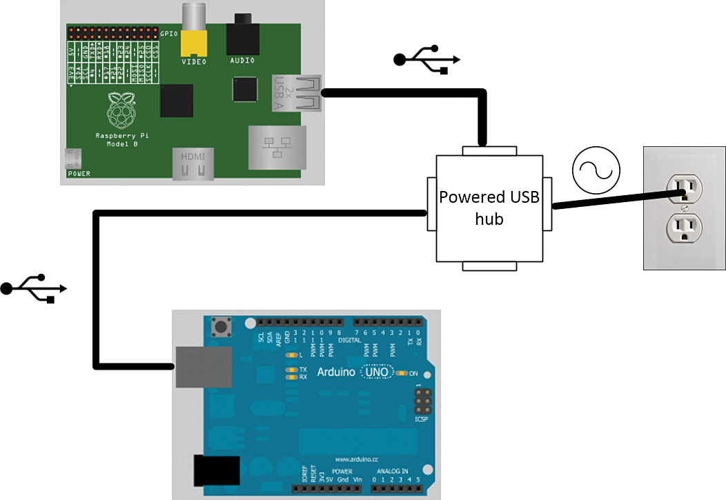
Ah yes...simplicity itself. This is the cleanest connection method insofar as you can literally plug the Arduino Uno into one of the Pi’s USB ports and access the Uno as a serial USB device.
The issue with this connection method, naturally, is one of power. If you have a wall wart power supply for your Arduino, you’re all set. Another solution is to plug your Uno into a powered USB hub that is in turn connected to the Pi’s USB port. That’s actually the method I use.
Connecting the Raspberry Pi to the Arduino via a Shield or Bridge Board
You now know what Arduino shields are, and it should come as no surprise to you that developers have taken it upon themselves to create Arduino-Raspberry Pi connection shields.
One of the most popular shields in this category is the Ponte (http://is.gd/nAvtEi). This shield is in a “currently experimental” state as of this writing, but it looks like a promising project.
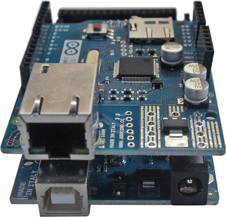
Imagine the possibilities of stacking a Ponte on top of a Raspberry Pi, an Arduino on top of the Ponte, and another Arduino shield stacked on top of the Arduino!
Connecting the Raspberry Pi to an Arduino Clone
The AlaMode shield and the Gertboard are both Arduino clones. Although the AlaMode is an Arduino clone that fits on top of the Raspberry Pi’s GPIO header like any traditional shield, the Gertboard’s ATmega microcontroller is just one of a number of widgets soldered into this multipurpose experimentation board. I show you how to use the AlaMode in this chapter, and you learn more about the Gertboard in Chapter 20, “Raspberry Pi and the Gertboard.”
Simply connecting the Arduino and the Raspberry Pi is only half the battle. You also have to take a look at the software side of the equation. This involves three discrete tasks:
![]() Configuring the Pi to recognize the Arduino
Configuring the Pi to recognize the Arduino
![]() Installing the Arduino IDE software
Installing the Arduino IDE software
![]() Developing sketches on the Pi and uploading them to the Arduino
Developing sketches on the Pi and uploading them to the Arduino
Note: All About Sketch
In Arduino nomenclature, a sketch is nothing more than a script file that constitutes your program source code. Sketch scripts, which will come up again, in the section “Task: Install and Configure Arduino IDE on the Raspberry Pi,” later in this chapter, are plain text files with an .ino extension that are readable in any text editor.
I believe the term sketch is meant to denote the programmer’s ability to quickly and easily sketch out his or her ideas in code and to be able to test the code immediately on a connected Arduino device.
Understanding the Arduino Development Workflow
You already know that the Arduino has no operating system of its own. I myself look at the Arduino as basically a dumb terminal. You can compose a set of instructions on a remote device, and then upload that script to the Arduino, where the script is stored in flash memory.
Immediately, the Arduino begins executing what’s in the script. Assuming the script is error-free and the Arduino does not suffer a hardware problem, the device will dutifully perform that work, theoretically forever.
Even if you press the hardware button to reset the Arduino, the currently loaded sketch continues to play. Any microcontroller worth its salt is all about reliably performing a single purpose.
The Arduino team created a piece of (surprise!) open source software called Arduino IDE (http://is.gd/UXSYgL) that you can use to program the Arduino. The software is free and is available for Windows, OS X, and Linux.
Specifically, Arduino IDE is a Java application and is based on the Processing programming language. Processing (http://is.gd/c6fUpT) is a C-type, object-oriented programming language that was created for those in the visual design community to teach the fundamentals of software development.
The tricky piece with installing the Arduino IDE on the Raspberry Pi is the Java Runtime Environment (JRE) requirement. Remember what I said earlier in the book about Java’s heaviness and the Pi’s tendency to choke on Java code? Yeah, that.
We’re going to rely on a splendid installation recipe that was developed by Kevin Osborn of the Bald Wisdom blog (http://is.gd/7RYaFm). Oh, Kevin is also on the AlaMode development team (http://is.gd/UvXxMF).
Task: Install and Configure Arduino IDE on the Raspberry Pi
1. First, make sure that your Pi’s firmware and system software are up-to-date. We originally covered this subject in Chapter 4, “Installing and Configuring an Operating System.”
2. Install the Arduino IDE; this step is simplicity itself:
sudo apt-get install -y arduino
3. Had Kevin not created a shell script for us, you would have had a dozen or more tedious configuration steps to undertake to force the Raspberry Pi to recognize the Arduino as a serial device (recall that the Uno includes an ATmel USB-to-serial chip; the Raspberry Pi has no such onboard convenience on its end).
If you want to understand all of the steps involved anyway, simply open Kevin’s script in a text editor and study away!
wget https://github.com/wyolum/AlaMode/blob/master/bundles/AlaMode-setup.tar.
gz?raw=true -O AlaMode-setup.tar.gz
tar -xvzf AlaMode-setup.tar.gz
cd AlaMode-setup
4. Note the reference to AlaMode. Kevin wrote this script with a dual-purpose in mind; namely, to configure the Pi to communicate both with the official Arduino Uno as well as the third-party AlaMode shield. I get to the AlaMode later; for now, run the setup script:
sudo ./setup
5. Once setup completes, you can reboot the Pi, or you can simply run the following command to initialize the system:
sudo udevadm trigger
6. To start the Arduino IDE, you need to be in a graphical environment, so make sure you fire up LXDE.
7. You will find an Arduino IDE shortcut in the Programming folder in the LXDE programs launcher, or you can run the following simple command from LXTerminal:
arduino
After a few moments, you should see the Arduino IDE interface as shown in Figure 19.5.

1: Menu system. Here you can find all the Arduino IDE commands nested in categories.
2: Verify. Here you can validate the syntax of your sketch.
3: Upload. Here you can transfer the current sketch to the Arduino’s flash memory.
4: New, Open, and Save, respectively. These buttons represent typical file management commands.
5: Sketch area. This is where you compose your Arduino source code.
6: Status area. This is where you receive feedback from the Arduino IDE with regard to code validation, compilation, and transfer.
7: Device information. This verifies that the Uno is linked, and reveals the serial port to which the Uno is connected.
Note: What Programming Language Does the Arduino IDE Use?
It’s actually rather confusing to determine exactly what programming language you’re using when you write sketches using the Arduino IDE. According to the Arduino website, the Arduino IDE employs its own open source programming language called, reasonably enough, the Arduino programming language.
Syntactically and functionally, the Arduino programming language is a simplified version of C/C++ and actually uses the avr-gcc C compiler. While we are on the subject, you might want to check out Simon Monk’s on-the-money book Programming Arduino: Getting Started with Sketches (http://is.gd/tdnYTw) if you’re looking for guided, end-to-end instruction on using the Arduino programming language.
Before you load up and run your first sample sketch, let’s take a moment to ensure that Arduino IDE is properly configured. First, point your mouse to the menu bar and click Tools, Board and make sure that IDE is set to Arduino Uno.
Second, click Tools, Serial Port and ensure that IDE is set to /dev/ttyACM0. Incidentally, ACM stands for abstract control model and refers to the ability to transmit old school serial data over the newer-school USB bus.
Task: Running the “Blink” Sample Sketch
1. In Arduino IDE, click File, Examples, 1. Basics, Blink. This loads the sketch into the IDE (see Figure 19.6).
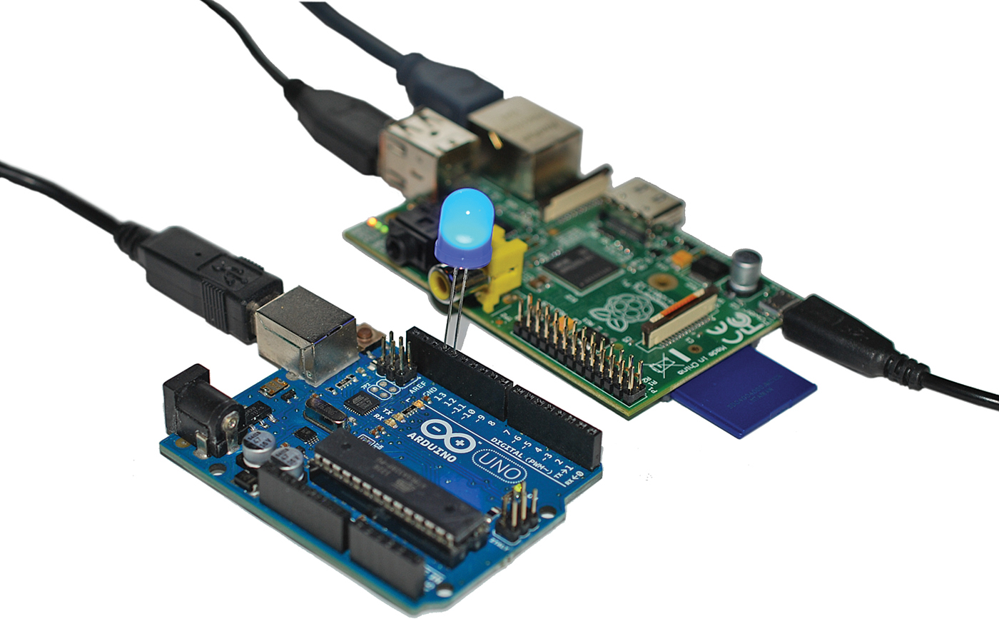
FIGURE 19.6 Testing out the Blink test sketch. Note that I’ve added an extra LED (you’ll learn how to do that, too).
2. Click the Upload button or click File, Upload Using Programmer to send the sketch to your Uno. The status bar reads Compiling sketch, Uploading, and then Done uploading when the transfer is complete.
Look at the surface-mounted LED marked L on the Uno board. Do you see it blinking once per second?
As shown here, you can put some more light on the subject by plugging a standalone LED into digital output pins 13 and ground. Before you do this, however, make sure you insert the longer leg (positive, or anode) into pin 13, and insert the LED’s shorter leg (negative, or cathode) into the GND pin.
Electrical current always flows from the anode to the cathode. The anode leg is made longer than the shorter simply as an easy way for us to determine which LED leg is which.
Because the surface-mount LED is also wired to pin 13, you should see both LEDs flash in unison.
You can learn a lot, exert control over the Arduino, as well as have some fun by analyzing the Blink sketch code line-by-line. Here’s the full code from the Blink test file; we’ll then analyze each major statement:
/*
Blink
Turns on an LED on for one second, then off for one second, repeatedly.
This example code is in the public domain.
*/
// Pin 13 has an LED connected on most Arduino boards.
// give it a name:
int led = 13;
// the setup routine runs once when you press reset:
void setup() {
// initialize the digital pin as an output.
pinMode(led, OUTPUT);
}
// the loop routine runs over and over again forever:
void loop() {
digitalWrite(led, HIGH); // turn the LED on (HIGH is the voltage level)
delay(1000); // wait for a second
digitalWrite(led, LOW); // turn the LED off by making the voltage LOW
delay(1000); // wait for a second
}
First of all, notice that the sketch includes two functions, setup() and loop(). The setup() procedure initializes a particular digital pin as a signal output.
How do we know we want pin 13? It’s right here:
int led = 13;
This statement creates a variable named led that can accept only integer (whole number) values. Furthermore, this line initializes the value of the led variable to 13. The 13 denotes pin #13 on the Arduino. You can find pin 13 by examining the digital pins on top of the Arduino Uno PCB. (Hint: pin 13 is located immediately to the right of the GND interface.)
pinMode(led, OUTPUT);
The pinMode() function accepts two arguments; first you pass in the variable, which is pin 13, and OUTPUT marks the pin for outgoing signal/current.
The loop() procedure does exactly what you think it does: it performs whatever actions you specify in the code block an infinite number of times. As previously stated, an Arduino runs its currently loaded sketch forever, unless and until you send it a new sketch to run. Singleness of purpose, remember?
digitalWrite(led, HIGH);
The digitalWrite() function puts the target LED in an on state (HIGH) or an off state (LOW). This is binary data we’re talking about.
delay(1000);
The delay function accepts an integer value in milliseconds. A value of 1000 means that the LED will stay on for 1 second.
Thus, the blink sketch does nothing more than cycles LED 13 on and off every second...forever. As an experiment, change the delay value from 1000 to 100 and reupload the sketch to your Uno. You should see the LED blink much faster.
Note: How to Clear Out Your Arduino
If you want to stop the Blink sketch, or if you want to clear any of the Arduino’s current actions, start a new, blank sketch file that contains the following lines:
void setup(){};
void loop(){};
Verify the sketch and then upload it to your Uno. I actually saved the sketch on my Pi and named it Clear for easy reuse.
Fading an LED
In this example with the Arduino Uno you test the use of analog output and PWM to gradually fade an LED.
Following is an inventory of what you need to have on hand to complete this experiment:
![]() Arduino Uno
Arduino Uno
![]() Breadboard
Breadboard
![]() 220 ohm resistor
220 ohm resistor
![]() LED
LED
You can study Figure 19.7 to learn the wiring schematic for this test.

With respect to that wiring diagram, please take into account the following notes:
![]() The (+) power rail is for incoming power.
The (+) power rail is for incoming power.
![]() The (-) power rail is for outgoing power (ground).
The (-) power rail is for outgoing power (ground).
![]() The Uno board in my schematic is from an earlier PCB release. As long as you choose a digital output pin labeled “PWM” or “~” you are good to go.
The Uno board in my schematic is from an earlier PCB release. As long as you choose a digital output pin labeled “PWM” or “~” you are good to go.
Using the AlaMode
Now that you have gotten to know an official Arduino board to a good degree of depth, let’s close out this chapter by looking briefly at one of the most popular Arduino clones, at least from the perspective of a Raspberry Pi enthusiast.
The AlaMode (http://is.gd/mm0Kfd) is an Arduino clone/shield that fits directly on top of the Raspberry Pi’s GPIO header pins. I show you an annotated close-up of the AlaMode in Figure 19.8.
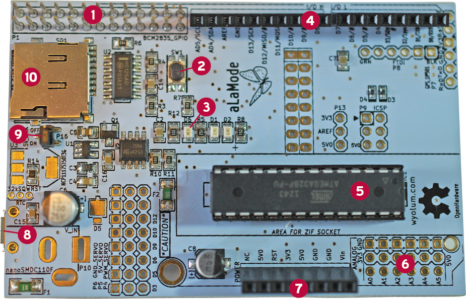
1: GPIO
2: Reset button
4: Digital I/O pins
5: Micro SD card slot
6: Power source jumper
7: Micro USB power input
8: ATmega microcontroller
9: Power pins
10: Analog input pins (unpopulated)
The AlaMode includes an impressive array of features besides its ease of connectivity to the Raspberry Pi:
![]() DS3234 Real Time Clock: Neither the Raspberry Pi nor the Arduino Uno has a battery-backed RTC. This is an excellent feature because you may want to run tasks that require precise timing and the Pi does not include a real-time clock “out of the box.”
DS3234 Real Time Clock: Neither the Raspberry Pi nor the Arduino Uno has a battery-backed RTC. This is an excellent feature because you may want to run tasks that require precise timing and the Pi does not include a real-time clock “out of the box.”
![]() Micro-SD Card Slot: You can perform data logging without having to access a network. Again, this is a tremendous convenience for certain projects.
Micro-SD Card Slot: You can perform data logging without having to access a network. Again, this is a tremendous convenience for certain projects.
![]() Power Flexibility: You can power the AlaMode directly from the Raspberry Pi through the GPIO, or you can plug in a wall wart or connect a traditionally DC battery.
Power Flexibility: You can power the AlaMode directly from the Raspberry Pi through the GPIO, or you can plug in a wall wart or connect a traditionally DC battery.
The AlaMode’s microprocessor is the same ATmega328P that you have on the Uno. AlaMode connects to the Pi as an I2C slave device and performs 5V-3.3V buffering. The AlaMode also includes a general-purpose blink LED on pin 13, just like the Arduino.
You can purchase the AlaMode through several channels; here are a couple:
![]() Maker Shed: http://is.gd/6eMMnC
Maker Shed: http://is.gd/6eMMnC
![]() Seeed Studio: http://is.gd/fFFDnQ
Seeed Studio: http://is.gd/fFFDnQ
Be sure to snag a copy of the user manual, too: http://is.gd/2bniUh.
Task: Getting the AlaMode Up and Running
![]() Make Video Podcast, Soldering Tutorial: http://is.gd/MALror
Make Video Podcast, Soldering Tutorial: http://is.gd/MALror
![]() Curious Inventor, How to Solder Correctly, and Why (video): http://is.gd/XIcaVx
Curious Inventor, How to Solder Correctly, and Why (video): http://is.gd/XIcaVx
![]() Electronix Express, Better Soldering: http://is.gd/9FYfXL
Electronix Express, Better Soldering: http://is.gd/9FYfXL
![]() Soldering is Easy Comic Book: http://is.gd/aNcuNQWith regard to the software configuration, as long as you’ve performed the steps given in the earlier procedure “Task: Install and Configure Arduino IDE on the Raspberry Pi,” you’ve completed most of the work.
Soldering is Easy Comic Book: http://is.gd/aNcuNQWith regard to the software configuration, as long as you’ve performed the steps given in the earlier procedure “Task: Install and Configure Arduino IDE on the Raspberry Pi,” you’ve completed most of the work.
1. Power off your Raspberry Pi.
2. If you want to power the RTC, insert a CR1632 battery into the associated clip on the AlaMode.
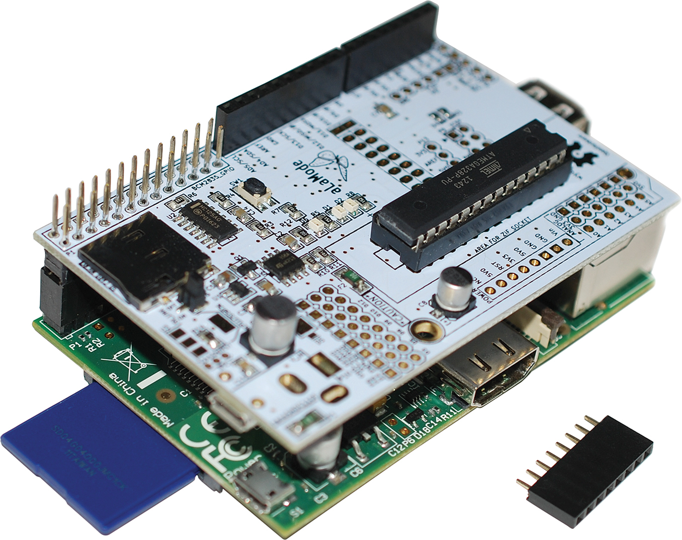
3. Gently push the AlaMode onto the Raspberry Pi’s GPIO pins. Make sure to line up the Pi GPIO with the AlaMode in the correct orientation; you can see the Pi-AlaMode sandwich (as well as some unsoldered headers) in Figure 19.9.
4. Now about power. You can configure the AlaMode to receive its power directly from the Pi’s GPIO header (assuming the Pi receives at least 1A of current on its own) or from a wall wart power supply.
In this tutorial, let’s power the AlaMode directly from the Pi. To do this, you must first set the 5V_Link jumper to ON as shown in Figure 19.10.

FIGURE 19.10 The AlaMode’s 5V_Link jumper is set by default to receive power through the Raspberry Pi GPIO.
The good news is that the AlaMode ships with the jumper set this way by default, so this is a verification step rather than a configuration step. By contrast, if you want to use an external power supply, you must move the jumper so that it covers the other pin, setting the switch to OFF.
Other than that, you can load up Arduino IDE on the Raspberry Pi and send sketches to the AlaMode in the very same way you did with the Arduino Uno.
5. In Arduino IDE, click Tools, Board and select AlaMode. Finally, click Tools, Serial Port and ensure that port /dev/ttyS0 is selected. Happy experimenting!