
Chapter 3. A Tour of Raspberry Pi Peripheral Devices
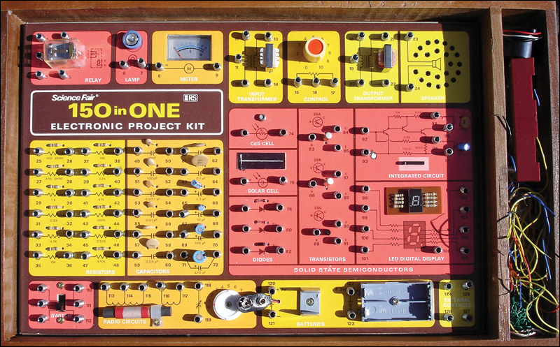
I got my start learning about electricity and electronics not through school but by horsing around with a Science Fair 160-in-1 electronics project kit my parents bought for me from Radio Shack for my tenth birthday.
As you can see in Figure 3.1, this wooden-framed kit enabled kids like me to prototype electrical circuits without having to solder any components together. The various “doo dads” on the kit’s circuit board kept me engaged and entertained for many, many hours.
Fast-forward to the twenty-first century—now we have the Raspberry Pi, a $35 personal computer the size of a credit card! In this chapter, I’d like to pique your curiosity by sharing with you the most popular peripheral devices—which is to say, electronic equipment that is connected to the Pi by means of a cable instead of soldered directly to the board—that exist in today’s marketplace.
If you want to really dig into physical computing and circuit building, you will indeed need to take an iron and braid in hand and learn to solder. I have you covered, though: You learn about all of the most popular starter kits and technician tools at the end of this chapter.
Let’s begin!
Circuit Prototyping Equipment
In electronics, prototyping refers to mocking up an idea in a way that the circuit can easily be rebuilt. To that end, the breadboard is by far one of the most useful tools you can have in your possession.
A breadboard is a plastic block that is perforated with small holes that are connected internally by tin, bronze, or nickel alloy spring clips. Take a look at Figure 3.2 as a reference while I explain how these devices work.

FIGURE 3.2 Anatomy and physiology of a breadboard. A terminal strip is labeled 1, the bridge is labeled 2, and a bus strip is labeled 3.
First of all, see the empty area that runs down the center line of the breadboard? This region is called the bridge. It’s a physical barrier that prevents current on one side from interacting with current on the other side. Thus, the breadboard is bilaterally symmetric, which is a fancy way of saying it consists of two mirror image halves that represent two separate circuits.
When you mount integrated circuit chips that use the dual inline package (DIP) format on a breadboard, be careful to align the opposing sets of pins on opposite sides of the bridge to prevent circuit overflow.
If you are wondering what a DIP looks like, whip out your Raspberry Pi board and look below the GPIO header: the voltage regulators labeled RG1, RG2, and RG3 are DIPs.
The horizontally numbered rows of perforations represent the breadboard’s terminal strips. Any wires that you connect in a single row share a single electrical circuit. Breadboards come in several different sizes, and each has its own number of terminal strips.
For instance, full-sized breadboards typically include 56 to 65 connector rows, while smaller breadboards normally have 30 rows.
Finally, there are the horizontally aligned perforations that line the outer edges of the breadboard. These are called bus strips, and they constitute “power rails” for your prototype circuits. One connector column represents supply voltage (positive), and the other represents ground (negative).
In sum, the breadboard is the perfect platform for prototyping electrical circuits because you don’t need to solder anything. Instead, you can simply “plug and play” with ICs, resistors, lead wires, buttons, and other components.
Of course, all of this background information on breadboarding suggests the question, “Why would I, a Raspberry Pi owner, want to prototype anything?”
Great question! Here’s the deal: If you want to use your Raspberry Pi to interact with the outside world, whether that interaction is controlling a robot, snapping pictures from 30,000 ft in the air, or creating a solar-powered weather station, you’ll need to learn how to use prototyping hardware such as breadboards, resistors, jumpers, and the like.
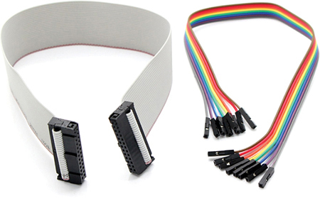
On the Raspberry Pi, the 26 General Purpose Input/Output (GPIO) pins are used to “break out” the Pi onto a breadboard. You can do this by using two different types of cable:
![]() Ribbon cable: This flat cable connects to all the GPIO pins simultaneously
Ribbon cable: This flat cable connects to all the GPIO pins simultaneously
![]() Jumper wire: This wire connects a single GPIO pin to a terminal on the breadboard. Jumper wires are also called straps, and you’ll use several of them when we use the Gertboard expansion board in Chapter 20, “Raspberry Pi and the Gertboard.”
Jumper wire: This wire connects a single GPIO pin to a terminal on the breadboard. Jumper wires are also called straps, and you’ll use several of them when we use the Gertboard expansion board in Chapter 20, “Raspberry Pi and the Gertboard.”
A ribbon cable and jumper wires are shown in Figure 3.3.
Breakout boards provide an excellent and convenient way to connect your Raspberry Pi to a solderless breadboard. I recommend the Pi Cobbler kit, sold by Adafruit Industries (http://is.gd/b4LlQ7).
As you can see in Figure 3.4, you mount the Pi Cobbler board across the breadboard bridge (do you like my alliteration?). The ribbon cable connects from the Cobbler to the Pi’s GPIO header on the other side of the connection.

Once you’ve broken out your Pi to the breadboard, you have the proverbial world available to you. In point of fact, the latter part of this book walks you through some real-world projects that take advantage of the Raspberry Pi-breadboard connection.
Single-Board Microcontrollers
Recall from our initial discussion in Chapter 1, “What is the Raspberry Pi?” that a microcontroller is a PCB that is designed primarily for a small number of time-dependent tasks.
The big benefit of integrating your Raspberry Pi with a microcontroller is that you can connect to an almost endless number of analog and digital sensors. This means you can write programs that detect and take action on the following and more:
![]() Light
Light
![]() Moisture
Moisture
![]() Sound/Volume
Sound/Volume
![]() Contact
Contact
![]() Motion
Motion
The Arduino platform (www.arduino.cc) is a suite of electronics prototyping PCBs that are dearly loved by artists, designers, inventors, and hobbyists for their ease of use and flexibility.
Hobbyists have developed some pretty cool technology by using Arduino microcontrollers: motion sensors, home automation systems, MIDI controllers, radon detectors...the list of project ideas is seemingly endless.
The Raspberry Pi–Arduino heavenly match is discussed in Chapter 19, “Raspberry Pi and Arduino.” For now, however, let’s go over the basic “gotchas” of this electronic marriage:
![]() Connection options: To connect your Raspberry Pi to an Arduino board, you can either use a USB cable or a I2C (pronounced eye-squared-see) serial link. You can see the Pi and Arduino UNO lined up side-by-side in Figure 3.5.
Connection options: To connect your Raspberry Pi to an Arduino board, you can either use a USB cable or a I2C (pronounced eye-squared-see) serial link. You can see the Pi and Arduino UNO lined up side-by-side in Figure 3.5.
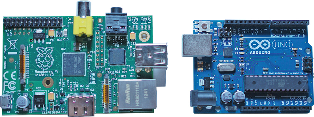
FIGURE 3.5 You can connect an Arduino board directly to the Raspberry Pi by using USB, serial, or GPIO connections.
![]() Voltage differences: We already know from Chapter 2, “Hardware Components Quick Start,” that the Raspberry Pi accepts 5V inbound power but operates at 3.3V internally. By contrast, the Arduino operates externally and internally at 5V. Consequently, when joining Pi with Arduino you need to invest in an external voltage regulation solution to avoid burning up your Pi.
Voltage differences: We already know from Chapter 2, “Hardware Components Quick Start,” that the Raspberry Pi accepts 5V inbound power but operates at 3.3V internally. By contrast, the Arduino operates externally and internally at 5V. Consequently, when joining Pi with Arduino you need to invest in an external voltage regulation solution to avoid burning up your Pi.
![]() Administration: Recall that the lack of an operating system is one of the defining characteristics of a single-board microcontroller. Therefore, in an Arduino/Raspberry Pi nexus, all your Arduino programming happens on the Pi, and you upload your Arduino “sketches” to that hardware over the serial or USB connection.
Administration: Recall that the lack of an operating system is one of the defining characteristics of a single-board microcontroller. Therefore, in an Arduino/Raspberry Pi nexus, all your Arduino programming happens on the Pi, and you upload your Arduino “sketches” to that hardware over the serial or USB connection.
Note: But Wait, There’s More!
Perhaps the most elegant way to connect your Arduino board to your Raspberry Pi is to purchase the Alamode shield (http://is.gd/4H3aWv). The Alamode is an Arduino device that connects directly to the Pi’s GPIO header and provides a real-time clock, seamless connectivity to the Arduino microcontroller application programming interface (API), and voltage regulation to the Pi. It’s a great deal!
Please note that despite its overwhelming popularity, the Arduino is not the only single-board microcontroller game in town. Here’s a quick list of single-board microcontroller vendors that you might find useful:
![]() Texas Instruments MSP430 LaunchPad (http://is.gd/xbAjcO)
Texas Instruments MSP430 LaunchPad (http://is.gd/xbAjcO)
![]() Teensy (http://is.gd/rlEIxy)
Teensy (http://is.gd/rlEIxy)
![]() STM32 (http://is.gd/TscRtp)
STM32 (http://is.gd/TscRtp)
![]() Pinguino (http://is.gd/rdEpF5)
Pinguino (http://is.gd/rdEpF5)
The Gertboard
What the heck is a Gertboard, you ask? Gert van Loo is a computer electronics engineer who was the chief architect of the Raspberry Pi PCB. Gert designed the Gertboard as a Raspberry Pi expansion board, or daughterboard, that makes it easy to detect and respond to physical (analog) events such as voltage changes, motor state changes, and the like.
A daughterboard is a printed circuit board that is intended to extend the functionality of mainboard. In this context, the Raspberry Pi is the mainboard, and the Gertboard is the daughterboard. In full-sized PCs, daughterboards, which are also called mezzanine boards or piggyback boards, are often used to enable expansion cards to mount on their side, parallel to the motherboard, in the name of making the PC’s form factor as slim as possible. Question: Do you think the world needs a brotherboard? How about a second-cousin-twice-removedboard?
The Gertboard is awesome because it saves you the work of building circuits with a breadboard. The Gertboard PCB is literally covered with useful electrical components like the following:
![]() Tactile buttons
Tactile buttons
![]() LEDs
LEDs
![]() Motor controllers
Motor controllers
![]() Digital-to-analog and analog-to-digital converters
Digital-to-analog and analog-to-digital converters
The Gertboard and the Pi connect together directly by means of (what else?) the Pi’s GPIO header. Figure 3.6 shows you a close-up of the amazing Gertboard.

Just wait—you get to use the Gertboard in Chapter 20.
Single-Board Computers
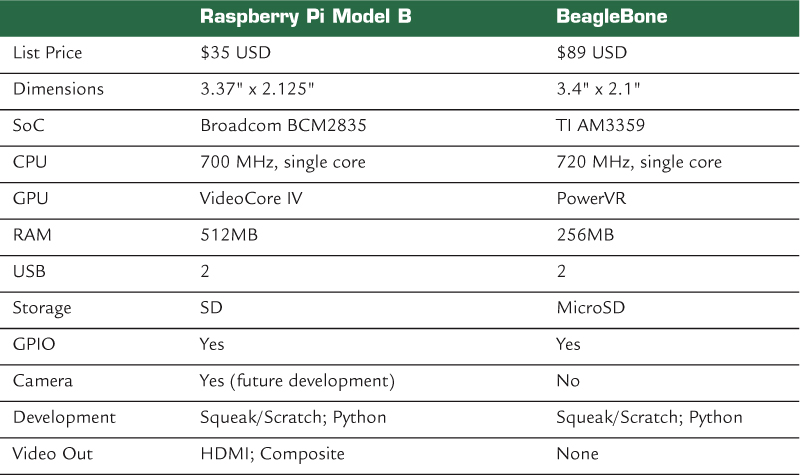
The BeagleBone (http://is.gd/A5m89F) is perhaps the Raspberry Pi’s chief competitor in the single-board computer market. The BeagleBone is, like the Raspberry Pi, an ARM-based, credit card-sized Linux computer.
The BeagleBone is actually the smaller sibling of the BeagleBoard. Both boards are manufactured by the legendary Texas Instruments (TI), which lends immediate credibility to the Beagle projects.
Serious gearheads prefer the BeagleBone because its ARM Cortex A8 processor (running at 720 MHz) supports the ARMv7 instruction set, as opposed to the ARMv6 set included with the Pi.
Because of its support for ARMv7, the BeagleBone’s benchmark performance is much better than that of the ARMv6-equipped Raspberry Pi. You also have a wider range of Linux distributions to choose from with ARMv7-compatible devices such as the ‘Bone.
The BeagleBone and the Raspberry Pi aren’t exactly “finger in glove” partners like the Arduino and Pi. Really, they are competitors in the same or highly similar market space. Table 3.1 compares and contrasts the technical specifications for both systems.
Here’s a noncomprehensive list of other single-board computer manufacturers:
![]() Cotton Candy (http://is.gd/quXmJu)
Cotton Candy (http://is.gd/quXmJu)
![]() CuBox (http://is.gd/B6hvsZ)
CuBox (http://is.gd/B6hvsZ)
![]() Gumstix (http://is.gd/29EJ4A)
Gumstix (http://is.gd/29EJ4A)
![]() PandaBoard (http://is.gd/5of9yx)
PandaBoard (http://is.gd/5of9yx)
“Why is it important that I understand the Raspberry Pi’s competition?” you might ask. In my estimation, it is important for you to know that there exist alternatives to the Raspberry Pi. You may find, for example, that the Pi is the best fit for the types of learning goals and projects that you have in mind. By contrast, you may also save yourself time, money, and frustration by concluding at the outset that you should consider an Arduino or a BeagleBone rather than a Pi.
Relevant Technician Tools
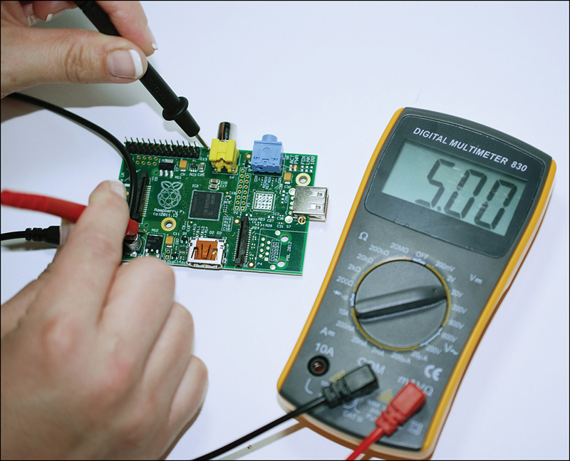
To perform all aspects of physical computing with your Raspberry Pi, you’ll need a few electrical tools. Chief among these is the digital multimeter, an instrument with which you can measure electrical current, voltage, and resistance.
For instance, you can run a quick verification of the Raspberry Pi’s 5V power supply voltage by using a multimeter and the TP1 and TP2 test points on the Model B board.
To locate the TP1 and TP2 test points, take a closer look at Figure 2.2. You’ll see TP1 located just above and to the right of the C2 capacitor and TP2 just to the left of the RCA video output (assuming you are looking at the PCB with the Raspberry Pi logo facing up).
Task: Check Raspberry Pi Voltage with a Multimeter
1. Turn on your multimeter and set the dial to a low voltage threshold (for instance, 20V is good). If you own an autoranging multimeter, you don’t need to worry about this step.
2. Disconnect all peripherals (including the SD card) from your Pi except for the Micro USB power supply cable.
3. Power up your Pi.
4. Place the hot (red) lead to the TP1 test point, and place the ground (black) lead to the TP2 test point. You want to connect the leads simultaneously.
5. Verify that the multimeter shows a net voltage of approximately 5V (see Figure 3.7).
You’ll also need a soldering iron, which is a tool you use to permanently join electrical components and to extend circuits.
The very idea of soldering intimidates some people, but the kernel idea at play is really quite simple. You heat up the soldering iron to 700 degrees Fahrenheit or so and then melt solder into a junction between two other conductive components. When the solder dries, you have a permanent connection that allows electrical current to flow between the soldered components.
In a nutshell, solder is a fusible metal alloy that, as a conductor, can transmit electricity.
For Raspberry Pi projects, I recommend you get an adjustable 30W pen-style soldering iron for maximum flexibility. You also should purchase a spool of 60/40 lead rosin-core solder with a 0.031-inch diameter. The 60/40 means that the solder consists of 60 percent tin and 40 percent lead.
To make your soldering experience as user-friendly as possible, you might also want to look into the following relevant soldering accessories:
![]() Solder sucker: This vacuum tool makes short work of removing melted solder particles.
Solder sucker: This vacuum tool makes short work of removing melted solder particles.
![]() Solder wick: This material, also called desoldering braid, is used in conjunction with the solder sucker to remove solder from your components.
Solder wick: This material, also called desoldering braid, is used in conjunction with the solder sucker to remove solder from your components.
![]() Soldering stand: We have only two hands, and if you are operating the iron with one hand and the solder wire with the other, then how the heck can you position your components to be soldered? Because using The Force isn’t an option (probably), a soldering stand makes this easy.
Soldering stand: We have only two hands, and if you are operating the iron with one hand and the solder wire with the other, then how the heck can you position your components to be soldered? Because using The Force isn’t an option (probably), a soldering stand makes this easy.
Raspberry Pi Starter Kits
With so many hardware options available to Raspberry Pi enthusiasts, figuring out where to start can seem overwhelming to even experienced tech junkies.
For the befuddled (among whose number I once counted myself a member), several third-party vendors assemble so-called Raspberry Pi starter kits that include everything you need to start building Raspberry Pi-based projects. Heck, most of the kits even include a Model B board! This section lists a few such kits.
The Adafruit Raspberry Pi Starter Pack (http://is.gd/cf3pIy) lists for $104.95. Besides the Model B, you also get the following components for your money:
![]() Adafruit clear acrylic Pi box
Adafruit clear acrylic Pi box
![]() 3′ long Micro USB cable
3′ long Micro USB cable
![]() 5V 1A power adapter
5V 1A power adapter
![]() USB TTL console cable
USB TTL console cable
![]() 4GB SD card
4GB SD card
![]() Assembled Adafruit Pi Cobbler kit with GPIO cable
Assembled Adafruit Pi Cobbler kit with GPIO cable
![]() USB microSD card reader
USB microSD card reader
![]() Large, full-size breadboard
Large, full-size breadboard
![]() Breadboarding wires
Breadboarding wires
![]() 10′ long Ethernet cable
10′ long Ethernet cable
![]() Embroidered Raspberry Pi badge
Embroidered Raspberry Pi badge
![]() 5 x 10K ohm resistors
5 x 10K ohm resistors
![]() 5 x 560 ohm resistors
5 x 560 ohm resistors
![]() 1 Red 10mm diffused LED
1 Red 10mm diffused LED
![]() 1 Green 10mm diffused LED
1 Green 10mm diffused LED
![]() 1 Blue 10mm diffused LED
1 Blue 10mm diffused LED
![]() 3 tactile pushbuttons
3 tactile pushbuttons
![]() Light-sensitive resistor photocell
Light-sensitive resistor photocell
![]() 1 x 1uF capacitor
1 x 1uF capacitor
The Maker Shed Raspberry Pi Starter Kit (http://is.gd/YIWK7Z) costs $129.99 and also includes a Model B board. In addition, the pack includes the following:
![]() Adafruit Pi Cobbler Breakout Kit
Adafruit Pi Cobbler Breakout Kit
![]() MAKE: Pi Enclosure
MAKE: Pi Enclosure
![]() 2-port USB wall charger (1A) and USB cable
2-port USB wall charger (1A) and USB cable
![]() 4GB Class 4 SDHC flash memory card
4GB Class 4 SDHC flash memory card
![]() Deluxe, full-sized breadboard
Deluxe, full-sized breadboard
![]() Mintronics Survival Pack with 60+ components, including voltage regulators, trimpots, LEDs, pushbuttons, battery snaps, capacitors, diodes, transistors, and resistors
Mintronics Survival Pack with 60+ components, including voltage regulators, trimpots, LEDs, pushbuttons, battery snaps, capacitors, diodes, transistors, and resistors
![]() HDMI high-speed cable, 1.5 feet
HDMI high-speed cable, 1.5 feet
![]() Deluxe breadboard jumper wires
Deluxe breadboard jumper wires
The previous two Raspberry Pi starter kits are decidedly weighted toward electronics experimentation. There are also vendors who will sell you kits that include the Pi as well as core peripherals.
For instance, consider the CanaKit Raspberry Pi Complete Starter Kit ($89.95, http://is.gd/HnsiOJ), which includes the following parts:
![]() Raspberry Pi Model B
Raspberry Pi Model B
![]() Clear case
Clear case
![]() Micro USB power supply
Micro USB power supply
![]() Preloaded 4GB SD card
Preloaded 4GB SD card
![]() HDMI cable
HDMI cable
MCM Electronics (http://is.gd/6cAfs3) offers several different Raspberry Pi kits. Their Raspberry Pi Enhanced Bundle lists for $79.99 and includes the following:
![]() Raspberry Pi Model B
Raspberry Pi Model B
![]() 5V 1A Micro USB power supply
5V 1A Micro USB power supply
![]() Raspberry Pi case
Raspberry Pi case
![]() 4GB SD card preloaded with Raspbian (We discuss Raspbian in exhaustive detail in Chapter 4, “Installing and Configuring an Operating System.”)
4GB SD card preloaded with Raspbian (We discuss Raspbian in exhaustive detail in Chapter 4, “Installing and Configuring an Operating System.”)
![]() 88-Key USB mini keyboard
88-Key USB mini keyboard
![]() USB optical mouse
USB optical mouse
I mentioned in the previous chapter that you should consider purchasing a case for your Raspberry Pi. This is important for the following reasons at the least:
![]() Protection against electrostatic discharge (ESD).
Protection against electrostatic discharge (ESD).
![]() Protection against physical damage (remember that the Pi PCB is delicate).
Protection against physical damage (remember that the Pi PCB is delicate).
![]() Some of the cases make the Pi look cool!
Some of the cases make the Pi look cool!
Although all cases I’ve seen fit both Model A and Model B (after all, both models use the same PCB), I suggest you purchase cases specific to each model. You’ll find that Model B cases with Model A hardware create big gaps into which dust and other detritus can easily reach the delicate inner components.
Also as I said in the last chapter, be sure to select a case that gives easy access to the GPIO pins (and potentially the CSI camera interface) from outside the case. You want to provide yourself with as much flexibility as possible with your Pi.
Next Steps
If you’ve been reading this book sequentially thus far (and I sincerely hope you have), you should have a crystal-clear picture of what is necessary to get started with Raspberry Pi development.
You’ve heard the age-old adage, “You’ve got to learn to crawl before you can walk.” Well, what this means for our purposes is that you need to learn how to write computer programs before you can link your Pi to an expansion board and start to perform meaningful work. Before we even get to writing code with Scratch and Python, you need to get comfortable with Linux. That’s the subject we tackle in Chapter 4.