Linear and Special Meters
This chapter introduces other meter types used in the industry, including Coriolis meters, magnetic meters, ultrasonic meters (Dopplers, and transit time ultrasonic meters), multiphase meters, positive displacement meters, turbine meters, vortex shedding meters and special purpose meters. Factors such as the equations that govern them, their maintenance, performance, rangeability and design are discussed.
Keywords
meter type; maintenance; performance; rangeability; design; Coriolis meter; magnetic meter; ultrasonic meter; multiphase meter; positive displacement meter; turbine meter; vortex shedding meter; special purpose meter
A large number of meters used for measurement in the oil and gas industry are not head type meters. This chapter introduces these meters with a firm recommendation that they be closely studied for their particular application to your use.
Equations for non-head type volume meters are simpler, since they basically reduce the volume determined by the meter at flowing conditions to base conditions as covered in the section on basic laws.
(12.1)
qf=volume at flowing conditions;
Fb=factor to reduce from flowing to base (corrects for effects of compressibility, pressure, and temperature);
If the meter measures mass, then there is no reduction to base required, and
(12.2)
Non-Intrusive Meters
Coriolis Meters
These meters can be used on liquids and most gases. They directly measure weight (mass). If the desired measure is volume, then some correction for density at fluid base conditions must be made. Most models of the meter offer both mass rate and density for liquids from one device. Since these meters react to mass, they can be used (within limits) for some mixtures of liquids and gases. They do not measure gas density accurately. The manufacturer should be contacted for recommendation on a meter’s limits with mixtures, since such an application presents special problems. Special construction materials are provided to minimize problems with hostile fluids (Figure 12-1).

Meter operation depends upon the Coriolis effect produced by the earth’s rotation. (This effect can be demonstrated by dropping an object from a height. Rather than landing directly below, its landing point will be slightly displaced.) As a fluid passes through a tube electro-mechanically forced into vibration, a Coriolis force is generated, which alters the tube’s vibrational mode. The magnitude of the time differential between no-flow and flowing conditions for the tube (or between two tubes in a dual-tube design) relates directly to the mass of the flowing fluid.
Because the density of a gas is much lower than that of a liquid, the gas density measurement from a Coriolis meter is typically useful only as an indication and is not accurate enough for volumetric correction, which must be known or determined from some other source. A good combination for pipeline use is a Coriolis meter with a gas chromatograph (GC), since the GC provides both density information and heat (Btu) content—along with product-component identification and other information.
Coriolis meters are most popular in sizes of 1/16 inch through 6 inches. They are sometimes offered in larger sizes, but mechanical limitations begin to become onerous in these models. When a non-intrusive meter is desired in a size from 4 to 42 inches (or larger when required), another meter, such as the ultrasonic meter, should be used.
Coriolis meters are used for both custody transfer and control measurement. Their installed costs are similar to those of ultrasonic meters, and are relatively high compared to other choices. However, maintenance costs are minimal provided operation uses clean fluids. Any depositions or collections of materials in the meter body will be indicated as a density error. However, the high flow velocity tends to keep the meter swept clean. For this reason, single-tube Coriolis meters should generally be mounted vertically with flow downward. In most cases, dual-tube meters should be mounted “tube down” for liquids and “tube up” for gas measurement. Once again, the designer is warned that “clean” pipeline gas seldom, if ever, exists in the field.
Several standards exist for Coriolis meters measuring liquids, and a standard for custody transfer of natural gas with a Coriolis meter has been prepared but not yet released as this book goes to press.
The advantages of Coriolis meters are:
1. Can be used on liquids, slurries, gases, and two-phase liquids and gas flows (within set limits);
2. Units measure mass directly, which is an advantage when mass measurement is desired (see point 2 in “Disadvantages” below);
3. Can handle difficult fluids (highly varying densities or phase mixtures) where other meters cannot be used. (Check with manufacturer for suggestions and limitations in such applications.)
4. They provide high accuracy and repeatability on liquid flow and density; accuracy comparable to other meters generally used on liquid flow;
5. High turndown ratios (up to 100 to 1 or better);
6. Independent of swirl and flow profile; no flow conditioning required; and
7. Pressure ratings, low flow limits, and noise immunity greatly improved in recent years by some manufacturers.
Magnetic Meters
These meters are useful to measure conductive liquids or slurries. Because of the material conductivity they require for operation, they are not used in the petroleum industry for measuring hydrocarbons (Figure 12-2).

They are very useful, however, for measuring such things as water slurries, which most other meters cannot measure. They are made in sizes from fractions of an inch through almost 100 inches. Since they operate on velocity, the equations needed to convert from flowing to base conditions are the same as for turbine meters.
Density and viscosity do not directly affect meter operation. The meter operates bidirectionally, provided upstream lengths are used on both sides of the meter to control the velocity pattern. Since the meter is full line size, there is no pressure drop caused by the meter other than normal pipe loss. The meters are fairly expensive and have a high operating cost because of their high power requirements. The larger sizes are quite heavy and require special considerations for installation and removal.
The advantages of magnetic meters are:
1. Performance not affected by changes in viscosities and densities;
2. Full-bore opening means no head loss;
3. Meters will operate bidirectionally with required upstream lengths installed on both sides of meters; and
4. Available with insert liners that allow use on some corrosive and erosive fluids.
Ultrasonic Meters
The ultrasonic meter category contains a number of different designs for measuring an average velocity in a flowing system. They are all based on an ultrasonic signal being changed by or reflected from the flowing stream. Meter accuracy relates to the ability of the system to represent the average velocity over the whole stream passing through the meter body’s hydraulic area. This ability affects installation requirements and the accuracy of results obtained.
Dopplers
The two main types of ultrasonic meters are the Doppler frequency shift and the transit time change. The Doppler meter is used on liquids and gases with some types of entrained particles that are traveling at the same speed as the main body of flow. The ultrasonic signal is reflected from these traveling particles across stream, and the shift in frequency is related to the average velocity of these particles over time. Meters are made in several types; one type requires installation of transducers into the flowing stream, the other is a strap-on model that can be installed without shutting down the flow stream (Figures 12-3, 12-4).


Transit Time Ultrasonic Meters
A transit time unit is installed directly into the flowing stream and can be made with single or multiple transducers for establishing average velocity. These units can be used on liquids or gases, although the great majority of pipeline applications are for gases. The multiple transducer units can handle velocity profile distortions so that installation requirements are reduced. But meter complexity (i.e., cost) goes up because of the multiple transducer units and the more complex electronics required to compute average velocity and flow. Some manufacturers offer spool piece single and multiple path meters plus insertion (“hot tap”) types for surface or underground installation.The multipath meter uses transducers set at an angle to the flow axis. In one company’s four-path design, each transducer in a pair functions alternately as transmitter and receiver over the same path length. When equations for transit times “upstream” and “downstream” are used to determine mean transit time, the speed of sound in the medium “drops out.” Consequently, gas velocity through the meter can be determined from only transit times and the physical dimensions of the spool piece (Figure 12-5).

Equations
Volume flow rate equals weighted, calculated mean velocity times meter bore cross-sectional area. To convert from flowing volume at base conditions, corrections must be made for pressure and temperature as for a turbine meter (Figure 12-6). Here are the equations involved for one configuration of a transit time meter:
(12.3)
(12.4)
(12.5)

Actual volume flow rate (Q) is
(12.6)
Performance
An ultrasonic meter’s performance depends on its ability to find the average velocity, the condition of the meter’s open area (no change with rate), and the abilities of the readout system. Meter calibration, based on transit time, relates directly to the mechanics of construction, as discussed above. It can be calculated and checked by mechanical inspection to determine geometrical dimensions. It can also be checked by filling the meter (during no-flow conditions) with a fluid whose speed of sound is known (such as nitrogen) and calculating the transit time over the signal path. For best accuracy, the calibration should be run against volume standards or master meters as covered in AGA Report #9.
Maintenance
There are no moving parts that require lubrication, and maintenance is basically performed only on the readout system for meters installed to measure clean fluids. For dirtier fluids, cleaning must be done if the meters’ flow areas or transducers are affected. The meter causes no pressure drop across it other than the normal drop in an equivalent length of pipe. The meter has a fairly large turndown ratio with accuracies for multipath designs equal to the best of other types of meters (Figure 12-6a).

Multipath meters with greatly extended low-flow accuracy (accurate measurement down to flow velocities of 1 ft/sec rather than the typical limit of 5 ft/sec) have been developed. Utilization of this capability was greatly enhanced in 2000 when a major US testing facility automated its low-flow calibration facilities. The extended rangeability allows one meter to suffice instead of having to install a second smaller meter for low-flow measurement.
However, the low-flow (1 ft/sec) accuracy that is achievable in the flow laboratory is questionable in the field environment. Meters operating at very low fluid velocities are subject to adverse ambient temperature fluctuations resulting in possible temperature stratification within the meter and bias temperatures used for standard volume correction, 0.2% per °F bias. Covering the metering installation can minimize this influence by removing the radiant heat transfer element but will not protect the metering from the conductive and convective heat transfer environment of an infinite ambient source; see Chapter 16 for additional information.
Single path designs are more sensitive to flow pattern irregularities and provide less accuracy without flow profile stabilization. Data on the accuracies of these meters are available from standards, independent laboratories, users, and manufacturers.
The ultrasonic principle is applicable to all pipeline sizes; manufacturers’ literature lists available meter sizes. Bidirectional flows can be measured with no additional electronics, mechanics, or piping configurations other than treating both sides as “upstream.” The change of timing of the upstream and downstream signal reflects the flow reversal (“positive” or “negative”), and the electronics calculate flow accordingly. There is a small amount of dead space when flow goes through zero and the minimum velocities are experienced. This “dead band” is obviously greatly reduced with extended low flow capability. Accuracy is the same in either direction as long as the minimal upstream requirements are met by piping on both sides of the meter. It is prudent to run flow calibrations in both directions for highest accuracies. These requirements change depending on the type of ultrasonic meter used. These meters are available in wide temperature and pressure ranges.
Advantages of ultrasonic meters:
1. No added pressure drop, since meters are the same diameter as adjacent piping;
2. If a high frequency pulse rate of output is used, it can minimize errors from effects of pulsation and fluctuating flow;
3. Installation can be simple and relatively inexpensive;
4. High rangeability (the highest with extended low-flow capability);
Disadvantages of ultrasonic meters:
1. Power required for operation;
2. For a single path or reflection unit, the flow profile must be fully developed for an average velocity to be determined (note: multiple path unit’s average disturbed flow patterns including small swirls to minimize flow profile problems); and
The throughput test required by the AGA-9 standard should be conducted for highest accuracy.
Intrusive Linear Meters
Multiphase Meters
A single meter to measure the rate of three-phase flow—oil, gas, and water—has been sought in the oil and gas industry for over 20 years. Use offshore is especially appealing, since such a meter would eliminate the cost of platforms with the space and weight of conventional systems with test separators, associated piping, and individual meters for each phase. In cases in which economics control, and it is simply not practicable to build the platform for conventional equipment, a multiphase meter might represent the only approach available to allow a small reservoir to be produced.
Multiphase metering is not a simple task. Mother Nature mixes and separates the gas, oil, and water in a multitude of variations depending on pressure, temperature, specific velocities, gas and oil compositions, specific gravities/densities, viscosities, thermal characteristics, water salinities, volumetric fractions GOR/GLR, etc. Down-hole chemical injections also play a part in the ways that the various fluids affect flow regimes and how the fluids are measured. All the variables influence what type of technology is best suited for a particular production scenario.
It is important to realize that there may be two accuracy “levels” associated with multiphase metering: (1) “good enough” for reservoir management, and (2) as accurate as conventional systems (or better) for custody transfer measurement. In each case it is important to compare the cost of multiphase measurement with the cost of conventional systems for equivalent measurement accuracy. Most potential users agree that “as good as or better” would be the goal for custody transfer measurement and meter acceptance in most offshore applications.
There are many approaches and technologies that have been tested as part of a multiphase flow measurement system. They include:
Meters currently being offered commercially may achieve, or be near to achieving, accuracies good enough for reservoir management. Custody transfer accuracy will require further development of the multiphase meter, although accuracy that matches existing conventional “meter-after-separation” is possible in some situations.
For example, one leading manufacturer is offering a gamma radiation system for measuring gas volume fractions (GVF) and water, combined with an integral Venturi for total (bulk) flow. The company currently claims the following accuracies:
Water cut error: ±2% absolute for 0 to 100% water;
GVF error: ±2% absolute for 0 to 30%, ±5% for 30 to 50%, and ±10% for higher percentages;
Partial separation is used for GVF greater than about 25 to 30% and the separated gas is measured separately.
This particular meter has a small low-power electronics package for operation, and it provides real-time salinity measurement that is a variable. Salinity measurement not only allows fraction and flow compensation along with reducing the need for calibration, but can also be valuable to reservoir engineers concerned with water-injection or water-fractured wells. Salinity also affects the pressure and temperature conditions at which line-plugging hydrates can form.
Multiphase meters are currently being carefully evaluated by both land and offshore operators, with the latter having considerably better economic incentives. By the time this book is published, several trial installations may provide valuable guidance for further technology development.
Conclusions
The day of an operational multiphase meter is here for selected uses. Units are and have been installed in sites around the world. Acquiring a multiphase meter for field operation is like buying a pair of shoes. No one particular piece of equipment will fit all installation or operational criteria. You must know and verify the equipment’s operational characteristics to be able to fit it into a particular field installation. All multiphase meters are dependent on high speed computers and are very software intensive. Manufacturers state accuracies and/or uncertainties in differing ways. Care must be taken in determining just what the capabilities of the instrument are and what degrees of accuracy can be expected. With further developments, the technology and performances will be better defined.
Positive Displacement Meters
Positive displacement (PD) meters are used for the measurement of liquids and gases, primarily liquids for pipeline uses. Two of the most common meters at residences are the water and gas meter, both of which are usually PD meters (Figure 12-7).
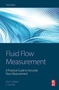
The basic PD design is a “bucket” that is alternately filled and emptied. To keep operation from being strictly batch operation, most PDs have multiple “buckets” that are geared and valved together so that while some buckets are filling, others are emptying. With proper timing and valving, there is an uninterrupted flow through the meter. The driving force for this action comes from the flowing stream as a pressure drop.
Readout is typically achieved electronically, although direct gearing to a Veeder-Root type counter allows a PD meter to be used at sites where no external power is available. When stopped, most PDs create a large blockage factor in the line. If there is a danger that the meter may be jammed, some means of bypass or relief must be designed, otherwise flow may be reduced to a very small percent of normal. In some cases a severe flow reduction may not be a critical concern, unless the pressure drop builds to a point that major damage is done to the meter. This problem is somewhat unique to PDs and must be examined before metering system designs are set.
Rangeability
One characteristic of PDs that makes them attractive is a rangeability that is unmatched by most other meters. They are able to measure very small flows in their stated ranges with relatively high accuracy. Since the meter’s flow path is normally not straight through, requirements of upstream and downstream piping are minimal and are normally based on piping space concerns rather than flow pattern considerations. Periodic maintenance and calibration must be allowed for in the design provisions to interrupt or bypass flow (Figure 12-8).

Design
Design of PD meters varies from device to device, and serves various portions of industry needs depending upon operational characteristics. For example, common to the natural gas industry are four-chamber/two-diaphragm meters, three-chamber meters with an oscillating valve, rotary meters of the roots type, meters with four rotating vanes and rotoseal meters. Liquid PD types include reciprocating piston, ring piston, rotating discs sliding vane, rotating vane, oval gear, nutating disc, metering pumps, and lobed impeller.
Standards and manufacturers’ literature should be consulted for operational details, sizing, range and accuracy limits, and recommended applications.
Because of the mechanical size of PD meters, limits on pressure, cost and weights become increasingly important as the meters get larger than about 10 inches. They are made in larger sizes, but the applications of these models are generally limited to special flow measuring situations.
Performance
PD meters perform well for long periods of time provided the fluids are clean, non-erosive, non-corrosive, non-depositing, and proper maintenance is routinely performed. Most major manufacturers also offer special designs for “hostile” fluids. In less critical measuring systems, such as domestic water and gas, meters are run for many years with testing only on the basis of statistical failure-rate study or upon customer complaint.
On the other hand, large liquid PD meters used in the petroleum industry may be tested on a weekly basis with a prover system permanently installed as part of the metering station.
There should be no overranging; if necessary, a protective flow-limiting device (with automatic bypass valve) should be installed to prevent the overranges, which mechanically damage the meter.
Equations
The equations for PD meters are the same as for turbine meters. Readout of the PD, which is at line volume conditions, is multiplied by a meter factor arrived at from proving and correcting factors to reduce flowing conditions of pressure, temperature, and compressibility at higher pressures to the base or contract conditions. (See Equations 12-7 through 12-9.)
Maintenance
Maintenance of small PD meters (below 4 inches) usually involves replacement, with repairs or rebuilding done at a central meter shop rather than in the field. With larger meters (6 inches and above), maintenance consists of part(s) replacement in the field and removal to a meter shop only if field repairs are unsuccessful. Maintenance decisions are based on the economics of maintenance costs versus the cost of inaccurate measurement.
1. Insensitive to upstream and downstream piping effects so that no, or minimum, lengths are required;
2. Operating principle straightforward, easy to understand;
3. Rangeability among highest of liquid and gas meters available without loss of accuracy;
4. Even though valving and clearances require close tolerances, commercially available units are rugged and provide long and reliable service on clean fluids or with line filters; and
5. Simple to complex readout systems available for a simple flow equation.
1. Because of clearances required, pressure, temperature, and viscosity ranges are limited and special care may be required for installation (meter specifications in this regard vary between manufacturers and should be examined carefully);
2. For larger sizes (above 10 inches), meters are large, heavy, and relatively expensive;
3. Head loss can be high, particularly if the meter jams; protection from flow shutdown and pressure overrange may be required;
4. Filtration or strainers may be required for fluids containing foreign particles to minimize meter wear; and
5. Maintenance costs are high on some larger meters; unit replacement is typical for smaller meters because of their complexity and field-repair cost.
Turbine Meters
Turbine meters are used successfully and widely in both liquid and gas measurement. They are made differently for gas and liquid measurement because of the difference in driving forces of the fluids and internal bearing frictions. However, the basic operation is the same for gas or liquid service.
The turbine meter is a velocity measuring device. Flow passes through a free-turning rotor mounted coaxially on the meter body centerline of the body. Since velocity is the parameter measured, the upstream downstream piping must have defined lengths to eliminate nonstandard velocity profiles and swirl (Figures 12-9, 12-10).


Fluid imparts an angular velocity to the angled rotor so that the rotation is proportional to the flow rate. Blade shape and angle, bearing style, and other construction details vary from manufacturer to manufacturer. With accurate measurement of rotor speed from mechanical gearing or magnetic pickup, and by knowing the hydraulic area that the flow is passing through, the volume at line conditions can be determined. Since no rotor is without friction, the aerodynamic friction across the rotor and the friction of the bearing system cause a non-linear calibration until the retarding forces are a small percentage of the driving forces. At this point, the calibration curve becomes linear (rotor speed increases directly with flow velocity).
The actual flow area is not the calculated open area, but something less because turbulence blocks some of it. Because of the friction, turbulence, and necessary manufacturing tolerances, each meter must be calibrated to determine its proof curve. The necessity for this calibration is different than for an orifice that can be manufactured to a tolerance that allows its calibration to be predicted from its mechanical shape; precise calibration for a turbine meter cannot be determined this way.
As flow through the turbine first increases from zero, a certain amount of fluid passes through the rotor before it begins to turn. At some point, the fluid imparts enough force to overcome the frictional retarding forces of the rotor bearing. At this point, the rotor begins to turn, and the friction forces in the bearing become small. The aerodynamic forces predominate and control the rotor’s speed. The existence of these retarding forces and the slight change in flow area create a difference between the theoretical and actual rotor speed. These differences must be accounted for with a calibration run on each meter. As the flow rate increases, these aerodynamic and bearing friction forces become minimal, and the proof curve becomes linear, reflecting only an increase in velocity.
There is another kinetic effect to consider. Fluid entering the meter is speeded up by a deflector before it passes through the rotor. More driving force results on the rotor because of the increased velocity and because the average velocity is being imparted further out on the rotor increasing the lever arm of the force. This improves the performance curve at lower flow rates. The flow deflector also serves to lessen thrust loads on the rotor bearing by shielding the center of the rotor from the flowing stream.
For gas meters, the deflector is larger (and the annular opening smaller), so it blocks approximately 66% of the meter area versus less than 20% for liquid meters. This generates higher velocities, hence torque, on the gas meters that operate in fluids with densities lower than those existing with liquid meters. The gas meters use sealed or shielded bearings for minimum friction and protection from line dirt accumulating; most liquid turbines use sleeve bearings of tungsten carbide for rugged wear characteristics.
Rangeability
The rangeability of a gas turbine meter varies with pressure—approximately 10 to 1 on a gas at atmospheric pressure to over 100 to 1 on a gas at pressures over 1,000 psia. On the other hand, liquid meters maintain a constant range of approximately 10 to 1 but have some overriding concerns for changes in viscosity, density, and meter size. As the viscosity rises above that of water, the meter range can be diminished down to as little as 3 to 1. Likewise, as densities drop to 60% of the density of water and lower, the range begins to decrease until it may reach 3 to 1. Smaller sizes (below 6 inches) tend to have lower ranges of linear proof curves. Each specific manufacturer should be consulted about the degradation of a meter range with viscosity, density, and size.
Meter capacity is determined by allowable rotor speed (bearing speed limit), pressure drop, and fluid velocity (blade angle). All manufacturers choose different design parameters, so their specific meters handle volumes which may be similar but not equal to that of another manufacturer (Figure 12-11).

Installation
Installation of a gas turbine must be done according to AGA-7 or ISO-9951 (draft). Liquid turbine meters must be installed according to Chapter 5 of the API Manual of Petroleum Measurement Standards for custody transfer metering. Other standards are more lenient in required lengths. Piping should be designed to allow for testing and removal of the meter for repairs as necessary, since neither liquid nor gas meters can be removed from an operating line without stopping flow and depressurizing. If the delivery requires flow continuity, then a bypass must be installed. (Note: The laws of some countries require metering continuity on any custody transfer meter.) If this is the case, then the bypass must include a meter. Sizing tables supplied by the meter manufacturer should be used in designing a meter station. If flow rates fluctuate, the range of the flows should be maintained within the turbine meter limits, particularly for low flow rates where meters have larger errors if the lower limits are exceeded.
Equations
The general turbine meter equation is:
(12.7)
qb=volume flow rate at base conditions;
qf=volume flow rate at operating conditions (meter reading);
Mf=meter factor to correct meter output based on calibration;
Equations for gas and the liquid meters are different. The gas turbine meter equation is as follows:
(12.8)
qb=volume flow rate at base conditions;
qf=volume flow rate at operating conditions (meter reading);
Mf=meter factor to correct meter output based on calibration;
Pf=pressure flowing conditions;
Pb=base pressure set by agreement near atmospheric pressure;
Tb=base temperature set by agreement at 60°F;
Tf=temperature at flowing conditions;
The liquid turbine meter equation is as follows:
(12.9)
qb=flow rate at base conditions;
qf=flow rate at operating conditions (meter reading);
Mf=meter factor to correct output based on calibration;
Ft=factor to correct fluid from flowing temperature to base temperature;
Fp=factor to correct fluid from flowing pressure to base pressure.
A turbine meter operates over its specified range with equal accuracy. Overranging by pressure drop can damage the blades, or high velocity can damage the bearings. This is a particular problem while putting meters in and taking meters out of service; at these times, flow rates must be changed slowly. Meters used with liquids that vaporize as pressure is removed from them require special filling techniques so that the meters are not damaged. This can be done by slowly filling the system with a gas while monitoring the rotor speed. Filling is continued until the pressure of the liquid is reached. The gas can be bled off slowly while the liquid is allowed to displace it without pressure drop and vaporization. When the liquid has completely filled the system, liquid flow may be started.
Maintenance and Calibration
Maintenance for properly operated turbines consists of periodic cleaning and physical inspection. Calibrations may be required to reconfirm proof curves on custody transfer meters. This may be done by calibration against standardized master meters or direct calibration against standards (i.e., critical flow nozzles for gas; pipe provers for liquids and gas).
1. Good accuracy over full linear range of meter (accuracy is percent of flow rate, not percent of full scale);
2. Electronic output available directly at high resolution rate which makes proving possible in a short time period with smaller prover time or volumes;
3. Meter cost is medium, but total meter station is low-to-medium cost because of high flow rate for given line size;
4. Has pressure and temperature limits, but can handle normal flow conditions very well; and
Disadvantages of turbine meters:
1. Require throughput proving to establish most accurate use;
2. Viscosity affects liquid meters that may require separate proof curves for different viscosities;
3. Rangeability at low pressures about the same as other gas meters; and
4. Require upstream flow pattern to be non-swirling, which necessitates straightening vanes.
Vortex Shedding Meters
The vortex shedding meter has come into prominence and usage in the last 20 years for both gas and liquid measurement. It has received acceptance in the industrial flow measurement area and, to a limited degree, in the custody transfer measurement area (Figure 12-12).
Although based on the same basic principle, various vortex shedding meters are standardized by performance, not in terms of mechanical construction of primary and secondary elements of the meter.
Operation
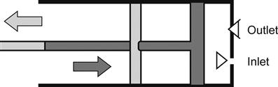
The vortex shedding meter operates on the Von Karman effect of flow across a bluff body. This principle states that flow will alternately shed vortices from one side and then the other of a bluff body, and the frequency of shedding is proportional to velocity across the body. When this velocity is combined with the hydraulic area of flow in a stream, the rate of flow can be established. Action is similar to the movement of a flag downstream of a flag pole. The rippling of the flag is due to the vortices as they are shed alternately on each side of the flagpole. Vortices may be counted in many ways, since the vortex represents a pressure and temperature change, and either of these may be sensed. Or, a secondary effect of the small movement at the bluff body can be used.
In any case, vortices are shed irregularly at low flows. When these stabilize, the meter’s lower flow rate is defined. Manufacturers have made continual developments in the readout systems and in determining the bluff body shape to give a strong, stable shedding pattern. Because of individual differences in the bluff body and the readout, each design is unique, and meter calibration should be obtained from the manufacturer.
Since the meter reacts to velocity, it follows that a proper flow pattern must be presented to the bluff body. This is accomplished by using straightening vanes, flow profile generators, and/or straight upstream piping to eliminate swirl distorted patterns. Installation requirements are similar to other velocity sensitive meters.
Sizing
The sizing of these meters with normal pipeline velocities makes throughput per line size higher than many other meters. Manufacturers’ sizing recommendations should be followed.
Equations
The equations for vortex flow meters are the same as those for turbine meters (Equations 12-7 through 12-9), since the meter produces a pulse output proportional to the flow rate at line conditions, and this output must be corrected from line conditions to base conditions. Depending on the individual meter, a calibration factor K is determined, which relates produced pulses to the line volume passed versus Reynolds number. These factors are supplied by the manufacturer based on calibrations covering a range of Reynolds numbers (liquid and gas) similar to the operating Reynolds numbers. The K curves are quite linear for flows above the low-end limit. Viscous liquid should be checked to make sure its Reynolds number at flowing conditions will exceed the low flow limit, usually in the 10,000 range.
Maintenance
As long as the bluff body and the meter body opening are kept clean, the meter should retain its original calibration. Any erosion, corrosion, or deposits that change the shape of the bluff body will cause a change in hydraulic area and will shift calibration. Periodic inspection is recommended to ensure that initial conditions are being maintained in the primary element.
The flow-variable correction instruments of the secondary system must be calibrated to insure that the transducers have not changed calibration. If recalibration of the primary element is required, then some type of throughput test is run against a standard.
Advantages of vortex shedding meters:
1. Relatively wide rangeability with linear output;
2. On clean fluids (liquids and gases), the meters have long-term stable proofs;
3. Frequency output can be read directly into electronic readout systems;
4. Installation costs moderate; installation simple;
5. When minimum or higher Reynolds numbers pertain, effects of viscosity, pressure, and temperature are minimal; and
Disadvantages of vortex shedding meters:
1. Flow into a meter must be swirl-free; this requires straightening vane and/or long, straight piping;
2. Output may have “jitter” (frequency instability) and/or fade in certain areas of operation which affect readout requirements;
3. Not available in sizes above 8 inches;
4. Pulse train is irregular, proving requires a long test time to obtain a representative average pulse rate;
5. Pulse resolution the same for all meter sizes; this means a low pulse rate with larger meters yields low volume resolution; and
Other and Special Purpose Meters
In addition to the more common meters covered above, other meters are available that are worthy of mention and a short description. When an application is contemplated, specific information should be obtained from suppliers of the meter.
Insertion meters are available in three types based on previously covered meters: turbine, vortex, and magnetic. An insertion meter is used to sample a velocity representative of the average velocity of a full stream. This limits their absolute accuracy to the validity with which the velocity sample point is located. However, their repeatability may be sufficient for some uses as a control device. Because of the small amount of flow blockage, insertion meters cause zero to small pressure drops compared to drops of equivalent full-bore meters (Figure 12-13). (Refer to previous material in this chapter for application suggestions and limits for the three meter types upon which insertion meters are based.)

Swirl meters have a fixed-geometry helix blade, which imparts a swirl upstream of a Venturi-shaped throat that increases the stream velocity. Deceleration in an expanding cone then follows. This action generates a precessing vortex (swirl) whose frequency is a function of flow velocity through the meter. A sensor then picks up the temperature change in the swirl or variation in pressure caused by the swirl. The meter is normally used on gas flows because of its high head loss on liquids. The complexity of mechanical construction involved requires calibration for each meter for best accuracy (Figure 12-14).

Special Application Meters
Certain flow meters have specific applications but are not considered for general use. The exclusion may be due to cost, or because the meter is newly developed or limited by its design/operation. This does not mean that at some future time there may not be further developments to expand a meter’s use. Such meter types include thermal, tracer, laser Doppler, nuclear magnetic resonance (NMR), and sonic nozzles.
Laser Doppler meters are similar in concept to Doppler ultrasonic meters but are more expensive and difficult to set up. For these reasons, they are more often used in research facilities for flow measurement. They require transparent pipe and flowing fluids that allow light to penetrate the flow stream (Figure 12-15).

Two light beams are focused on a particular area where flow velocity is to be measured. Any light-sensitive particles that pass this point scatter the light, which is then measured by a photo detector. The particle velocity causes a Doppler shift that produces a signal in the detector proportional to flow velocity at that point. Beams are moved across the flow to enough points to establish an average flow velocity.
These devices have definite use in studying flow profiles and patterns but have little use in converting a flow pattern to flow volume.
NMR meters mark the nuclei of hydrogen or fluoride in a flowing fluid. The fluid then enters a detector section when the magnetized nuclei relax between two detectors. This measurement produces a frequency proportional to fluid velocity within the detector section whose length and volume are known (Figure 12-16).

These devices, which are still in developmental infancy, are very expensive. However, their unique characteristics allow them to cover a wide range of difficult-to-measure flows (i.e., slurries, non-Newtonian fluids, and emulsions). Industrial applications are limited; most uses are in development and research work.
Sonic nozzles are specially shaped nozzles used for calibrating gas flow devices. A sonic nozzle is used mostly as a test device, because its high permanent pressure drop (10 to 15% of inlet pressure) is too costly to absorb in operations on a continual basis. It is quite accurate, provided that the thermodynamic properties of the flowing gas are known accurately. The most common use is as a calibration device for natural gas meters, such as PD or turbine meters used at over 35 psia pressure. Details on meter construction, calculation procedures, and use are available from meter manufacturers. The nozzles measure only one flow rate for a given static pressure and therefore are not used for normal flow measurement.
Thermal meters have been used for some research applications. However, developments are now beginning to make them attractive for some commercial (non-custody) flow jobs. These meters follow two basic operational principles:
1. A body is heated by known heat input, and the body is cooled by the flowing stream; this temperature change is proportional to mass flow rate.
2. A heat source adds heat to the stream, and downstream sensors measure the temperature rise which is proportional to mass flow rate (Figure 12-17).

The hot-wire anemometer is used to define flow velocity in a clean gas stream flow as the fluid cools the element. The element is operated at constant current, and its resistance is kept constant so voltage variations measured relate to velocity. In either case, the sensitivity of the element to fouling requires frequent cleaning even in clean streams; this limits the practical application of this type of meter in commercial measurement and makes it useful mainly in research.
Another way to use thermal energy for measurement is to install two thermistors in a flow stream, one in the flowing stream and the second in a side pocket out of the flowing stream. The temperatures of both probes are kept constant, and a measure of the difference of power supplied is proportional to the flow rate.
A similar meter measures the temperature before and after a heat source with both probes in the flowing stream.
All of these meters are so sensitive to problems of dirty streams that they find application mainly in determining low velocity mass flow rate of clean fluids.
Tracer meters have been around for many years. The first units injected a foreign substance into a flowing stream and then picked up its presence at one of two detectors downstream of the injection. One of the first such meters injected salt into the water. The details of injection, detection, dispersion, flow profile, distance between probes, and marker types have resulted in many different meters and makeups. They are used for spot checks of velocity and, with an area factor, allow volume calculation.
A marker must have some characteristic that sets it apart from the flowing stream, such as the salt in fresh water, radiation, heat, and dye properties. The tracer should be approximately the same density as the flowing stream. It should mix well and travel at the same speed as the carrier. It should be readily available at low cost, chemically inert, and not naturally exist as part of the stream. It should be detectable by some standard analysis technique such as conductivity, color, radioactivity, chromatographic analysis, flame ionization, photometry, or heat sensing.
Most tracers operate intermittently by manual injection, but some meters measure flow continually with automatic injection based on time or marker detection. Injection and detection points are based on distance and dispersion of the sample matched against detector sensitivity. The most accurate measurement with these devices requires calibration in place, but they can be used with less accuracy for lines already in place by adding the injector and detector(s). They are quite often used in control measurement to set flow rates where the absolute value of flow is not critical.