Proving Systems
Large volumes and/or high-value products and/or a need to reduce an unacceptable system balance necessitate proving a meter. Provers are permanently installed at larger facilities, or can be portable. For products of lower value, metering is assumed correct until a process goes out of control or a meter breaks down and requires repair or replacement.
The proving of meters for gas and liquid flow is discussed in this chapter, including the types in use, how they are used and the advantages and drawbacks of the different types.
Keywords
prover; proving; meter; gas; liquid; flow; calibrate; critical flow; measurement
The necessity of proving a meter depends on the value of accurate measurement for the product being handled (Figure 14-1). Large volumes and/or high-value products and/or a need to reduce an unacceptable system balance are the prime candidates for using provers. Oil industry measurement of crude oil and refined products are examples of where meters typically involve proving systems. The proving systems are considered part of the cost of the meter stations and are permanently installed at larger facilities. When product value is lower, provers are usually portable (used within a limited geographical area); as product value drops further, proving frequency is reduced, and for the lowest value products proving is not done at all.

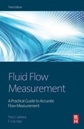
In other industries, proving in place is seldom done; metering is assumed correct until a process goes out of control or a meter breaks down and requires repair or replacement. For meters such as the orifice type, calibration is accepted to be correct as long as the mechanical requirements of the meter’s specifications are met. Some meters are “tested” by calibrating only the readout units, with no test or inspection of the primary device. This does not have the same value as a complete system examination or the use of a prover (Figure 14-2).
In summary, testing can be a very expensive and time-consuming procedure or it can be as simple as an external physical examination during a walk by. Obviously, the ability of these tests to prove a flow meter’s accuracy varies from the best that can be done to a “test” that really has nothing to do with flow accuracy. One of the easiest meter proving methods is to check the operating meter against a master meter that has a pedigree of accuracy and is adjusted for any differences in pressure and temperature. Any indicated registration differences can be calibrated into the operating meter by use of a meter factor applied manually or through an electronic meter adjustment. Meter factor in this case is defined as:
(14.1)
which “divides out” the meter indication and “multiplies in” the corrected volume.Since most meters are not totally linear, tests should be run over the meter’s operating range and the meter factor entered as an average factor over the range. Computers can apply a factor that varies with flow rate. The correction complexity required depends on the magnitude of meter non-linearity and the measurement’s accuracy requirements. Proving is common for liquid meters, but is rare for gas meter systems.
Liquid Provers
For products whose vapor pressure is the same or less than atmospheric pressure under flowing conditions, an open tank prover may be used as a standard or field test measure. Standardizing groups can calibrate field test measures/cans (Seraphins) and stamp on them either the volume they contain or volume they deliver. Flow from a meter is diverted on the run from normal delivery to fill the can. Readings of the operating meter are taken at the start and at the completion of the filling. This procedure can be automated by the use of solenoid valves in the fill and bypass system.
At one time, similar systems for testing fluids with vapor pressures greater than atmospheric were used with closed containers. But the cumbersome field test measures/cans required have been replaced with the more convenient pipe provers. Pipe provers are available in several configurations such as standard and small volume, U-shaped, straight or folded, ball or piston displacer, and unidirectional and bidirectional. The choice depends on parameters of the job to be done (Figure 14-3).

The bidirectional prover requires a displacer round trip to complete one prover run. It can be made U-shaped, folded, or straight, depending on space requirements.
The standard prover (U-shaped bidirectional) is the most common and uses an inflated ball displacer. Regardless of construction and operating details, all provers perform the same function.
Since proving creates a temporary slowdown in flow until the displacer gets up to speed, some pre-run length in the prover must be allowed before displacement of the accurately measured volume begins. At a point after flow rate stabilization, a switch indicates entry of the displacer into the calibrated section, and the meter pulses are sent to the proving counter or circuit.
Flow continues until a sufficient number of pulses (typically 10,000) have been generated by the operating meter. An exit switch then indicates that the calibration volume has been achieved, and pulses to the proving counter are interrupted. Pulses generated by the operating meter are thus “gated” to the proving counter, without stopping the same pulses from going to the billing meter’s counter. This displacer passage and collection of pulses is repeated a number of times (set by individual company policy but typically four or five), while the stabilized fluid pressure and temperature are recorded. Calculations convert the temperature and pressure to the same base conditions for the meter and the prover. When volumes are compared, the ratio of the prover to meter volume is the meter factor for this flow rate. Various provers have distinguishing characteristics (Figures 14-4, 14-5).


The small volume prover—
strong called a “compact” or “ballistic” prover—has a precise pickup system that allows less tolerance in the switch location for the displacer. The timing system requires fewer actual meter-generated pulses, since they are “multiplied” to generate the necessary pulse rate to achieve 10,000 pulses between switches. To minimize the pre-run and flow interruption when the displacer is launched, the displacer is driven externally rather than taking its energy from the flowing stream. This allows stabilization to be reached rapidly with a short pre-run. This system allows proving with less volume displaced, hence the name “small volume” prover.
However, if the meter does not produce a uniform pulse train then the captured pulse is not representative and the meter has difficulty achieving the required repeatability (Figure 14-6).

The unidirectional prover, built to send the displacer in only one direction, requires a volume large enough to produce the 10,000 meter-generated pulses.
The piston displacer prover uses a straight barrel design since the piston cannot go around a corner. It is used when the fluids, because of composition or temperature, make “standard” displacers unusable. The piston can use seals that will operate at temperature extremes and on most corrosive or reactive fluids. Since the seals operate on a smoothly machined or coated surface, the fluid stream should contain no erosive particles. Whatever the job to be done, a prover can be made to meet its requirements. As product value has climbed through the years and prover costs have dropped, many industries that in the past did not use these devices are now using them to improve their measurement, even at lower volume meter stations (Figures 14-7, 14-8).


Liquid Provers Summary
Proving systems are widely used in the petroleum industry as the basis for establishing flow meter accuracies as installed and operating on the operating fluid. A meter factor is determined and used until significant changes in flowing conditions occur.
Pipe provers are made in a number of different styles and shapes, and the choices are covered in API Standard Chapter 4 of the Manual of Petroleum Measurement Standards with details of their construction and use. Their proper use is the basis of accuracy in liquid flow measurement in the petroleum industry.
Gas Provers
In the past, gas meters have not been proved like liquid meters. Proving an orifice meter has involved making sure that the meter’s physical condition is maintained. In looking at ways to lower tolerances on gas meters of all kinds to reconfirm a meter or settle a concern over an individual meter’s accuracy, proving is used. This occurs when physical inspection is not sufficient (such as with a PD or turbine meter), to define errors and actual throughput testing with a pipe prover is used. Some operators are also beginning to use adaptations of them with orifice meters. Other provers may be master meters, critical flow provers, or a centralized proving facility where meters can be taken for accuracy confirmation.
Master meters are meters whose basic calibration has been certified, which can be placed in series with an operating meter for a comparative test. They can be made in special test units with a computer to control the equipment, collect the data, and calculate a meter factor.
For small, low pressure meter testing, a low pressure blower can provide the test medium. The meter is taken out of service, depressurized, and piped in series with the proving unit downstream. The blower then pulls air through the operating meter and the standard meter to obtain proofs at a series of flow rates. A meter factor curve, plotted from these tests, allows an average factor to be obtained.
At larger volume stations with higher pressures, a master meter can be piped in series with the operating meter for a test. A computer again controls system operation, calculates the data, and collects meter factors. This system can be remotely controlled from a central office. Periodically the master meter is returned to a standards lab or to the manufacturer for recertification.
All of these systems have been successfully used to improve measurement accuracies.
Critical Flow Provers
One of the oldest testing devices for gas meters is the critical flow prover. The prover is installed in series with an operating meter that has been bypassed. Gas at operating pressure is passed through the meter, and then the critical flow prover, which is normally vented to atmosphere. If there is a nearby gas pipeline with pressure lower than the operating line by at least 15%, the gas can be passed into the second line without interfering with the test, and the gas is not lost.
Several differently sized critical flow nozzles can be installed in sequence at a test holder, or a variable pressure can be used for testing over a range of rates with a single nozzle. Meter factors thus determined may be used to correct readings of the operating meters, or to initiate a complete inspection of the meter to bring them into agreement.
The thermodynamic properties of the flowing gas must be known to calculate the flow at critical conditions. The usefulness of the method breaks down if the gas is near its critical temperature and pressure, where correcting factors are not adequately known. Likewise, if the gas contains condensed liquids or if liquids condense in the nozzle, the critical flow device cannot be used. Any deposits of solids from the flowing stream change the nozzle’s throughput and must be removed before the nozzle is used for a test.
Critical flow nozzles are used to reconfirm meters (such as positive displacement and turbine meters) used in natural gas pipeline and distribution systems.
Pipe provers are similar to the small volume provers used in liquid testing; they have been developed and are used to determine gas meter accuracies (including those of orifice meters). The prover is piped in series with an operating meter, and a set volume is passed through the meter. Comparing prover volume to the indicated meter volume allows the factor to be determined. As the desire to reduce tolerances in measurement continues, this proving device is receiving additional attention and evaluation. Work to date indicates that, with careful testing and evaluating, a meter’s operating accuracy can be achieved and a meter factor determined.
Central Test Facility
Where enough meters are in service to justify a significant test program, some companies employ a system of trading out meters (or meter internals) and bringing them to a central facility for testing on a periodic basis such as once a year. For example, offshore meters are often taken to an onshore facility for recertification. The centralized location where a standardized test facility is set up should have good quality gas flows available. The standard may be a master meter and/or a critical flow prover.
Gas Proving Summary
For the systems discussed above, economics must be evaluated carefully to determine justification limits for each method. These provings are typically done in response to governmental requirements or company policies where there is sufficient accuracy payoff to justify the investment required. This normally means high volume, standard natural gas situations or high price specialty gas systems. The American Gas Association’s AGA Report No. 6, “Field Proving of Gas Meters Using Transfer Methods,” provides guidance and calculations for all of the various natural gas proving techniques discussed.