
Flow
The flow characteristics that are required for accurate measurement are discussed. These include: continuous, non-fluctuating, non-pulsating, and the pipe running full in liquid flow. Fluctuating or pulsating flow, or lack of full-conduit flow, causes measurement problems.
In the measurement of flow, output is desired in some unit of volume or of mass. The most common method used to measure flow rate or totalized flow is a volumetric meter to measure at line conditions and a densitometer or chromatograph to measure fluid density also at line conditions. These can be used to calculate a value at base conditions.
Each meter has certain requirements necessary for achieving its measurement potential. The heart of all this is the flow pattern entering the meter, which in general will be correct if the Reynolds number limit and the inlet piping agree with the original evaluation. The installation requirements for each meter must be met, for accurate results to be obtained. This chapter discusses these requirements in terms of the flow characteristics of the fluid.
Keywords
flow characteristics; measurement; accuracy; continuous; non-fluctuating; non-pulsating; full-conduit flow; unit; volume; density; Reynolds number
The flow characteristics of a fluid can aid or detract from the ease of making a measurement with a flow meter. Certain basic assumptions made previously in this book are amplified below.
Required Characteristics
The required characteristics of the flow include: continuous, non-fluctuating, non-pulsating, and the pipe running full in liquid flow.
“Continuous” means that the flow should not continually stop and start. Each meter has a certain amount of inertia to start, plus overshoot after a flow stops. Furthermore, during these periods, the inaccuracies of the low rate measurements are greater than the values typically quoted by manufacturers for specific meters.
On the other hand, startup and stop requirements for flow measurement are common for batch-type operations. No meter measures correctly from zero flow to normal flow. However, when totalized flow is the desired goal, short startup and shutdown times can be insignificant to a total flow, provided they correspond to a small percentage of the total flow time. Tanker loading of crude oil is an example of this type of operation (Figure 7-1).

For example, loading a supertanker may take 12 hours, and a start of eight minutes may be needed to get up to loading rate. It may take less than two minutes of the eight before a meter gets into its accurate range. This represents less than a few tenths of the total loading time and less than a hundredth of the total fluid loaded. Such a small error is usually compatible with the inaccuracy of the measuring system and typically can be ignored.
On the other hand, if a large portion of the metering time and/or much of the total flow happens at low rates, then a multiple meter system should be designed, or alternate meters should be evaluated. For large swings, the system might have one normal meter, one meter to measure at the low rate, and a third to handle an occasional peak. The key design parameter should be to minimize the percentage of the total measured flow represented by excursions of the flows.
When on-off flow operating control systems are required, then extended-flow-range metering systems must be used.
Fluctuating flow presents a problem when its rate of change falls outside the response time of the metering system. In such a case, the meter may appear to respond correctly, but the measurement accuracy can be severely compromised. Dampening readout systems to improve flow metering can severely increase measurement uncertainty. So much dampening can be applied that any meaningful indication of the actual flow is obliterated.
The proper method of dealing with this problem is to dampen the stream-flow variation so that the fluctuations remain within the meter system’s response time. If this is not possible, then a faster metering response time will be required.
Pulsation versus fluctuation relates to the frequency of flow changes. Pulsations may also come from pressure changes not directly related to flow but which can cause metering errors. In either case, the complexity of the problem strongly suggests that these variations in flow and/or pressure be removed before flow measurement is attempted. This problem is more prevalent in gas than liquid measurement.
Most commercially available metering systems do not have a response time fast enough to respond to flow pulsations more rapid than a few hertz. The effects of pump, compressor, control valve, or piping-created pulsations may exceed the meter’s response time. Here again, improper dampening of the readout system may make an operator happy with the flow record, but can introduce major flow readout errors—of over 100%.
Since recognizing pulsations significant enough to cause error in flow is very difficult, several instruments have been developed to help predict whether or not pulsation is causing flow measurement problems. None of these is capable of being used as a correction device; they are used only to discover pulsation and/or to show that the pulsation has been eliminated sufficiently to allow valid flow measurement.
Designing piping properly so as to minimize acoustic “tuning” in different meter systems can be a useful approach to minimizing problems in both the primary meter piping as well as in the secondary instrumentation. Experience has shown that a majority of the flow measurement problems with head meters caused by pulsation occur in the secondary instruments. Short, large-diameter piping to the differential meter is recommended, since such piping tunes only to very high frequencies (over 100 hertz), which are normally above the frequency that causes large flow errors. When pulsation is present, all statements of meter system accuracy are suspect. The pulsations should be eliminated before flow measurement is attempted (Figure 7-2).

Full-conduit flow is important in liquid systems. The flowing pipe must run full, or any measurements made will be in error. This can be a problem if piping design does not keep the meter below the rest of the piping. If the meter is at the high point, then vapor can collect and create a void in the meter so any velocity or volume displacement measured will be in error.
Measurement Units
In the measurement of flow, output is desired in some unit of volume or of mass. Volume flow rate or totalized volume measured at line conditions does not represent a defined quantity without a definition of the base conditions; they cannot be combined with other volumes whose fluid and line conditions are different. However, volume flow rate or totalized volume corrected to base conditions is a definitive quantity which can be combined with other values also at base conditions. Values of volume and mass at base conditions are related to each other through density at line conditions (mass value divided by base density). The most common method used to measure flow rate or totalized flow is a volumetric meter to measure at line conditions and a densitometer or chromatograph to measure fluid density also at line conditions. Mass flow rate or totalized mass may be measured directly with a direct mass meter.
If fluid density varies by more than about ±0.15% during a totalization period, then the conversion must be performed on a flow rate-weighted basis, or the conversion should be calculated more frequently to obtain the desired uncertainty. Depending on the billing requirements, other factors such as the heating value of individual components (which may have individual price values) may have to be derived from these base flow measurements, or determined with a Btu chromatograph.
Proper base conditions are normally determined by plant/sales contract, government requirements or operating agreement.
Installation Requirements
Each meter has certain requirements necessary for achieving its measurement potential. The requirements vary between meters and types of meters; refer to the specific meter section, standards, and manufacturers for details. They are determined by standards organizations, users, manufacturers, and research laboratories. In each case, the performance characteristics of the meter depend on these requirements being met. Any lessening of the specifications means that performance is compromised, and specific calibrations in place should be run (Figure 7-3).

Most meters have been developed from some basic principles embodied in a prototype. These prototypes may go through several development iterations, but if they prove out in flow tests, they become a marketable product. Except in special cases, most meters are designed for general usage and are tested accordingly. During these tests, effects on meter performance from flow into and out of the meter are determined and installation requirements are set. With sufficient experience in a given industry, plus additional tests, a standard may be prepared to guide users on the meter’s installation requirements.
As time passes and additional applications are checked, these requirements may be adjusted to reflect new knowledge. Whatever the source, data should be checked to assure a user that the application has been evaluated and the design data are valid for the specific job requirements.
Flow Pattern
The heart of all this is the flow pattern entering the meter, which in general will be correct if the Reynolds number limit and the inlet piping agree with the original evaluation. The installation will then be proper. If a flow measurement practitioner deviates from the tested design, most meter manufacturers make no claim about their meter’s performance and simply state that minimum piping requirements must be met.
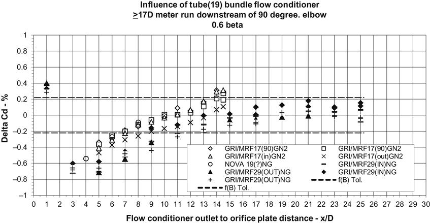
This means two things are important: 1) familiarity with installation requirements is a must, and 2) the minimum requirements must be met to make sure no errors are introduced due to installation. Some meters have a defined flow pattern requirement (i.e., the amount of distortion of the flow pattern and/or swirl allowed), but this is rarely checked when a meter arrives in the field. Recent work has indicated that additional flow pattern preparation is necessary to reduce the inaccuracies in meters with heightened sensitivity to flow profile variation. This has required changes in installation requirements for flange-tapped orifice meters as seen in ANSI/API 14.3/AGA Report. No.3, Part 2, to maintain proper flow patterns.Much of the significant research into installation requirements has been conducted by the AGA-API and other international committees responsible for writing standards on orifices. The influence of installation effects can be seen in Figures 7-3a through 7-3d. These figures show the installation effects’ influence on the orifice plate coefficient of discharge, Cd, from a relatively ordinary isolated long radius 90 degree elbow disturbance. Figures 7-3a and 7-3b show the influence on 17D upstream meter tubes without any flow conditioning (bare tubes) and two different diameter ratios (β), 0.6 and 0.4. Figures 7-3c and 7-3d show the influence on a 17D upstream meter tube with 19 tube uniform straightening vanes and two different diameter ratios (β), 0.6 and 0.4. The bare meter tube and straightening vane meter tube data show that upstream meter tube lengths recommended in the 1992 standards were inadequate to prevent errors in the measurement, and these were revised in 2000. In addition the research data indicated that the installation effects’ influence could be minimized in existing meters by reducing the diameter ratios (β) to 0.4.


A limited amount of work has also been conducted with linear meters, mostly gas and liquid turbine meters and ultrasonic meters.
From a design standpoint, the best interpretation of these revised requirements is to use the worst case (most disturbed profile) and design to it using the highest Reynolds numbers (the largest beta ratio) so meter tubes will be of a universal length that is independent of actual piping upstream or downstream. The result will be meter tubes which are longer than required by the standard for a particular application, but the standards provide minimum requirements, and longer meter tubes are better if space permits. The same philosophy applies to meter tubes for any type of meter where upstream/downstream piping is a consideration.
Flow pattern distortion comes from upstream pipe fittings, foreign material in the meter tube, or improperly made or aligned meter tubes. Any of these will cause an asymmetrical flow pattern with the possibility of swirl. Asymmetrical profiles can cause errors in the 0–3% range with differential meters and ultrasonic meters, but errors are generally less for intrusive linear meters such as turbine and positive displacement (PD). Errors from swirl may be in the 1–6% range for differential meters and generally more (1–10%), depending on swirl direction and magnitude, for other types of meters
Obviously, swirl is the major concern. If there is any question of swirl being present, straightening vanes should be used. Experience has indicated that swirl can propagate even in extra-long (250 nominal pipe diameters) upstream piping. Tank/vessel outlets and parallel meter tube headers are known to generate 10 to 50 degrees swirl angle magnitude. The better design is to minimize changes in direction and planes of flow upstream of the meter. If swirl is not generated, it obviously will not be propagated (Figure 7-4).

In addition to generating swirl, upstream meter piping can create or minimize other problems. High velocities across blocked in-line tees can create vortices in both the tee and the line. This can set up fluctuations or pulsations that make flow metering difficult. On gas lines that may drop out liquids, pockets of liquids can also create variable flow rates as the fluids wash back and forth. Drips with drains should be put in low spots to drain this liquid away (Figure 7-5).

If pipelines are very dirty, it may be necessary to install scrubber/filters to filter fluids and solids out of gases, and solids and gases out of liquids. On liquid lines, where gas or vapor may be present, air/vapor eliminators should be installed or flow fluctuations may result. Sizing of upstream headers should be controlled so that velocities are slowed in the lines leading to meter runs.
A useful rule of thumb is that the area of the header should be one-and-a-half to two times the area of all of the meter runs off it. An alternate rule is to have velocity in the headers half of that in the meter tubes. This will provide good flow distribution to the meters and minimize flow profile problems caused by the headers.