
Chapter 5 Orthographic Views
5-1 Introduction
This chapter introduces orthographic views. Orthographic views are two-dimensional views of three-dimensional objects. Orthographic views are created by projecting a view of an object onto a plane which is usually positioned so that it is parallel to one of the planes of the object. See Figure 5-1.

Figure 5-1
Orthographic projection planes may be positioned at any angle relative to an object, but in general, the six views parallel to the six sides of a rectangular object are used. See Figure 5-2. Technical drawings usually include only the front, top, and right-side orthographic views because together they are considered sufficient to completely define an object’s shape.

Figure 5-2
5-2 Three Views of an Object
Orthographic views are positioned on a technical drawing so that the top view is located directly over the front view, and the side view is directly to the right side of the front view. See Figure 5-2.
The locations of the front, top, and right-side views relative to each other are critical. Correct relative positioning of views allows information to be projected between the views. Vertical lines are used to project information between the front and top views, and horizontal lines are used to project information between the front and right-side views.
Orthographic views are two-dimensional, so they cannot show depth. In Figure 5-2, plane A–B–C–D appears as a straight line in both the front and top orthographic views. Edge A–B appears as a vertical line in the top view, as a horizontal line in the side view, and as point AB in the front view. The end view of a plane is a straight line, and the end view of a line is a point. See Figure 5-3.

Figure 5-3
Figure 5-4 shows an object and the front, top, and right-side orthographic views of the object. Plane A–B–C–D appears as a rectangle in the front view and as a line in both the top and right-side views.

Figure 5-4
To help you better understand the relationship between orthographic views and, in particular, the front, top, and side views of an object, place a book on a table as shown in Figure 5-5. Note how the front, top, and side views were projected and then arranged to create a technical drawing of the book.

Figure 5-5
5-3 Visualization
Visualization is the ability to look at a three-dimensional object and mentally see the appropriate three orthographic views.
It is an important skill for a designer and an engineer to develop. Visualization also includes the ability to look at two-dimensional orthographic views and mentally picture the three-dimensional object that the views represent.
Figure 5-6 shows a 5 × 3.5 × 2-inch box and three orthographic views of the box. The creation of three-dimensional object drawings is explained in detail in Chapters 14, 15, and 16. This section presents a short exercise to help you better understand how orthographic views are related to three-dimensional objects.

Figure 5-6
To Draw a Three-Dimensional Box
 Set the AutoCAD drawing screen for inches, and then select the 3D View command from the View menu accessed by clicking first the Menu Browser in the upper-left corner of the screen, then SE Isometric.
The origin axis reference icon will change to the 3D alignment.
 Type the word box to a command prompt.
Specify corner of box or [Center] <0,0,0>:
 Press Enter.
Specify corner or [Cube/Length]:
 Type L; press Enter.
Specify length:
 Type 5; press Enter.
Specify width:
 Type 3.5; press Enter.
Specify height:
 Type 2; press Enter.
A box will appear on the screen.
 Select the 3D Orbit command from the View menu. Move the cursor around the drawing screen, holding the left mouse button down. Position the box so as to create each of the three orthographic views shown in Figure 5-6.
Figures 5-7 and 5-8 show two additional objects and their orthographic views.

Figure 5-7

Figure 5-8
5-4 Hidden Lines
Hidden lines are used to represent surfaces that are not directly visible in an orthographic view. Figure 5-9 shows an object that contains a surface that is not visible in the right side view. A hidden line is used to represent the end view of the surface.

Figure 5-9
Figure 5-10 shows an object and three views of the object. The top and side views of the object contain hidden lines.

Figure 5-10
Figure 5-11 shows an object that contains an edge line A–B. In the top view of the object, line A–B is partially hidden and partially visible. When the line is directly visible through the square hole, it is drawn as a continuous line; when it is not directly visible, it is drawn as a hidden line.

Figure 5-11
5-5 Hidden Line Conventions
Figure 5-12 shows several conventions associated with drawing hidden lines. Whenever possible, show intersections of hidden lines as touching lines, not as open gaps. Corners should also be shown as touching lines.

Figure 5-12
Figure 5-13 shows two hidden lines and a continuous line that are aligned. A small gap should be included between the two types of lines to prevent confusion as to where one type of line ends and the other begins. A visual distinction can also be created by selecting a different color for hidden lines. If continuous and hidden lines are drawn with different colors, then gaps are not necessary.
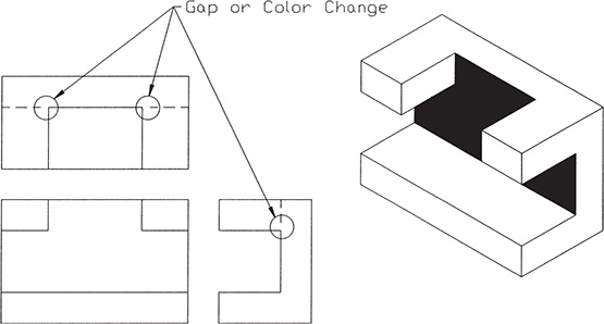
Figure 5-13
5-6 Drawing Hidden Lines
Hidden lines may be created in several different ways, but two of the easiest options are to modify an existing continuous line or to transfer an existing continuous line to a layer created specifically for hidden lines. In the examples presented, both linetype and line color will be changed.
To Add Hidden Linetypes to the Drawing
- Type the word Linetype in response to a command prompt.
The Linetype Manager dialog box will appear. See Figure 5-14.

Figure 5-14
- Click the Load box on the Linetype Manager.
The Load or Reload Linetypes dialog box will appear. See Figure 5-15.

Figure 5-15
- Scroll down the linetypes, and select HIDDEN linetype.
- Click OK, and OK again to return to the drawing screen.
The HIDDEN line should appear in the Linetype Manager box.
- Draw a line as shown in Figure 5-16.

Figure 5-16
- Click the line.
Grip points will appear on the line, along with a dialog box.
- Right-click the mouse and select the Properties option.
The Properties palette will appear.
- Click the Linetype line, scroll down, and select the HIDDEN linetype.
 Click the Color line, and select the Blue color.
See Figure 5-17. The line now has a hidden linetype and is blue.

Figure 5-17
 Close the Properties palette and dialog box. Click the large X in the upper-left corner of the box.
 Press the <Esc> key.
To Create a Hidden Layer for General Use
Create a hidden layer so that any line can be transferred to that layer, creating a hidden blue line.
- Click the Layer Properties tool located on the Layers panel under the Home tab.
The Layer Properties Manager dialog box will appear. See Figure 5-18.

Figure 5-18
Note
Click and drag the right edge of the Layer Properties Manager to extend the width of the box.
- Click the New Layer tool.
A new layer listing, Layer1, will appear below the 0 layer.
- Change the Layer1 name to Hidden.
- Scroll across the Hidden layer line, and click the word Continuous under the Linetype heading.
The Select Linetype dialog box will appear.
- Click the Hidden line on the Select Linetype dialog box, and click OK.
- Repeat the procedure, and change the hidden line’s color to blue.
- Close the Layer Properties Manager.
To Change Layers
Figure 5-19 shows a continuous line drawn on the 0 layer.

Figure 5-19
- Click the line.
- Click the Layer tool and scroll down, selecting the Hidden layer.
See Figure 5-19.
- Press the <Esc> key.
The line is now located on the Hidden layer, has a hidden linetype, and is blue.
The line’s linetype and color could have been changed by the Quick Properties option shown in Figure 5-20. Access the Quick Properties option by clicking the line and then right-clicking the mouse. The Quick Properties option is at the bottom of the dialog box.

Figure 5-20
Figures 5-21 and 5-22 show an object and three views of that object. There are hidden lines in several of the orthographic views.

Figure 5-21

Figure 5-22
5-7 Precedence of Lines
When orthographic views are prepared, it is not unusual for one type of line to be drawn over another type—a continuous line over a centerline, for example. See Figure 5-23. Drawing convention has established a precedence of lines: A continuous line takes precedence over a hidden line, and a hidden line takes precedence over a centerline.

Figure 5-23
If different linetypes are of different lengths, include a gap where the line changes from continuous to either hidden or center in order to create a visual distinction between the lines. Color changes may also be used to create visual distinctions between lines.
5-8 Slanted Surfaces
Slanted surfaces are surfaces that are not parallel to either the horizontal or vertical axis. Figure 5-24 shows a slanted surface A–B–C–D. Slanted surface A–B–C–D appears as a straight line in the side view and as a plane in both the front and top views. It is important to note that neither the front view nor top view of surface A–B–C–D is a true representation of the surface. Both orthographic views are actually smaller than the actual surface. Lines B–C and A–D in the top view are true length, but lines A–B and C–D are shorter than the actual edge lengths. The same is true for the front view of the surface. The side view shows the true length of lines A–B and D–C. True lengths of lines and true shapes of planes are discussed again in Chapter 7, Auxiliary Views.

Figure 5-24
Figure 5-25 shows another object that contains slanted surfaces. Note how projection lines are used between the views. As objects become more complex, the shape of a surface or the location of an edge line will not always be obvious, so projecting information between views—and therefore, exact, correct relative view location—becomes critical. Information can be projected only between views that are correctly positioned and accurately drawn.

Figure 5-25
5-9 Projection Between Views
Information is projected between the front and side views by using horizontal lines, and between the front and top views by using vertical lines. Information can be projected between the top and side views by using a combination of horizontal and vertical lines that intersect a 45° miter line. See Figure 5-26.

Figure 5-26
A 45° miter line is constructed between the top and side views. This line allows the project lines to change direction, turn a corner, and change from horizontal to vertical lines. To go from the top view to the side view, horizontal projection lines are constructed from the top view so that they intersect the miter line. Vertical lines are constructed from the intersection points on the miter line into the side view. The reverse process is used to go from the side view to the top view.
The following sample problem shows how projection lines can be used to create orthographic views through AutoCAD.
5-10 Sample Problem SP5-1
Draw the front, top, and right-side orthographic views of the object shown in Figure 5-26. Set up the drawing as follows:
- Create a separate layer for hidden lines.
Limits = 297 × 210 (Metric setup)
Grid = 10
Snap = 5
Ortho = ON (F8)
Layer = HIDDEN (LType = HIDDEN, Color = Green)
- Use the overall dimensions (length = 80, height = 50, and depth = 40) to define the overall size requirements of the three orthographic views. See Figure 5-27. The 20 spacing between the views is arbitrary. The distance between the front and top views does not have to equal the distance between the front and side views. In this example, the two distances are equal.

Figure 5-27
- Draw a 45° miter line starting from the upper-right corner of the front view. This step is possible only if the distances between the views are equal. If the distances are not equal, draw the front and top views, add the miter line, and project the overall size of the side view from the front and top views.
3a. (Optional) Trim away the excess lines to clearly define the areas of the front, top, and side views.
3b. (Optional) The Layer tool may be used to create a layer for construction lines and another layer for final drawing lines. The lines for the final drawing may then be transferred to the final drawing layer, and the construction layer turned off. This method eliminates the need for extensive erasing or trimming.
- Draw the 45° slanted surface in the front view as shown in Figure 5-27. Project the intersection of the slanted surface and the top edge of the front view into the top view. Add a horizontal line across the front and right-side views 25 from the bottom edge line. The 25 value comes from the given dimension. Label the intersection of the slanted line and the horizontal line as point A.
- Draw a horizontal line in the top view 20 from the top edge as shown in Figure 5-27. Continue the line so that it intersects the miter line. Project the line into the side view. Use Osnap Intersection with Ortho on to ensure an accurate projection. Label point A in the side view.
- Project point A in the front view into the top view (vertical line). Label the intersection of the projection line and the horizontal line in the top view as point A.
- Use Erase and Trim to remove the excess lines.
- Save the drawing if desired.
5-11 Compound Lines
A compound line is formed when two slanted surfaces intersect. See Figure 5-28. The true length of a compound line is not shown in the front, top, or side views.

Figure 5-28
Figure 5-29 shows another object that contains compound lines. The three orthographic views of a compound line are sometimes difficult to visualize, making it more important to be able to project information accurately between views. Usually, part of an object can be visualized and part of the orthographic views created. The remainder of the drawing can be added by projecting from the known information.
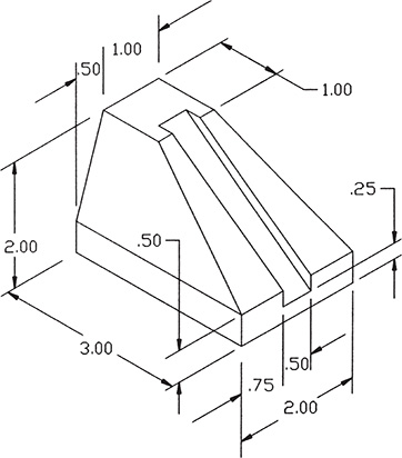
Figure 5-29
5-12 Sample Problem SP5-2
Figure 5-30 shows how the front, top, and side views of the object shown in Figure 5-29 were created by projecting information. The procedure is as follows:

Figure 5-30
- Set the drawing up as follows:
Limits = Default
Grid = .5
Snap = .25
- Use the overall dimensions to define the space and location requirements for the views. Draw the 45° miter line.
- Use the given dimensions to define the starting and end points on the compound lines in the top and front views. One of the lines has been labeled A–B.
- Draw the compound line in the top view, and then project it into the side view, using information from both the top and front views.
- Add the dovetailed shape, using the given dimensions. Draw the appropriate hidden lines for the dovetail.
- Erase and trim the excess lines.
- Save the drawing if desired.
Figure 5-31 shows the three orthographic views and pictorial view of another example of an object that includes compound lines. Some of the projection lines have also been included.

Figure 5-31
5-13 Oblique Surfaces
Oblique surfaces are surfaces that do not appear correctly shaped in the front, top, or side views. Figure 5-32 shows an object that contains oblique surface A–B–C–D. Figure 5-32 also shows three views of just surface A–B–C–D. Oblique surfaces are projected by first projecting their corner points and then joining the points with straight lines. The orthographic views of oblique surfaces are sometimes visually abstract. This makes the development of their orthographic views more dependent on projection than other types of surfaces.

Figure 5-32
Figure 5-33 shows another object that contains an oblique surface. Figure 5-34 shows how the three orthographic views were developed. The oblique surface is defined by using only two angles, but this is sufficient to create the three views because the surface is flat. The edge lines are parallel. Lines A–B, C–D, and E–F are parallel to each other, and lines C–B, D–E, and F–A are also parallel to each other. Figure 5-34 also shows three views of just the oblique surface, along with the appropriate projection lines.

Figure 5-33

Figure 5-34
5-14 Sample Problem SP5-3
The three views of the object shown in Figure 5-35A may be drawn as follows. (The given dimensions are in millimeters.)

Figure 5-35A
- Use the Line and the Offset commands to set up the sizes and locations of the three views. Use Osnap Intersection to draw the projection lines. See Figure 5-35B.

Figure 5-35B
- Draw an oblique surface based on the given dimensions. The edge lines of the oblique surface are parallel.
- Draw the slanted surface in the side view, and project the surface into the other views. Use the intersection between the slanted surface and flat sections on the top and side of the object to determine the shape of the oblique surface.
- Use Erase and Trim to remove any excess lines. Save the drawing if desired.
5-15 Rounded Surfaces
Rounded surfaces are surfaces that have constant radii, such as arcs or circles. Surfaces that do not have constant radii are classified as irregular surfaces. See Section 5-24.
Figure 5-36 shows an object with rounded surfaces. Surface A–B–C–D is tangent to both the top and side surfaces of the object, so no edge line is drawn. This means that the top and side orthographic views of the object are ambiguous. If only the top and side views are considered, then other interpretations of the views are possible. Figure 5-36 shows another object that generates the same top and side orthographic views, but does not include rounded surface A–B–C–D. The front view is needed to define the rounded surfaces and limit the views to only one interpretation.

Figure 5-36
Surfaces perpendicular to an orthographic view always produce lines in that orthographic view. The vertical surface shown in the front view of Figure 5-37A requires an edge line in the top view. The vertical line in the front view is perpendicular to the top views.

Figure 5-37
The object shown in Figure 5-37B has no lines perpendicular to the top view, so no lines are drawn in the top view. Figure 5-37C shows two rounded surfaces that intersect at points tangent to their centerlines. The intersection point is considered sufficient to require an edge line in the top view. No line would be visible on the actual object, but drawing convention prescribes that a line be drawn.
Figure 5-38 shows an object that contains two semicircular surfaces. Note how lines representing the widest and deepest point of the surfaces generate lines in the top view. No line would actually appear on the object. Figure 5-39 shows further examples of objects with curved surfaces.

Figure 5-38

Figure 5-39
5-16 Sample Problem SP5-4
Figure 5-40 shows an object that includes rounded surfaces, and Figure 5-41 shows how the three views of the object were developed.

Figure 5-40

Figure 5-41
The procedure is as follows:
- Use the given overall dimensions to lay out the size and location of the three views.
- Draw in the external details, the cutout, and the circular extension in all three views.
- Add the appropriate hidden lines. Either use the Modify Properties option or create a layer for hidden lines.
- Erase and trim any excess lines, and save the drawing if desired.
5-17 Holes
Holes are represented in orthographic views by circles and parallel hidden lines. All views of a hole always include centerlines. See Figure 5-42. It is suggested that a layer titled Center be added to any drawing being created. Specify the linetype Center and the color Red.

Figure 5-42
Holes that go completely through an object are dimensioned by the use of only a diameter. The notation THRU may be added to the diameter specification for clarity.
Holes that do not go completely through an object include a depth specification in their dimension. The depth specification is interpreted as shown in Figure 5-42. Holes that do not go completely through an object must include a conical point. The conical point is not included in the depth specification. Conical points must be included because most holes are produced by using a twist drill with conically shaped cutting edges.
The cutting angles of twist drills vary, but they are always represented by a 30° angle, as shown.
Figure 5-43 shows an object that contains two through holes and one hole with a depth specification. Note how these holes are represented in the orthographic views and how centerlines are used in the different views.

Figure 5-43
Figure 5-44 is another example of an object that includes a hole. The hole is centered about the edge line between the two normal surfaces. Figure 5-45 shows the same object with the hole’s center point offset from the edge line between the two normal surfaces. Compare the differences between Figures 5-44 and 5-45.

Figure 5-44

Figure 5-45
5-18 Holes in Slanted Surfaces
Figure 5-46 shows a hole that penetrates a slanted surface. The hole is perpendicular to the bottom surface of the object. The top view of the hole appears as a circle because we are looking straight down into it. The side view shows a distorted view of the circle and is represented by an ellipse.

Figure 5-46
The shape of the ellipse in the side view is defined by projecting information from the front and top views. Points 1 and 2 are known to be on the vertical centerline, so their location can be projected from the front view to the side view by using horizontal lines. Points 3 and 4 are located on the horizontal centerline, so their location can be projected from the top view into the side view by the 45° miter line.
The elliptical shape of the hole in the side view is drawn, connecting the projected points, by using the Ellipse command.
To Draw an Ellipse Representing a Projected Hole
See Figure 5-47.

Figure 5-47
- Define the first point as one of the points at which the major axis intersects one of the centerlines.
- Define the second point as the other point on the major axis that intersects the same centerline.
- Define the third point as one of the points on the minor axis that intersects the centerline perpendicular to the centerline used in steps 1 and 2.
To Draw Three Views of a Hole in a Slanted Surface
Figure 5-48 shows an object that includes a hole drilled perpendicular to the slanted surface. The hole is 1.00 unit in diameter. The hidden lines in the front view that represent the edges of the hole are drawn parallel to the centerline at a distance of 0.50. The horizontal and vertical centerlines of the hole are located in the top and right views. The intersection of the hole edges with the slanted surface shown in the front view is projected into the top and side views as shown.

Figure 5-48
The slanted surface shown in Figure 5-48 appears as a straight line in the front view. This means that the hole representations in the top and side views are rotated about only one axis. This, in turn, means that the hole representation is foreshortened in only one direction. The other direction—the other axis length—remains at the original diameter distance on 1.00. The four points needed to define the projected elliptical shape can be defined by the projection lines and the measured 1.00 distance.
The hole also penetrates the bottom surface, forming a different-sized ellipse. The hole’s penetration can be shown in the side view by hidden lines parallel to the given centerline. The elliptical shape in the top view is defined by drawing horizontal parallel lines from the intersection of the hole’s projected shape with the vertical centerline, and by projection lines from the front view that define the hole’s length.
To Draw Three Views of a Hole Through an Oblique Surface
Figure 5-49A shows a hole drilled horizontally through the exact center of an oblique surface of an object. The oblique surface means that both axes in the top and front views will be foreshortened. The procedure used to create the hole’s projection in the front and top views is as follows. (See Figure 5-49B.)
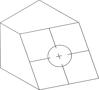
Figure 5-49A

Figure 5-49B
- Draw the hole in the side view. The hole will appear as a circle because it is drilled horizontally.
- Draw the hole’s centerlines in the front and top views. The hole is located exactly in the center of the oblique surface, so lines parallel to the surface’s edge lines located midway across the surface may be drawn.
- Project the intersection of the hole and the horizontal centerline into the top view, and project the intersection of the hole with the vertical centerline into the front view.
- Project the intersections created in step 3 with the horizontal centerline, represented by the slanted centerline, onto the horizontal centerline in the front view. Likewise, project the intersection points created in step 3 on the horizontal centerline in the front view to the slanted centerline in the top view.
- Draw the ellipses as required, add the appropriate hidden lines, and erase and trim any excess lines. Save the drawing if desired.
5-19 Cylinders
Figure 5-50 shows three views of a cylinder that is cut along the centerline by surface A–B–C–D. Note that each of the three views includes centerlines. The front and top views of a cylinder are called the rectangular views, and the side view (end view) is called the circular view. The width of the top view is equal to the diameter of the cylinder.

Figure 5-50
Figure 5-51 shows a cylinder that has a second surface located above the centerline in the front view. The top view of the cylinder shows the flat surface and the rounded portion of the cylinder. Both the flat surface and the two rounded surfaces appear as rectangles.

Figure 5-51
Figure 5-52 shows a cylinder with a surface J–K–L–M that is located below the centerline in the front view. The top view of this surface does not include any rounded surfaces, because they have been cut away.

Figure 5-52
5-20 Sample Problem SP5-5
Figure 5-53 shows a cylindrically shaped object that has three surface cuts: one above the centerline, one below the centerline, and one directly on the centerline. Figure 5-54 shows how the three views of the object were developed. The procedure is as follows:

Figure 5-53

Figure 5-54
- Use the given overall length of the cylinder and its diameter to create the two rectangular top and front views and the circular end views.
- Draw horizontal lines in the side view that define the end views of the three surfaces. Project the size and location of the surfaces into the front and top views. Use Osnap Intersection, with Ortho on, for accurate projection.
- Erase and trim the excess lines.
- Save the drawing if desired.
5-21 Cylinders with Slanted and Rounded Surfaces
Figure 5-55 shows a front and side view of a cylindrical object that includes a slanted surface. Slanted surfaces are projected by defining points along their edges in known orthographic views and then projecting the edge points. At least two known views are needed for accurate projection. Sample Problem SP5-6 shows how to define and project a slanted cylindrical surface into the top view, given the front and side views.

Figure 5-55
5-22 Sample Problem SP5-6
(See Figure 5-56.)

Figure 5-56
- Draw the rectangular shape of the top view by projecting the length from the front view and the width from the side view.
- Project the centerlines, and label points 1, 2, and 3 in the front and side views. The locations of these points are known from the given information.
- Draw three horizontal lines across the front and side views. The location of the lines is arbitrary. Label the intersections of the horizontal lines with the edge of the slanted surface as shown.
- The three horizontal lines serve to define point locations along the surface’s edge.
A line contains an infinite number of points, so any six can be used.
- Draw vertical projection lines (Osnap Intersection) from the six point locations in the front view into the area of the top view.
- Project the six point locations from the side view into the area of the top view. Use the 45° miter line to make the turn between the two views. The intersection of the vertical projection lines of step 2 and the projection lines from the side view defines the location of the points in the top view. Label the six points.
- Use Draw, Polyline, Edit Polyline, and Fit to create a smooth line between the six projected points.
- Remove any excess lines, and save the drawing if desired.
Figure 5-57 shows another cylindrical object that contains a slanted surface along with some of the projection lines.

Figure 5-57
5-23 Drawing Conventions and Cylinders
A hole drilled into a cylinder will produce an elliptically shaped edge line in a profile view of the hole. See Figure 5-58. Drawing convention allows a straight line to be drawn, in place of the elliptical shape, for small holes. The elliptical shape should be drawn for large holes in cylinders—that is, one whose diameter is greater than half the diameter of the cylinder.

Figure 5-58
Drawing convention also permits straight lines to be drawn for the profile view of a keyway cut into a cylinder. See Figure 5-59. As with holes, if a keyway is large relative to a cylinder, the correct offset shape should be drawn. A keyway is considered large if its width is greater than half of the diameter of the cylinder.

Figure 5-59
5-24 Irregular Surfaces
Irregular surfaces are curved surfaces that do not have constant radii. See Figures 5-60 and 5-61. Irregular surfaces are defined by the X,Y coordinates of points located on the edge of the surface. The points may be dimensioned directly on the view, but are often presented in chart form, as shown in Figure 5-61. Figure 5-61 also shows a wing surface defined relative to a given X,Y coordinate system.

Figure 5-60

Figure 5-61
Irregular surfaces are projected by defining points along their edges and then projecting the points. At least two known views are needed for accurate projection. The more points used to define the curve, the more accurate the final curve shape will be.
5-25 Sample Problem SP5-7
Figure 5-62 shows an object that includes an irregular surface. The irregular surface is defined by points referenced to an X,Y coordinate system. The point values are listed in a chart. Draw three views of the object shown in Figure 5-62. Your views should look similar to those in Figure 5-63.

Figure 5-62

Figure 5-63
- Draw the front and top views, using the given dimensions and chart values. Draw the outline of the side view, using the given dimensions.
- Project the points that define the irregular curve in the top view into the front view. Label the points.
- Project the points for the curve from both the top and front views into the side view. Label the intersection points.
- Use Polyline, Edit Polyline, and Fit to create a curve that represents the side view of the irregular surface.
- Erase and trim any excess lines. Save the drawing if desired.
Remember, it is possible to use Layer to create a layer for construction lines and for the final drawing. After the initial drawing is laid out, the final drawing lines may be copied onto another layer and the construction layer turned off. This method eliminates the need for extensive erasing and trimming.
5-26 Hole Callouts
There are four hole-shape manufacturing processes which are used so often that they are defined through a standardized drawing callout: ream, counterbore, countersink, and spotface. See Figure 5-64.

Figure 5-64
A ream is a process that smooths out the inside of a drilled hole. Holes created with twist drills have spiral-shaped machine marks on their surfaces. Reaming is used to remove the spiral machine marks and to increase the roundness of the hole. Ream callouts generally include a much tighter tolerance than do drill diameter callouts.
A counterbore consists of two holes drilled along the same centerline. Counterbores are used to allow fasteners or other objects to be recessed, thus keeping the top surface uniform in height.
A counterbore drawing callout specifies the diameter of the small hole, the diameter of the large hole, and the depth of the large hole. The information is given in this sequence because it is also the sequence that the manufacturer uses. Note that the hidden lines used in the front view of the counterbored hole clearly show the intersection between the two holes.
Figure 5-64 shows an alternative notation for drawing callouts, as defined by ISO standards (see Chapter 8), that is intended to remove language from drawings. As parts are often designed in one country and manufactured in another, it is important that drawing callouts be universally understood.
A countersink is a conical-shaped hole used primarily for flat-head fasteners. The drawing callout specifies the diameter of the hole, the included angle of the countersink, and the diameter of the countersink as measured on the surface of the object. Almost all countersinks are 82°, but some are drawn at 45°.
To Draw a Countersunk Hole (See Figure 5-65.)

Figure 5-65
- Draw a 0.50-diameter hole in the top view. Project the hole’s diameter into the front view.
- Draw a 1.00-diameter hole in the top view, and project its diameter into the front view. In the front view, draw 45° lines from the intersection of the 1.00-diameter hole and the top surface of the front view so that the lines intersect the 0.50-diameter hole’s projection lines. Use Osnap Intersection to ensure accuracy.
- Draw a horizontal line between the lines of the intersection created in step 2. Again use Osnap Intersection.
- Erase and trim the excess lines.
A spotface is a very shallow counterbored hole generally used on cast surfaces. Cast surfaces are more porous than machine surfaces. Rather than machine an entire surface flat, it is cheaper to manufacture a spotface, because only a small portion of the surface is machined. Spotfaces are usually used for bearing surfaces of fasteners.
A spotface callout defines the diameter of the hole and the diameter of the spotface. A depth need not be given. When machining was done mostly by hand, the machinist would make the spotface just deep enough to produce a shiny surface (most cast surfaces are more gray in color), so no depth was needed. Automated machines require a spotface depth specification. Usually, the depth is very shallow.
5-27 Castings
Casting is one of the oldest manufacturing processes. Metal is heated to liquid form, then poured into molds and allowed to cool. The resulting shapes usually include many rounded edges and surface tangencies because it is very difficult to cast square edges. Concave edges are called rounds, and convex edges are called fillets. See Figure 5-66. A runout is used to indicate that two rounded surfaces have become tangent to one another. A runout is a short arc of arbitrary radius—that is, arbitrary as long as the runout is visually clear.

Figure 5-66
Cast objects are often partially machined to produce flatter surfaces than can be produced by the casting process. Machined surfaces are defined by the use of machine marks (checkmarks), as shown in Figure 5-66. The numbers within the machine marks specify the flatness requirements in terms of microinches or micrometers. Machine marks are explained in greater detail in Section 9-26.
A boss is a turretlike shape that is often included on castings to localize and minimize machining. A boss is defined by its diameter and its height. The sides of a boss are rounded and defined by a radius that is usually equal to the height of the boss. See Figure 5-67.

Figure 5-67
Spotfacing is a machine process often associated with castings. As with bosses, spotfaces help to localize and minimize machining requirements. Spotfaces were defined in Section 5-26.
The direction of runouts is determined by the shape of the two surfaces involved. Flat surfaces intersecting rounded surfaces generate runouts that turn out. Rounded surfaces that intersect rounded surfaces generate runouts that turn in. See Figure 5-68.

Figure 5-68
The same convention is followed for flat and rounded surfaces that intersect flat surfaces.
The location of a runout is determined by the location of the tangent that it represents. See Figure 5-69. The location of a tangency point can be determined by first drawing the top view of the tangency line by using Osnap Tangent. A line can then be drawn from the center point of the circular top view to the end of the tangency line by using Osnap Endpoint. The point of tangency can then be projected from the top view to the front view by using Osnap Intersection with Ortho on.

Figure 5-69
Use Arc (type the word arc in response to a command prompt) to draw runouts. Any convenient radius may be used, providing that the runout is clearly visible and visually distinct from the straight line. Figure 5-70 shows some further examples of cast surfaces that include runouts.

Figure 5-70
5-28 Sample Problem SP5-8
Draw three views of the object shown in Figure 5-71. The solution was drawn as follows:

Figure 5-71
- Use the given overall dimensions, and draw the outline of the front, top, and side views.
- Modify the appropriate lines to hidden lines. Draw the fillets and rounds. The Fillet command may erase needed lines. This cannot always be avoided, so simply redraw the needed lines after the fillet or round is complete.
- Draw the spotface and boss in each of the views. The hole in the boss is 0.500 deep. Clearly show the bottom of the hole, including the conical point. Draw the hole in the front view, and use Copy to copy the hole into the side view.
- Use Draw, Circle to draw the 1.00-diameter hole in the front view. Draw the appropriate hidden and centerlines in the other views.
- Save the drawing if desired.
See Figure 5-72.

Figure 5-72
5-29 Thin-Walled Objects
Thin-walled objects such as parts made from sheet metal or tubing present some unique drawing problems. For example, the distance between surfaces is usually so small that hidden lines can’t be used to define holes, and there isn’t enough distance to draw a broken-line pattern. See Figure 5-73.

Figure 5-73
Hidden lines may be applied to thin-walled objects in one of three ways: The lines may be drawn as continuous lines, but in a different color from that used for the actual continuous lines; an enlarged detail of the area may be drawn, including the hidden lines; or the hidden lines may be omitted and only a centerline included. Each of these techniques is shown in Figure 5-73. All holes must include a centerline.
Companies often have a drawing manual that states their policy on drawing hidden lines in thin-walled objects. The most important goal is to be consistent in the representation.
Many sheet-metal parts are manufactured by bending. Bending produces an inside bend radius and an outside bend radius. The inside bend radius plus the material thickness should equal the outside bend radius. See Figure 5-74. The same radius should not be used for both the inside and the outside bends.

Figure 5-74
5-30 Sample Problem SP5-9
Draw three views of the object shown in Figure 5-75. Figure 5-76 shows how the three views were developed.

Figure 5-75

Figure 5-76
- Use the given overall dimensions to draw the outline of the three views. Draw the object as if all bends were 90°.
- Use Offset, set to a distance of 3 mm, to draw the thickness of the object. Use Extend and Trim to add or remove lines as needed. The thickness can also be drawn by setting the snap spacing equal to the material thickness.
Change the appropriate lines to hidden lines.
- Draw fillets, using a radius of 5 mm for the inside bend radii and 8 mm for the outside bend radii.
- Use Draw, Circle to draw the holes in the appropriate view and add centerlines as shown.
- Save the drawing if desired.
5-31 Intersections
Intersection drawings are drawings that show the intersection of two objects. Figure 5-77 shows the intersection between two offset squares. A discussion of intersections has been included at this point in the book because they rely heavily on projection of information between views. They require not only a knowledge of the principles of projection, but also an understanding about what the various lines represent. Intersections will be discussed again in Chapter 16, Solid Modeling.

Figure 5-77
Three intersection problems are presented in the following three sample problems:
5-32 Sample Problem SP5-10
Given the side and top views of a smaller circle intersecting a larger circle, as shown in Figure 5-78, draw the front view. All dimensions are in inches. Because the object is symmetrical, the intersection for one side will be developed and then mirrored.

Figure 5-78
- Draw the outline of the front view by projecting lines from the given top and front views. See Figure 5-79.
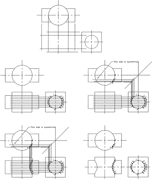
Figure 5-79
- Define points on the edge of the smaller circle. In this example, 17 points were defined.
- Extend the horizontal centerline of the smaller circle in the side view into the area of the front view. Use Draw, Offset, and add six lines parallel to the horizontal centerline in the side view. Label the intersection of the horizontal lines with the edge of the smaller circle as shown.
- Project points 5, 6, 7, 8, 9, and 10 into the top view. Use Draw, Line along with Osnap Intersection to draw vertical lines from the side view so that they intersect the 45° miter line. Then, project the intersections on the miter line into the top view by using horizontal lines. Label the points as shown.
- Project points 5, 6, 7, 8, 9, and 10 from the top view into the area of the front view so that they intersect the horizontal lines from the side view. Label the points as shown. Use Draw, Polyline, Edit Polyline, and Fit to draw the curve that represents the intersection.
- Add the lines needed to complete the front view, remove all excess lines, and save the drawing if desired.
5-33 Sample Problem SP5-11
Figure 5-80 shows the top and right-side views of a triangular-shaped piece intersecting a hexagonal-shaped piece. What is the shape of the front view?

Figure 5-80
Figure 5-81 shows the solution obtained by projecting lines from the two given views into the front view and shows an enlargement of the intersecting surfaces. Using a straightedge, verify the location of each labeled point by projecting horizontal lines from the front view and vertical lines from the top view into the front view.

Figure 5-81
5-34 Sample Problem SP5-12
Given the side and top views of a circle intersecting a cone, as shown in Figure 5-82, draw the front view.

Figure 5-82
As in the previous sample problems, the problem is solved by defining intersection points in the given two views and then projecting them into the front view. The cone, however, presents a unique problem because it is both round and tapered. There are few edge lines to work with.
The solution requires that there be a more precise definition of the cone’s surface than is presented by the circle and centerlines in the top view and the profile front view.
- Figure 5-83, step 1, shows how points 1 and 3, located on the vertical centerline of the cylinder, are projected from the side view to the front view and then to the top view. The vertical centerline is aligned with the right-side profile line of the cone so that it can be used for projection.

Figure 5-83
This is not true for points 2 and 4, located on the horizontal centerline in the side view. Currently, the location of points 2 and 4 is unknown in both the front and top views, so projection lines cannot be drawn. The location of points 2 and 4 can be determined in the front and top views.
- Extend the horizontal centerline in the side view so that it intersects the edge lines of the cone. Use Osnap Intersection, with Ortho on, and project the intersection of the extended horizontal centerline and the cone’s edge line so that it intersects the vertical centerline in the top view. Draw a circle in the top view, using the distance between the center point of the cone and the intersection of the vertical centerline and the projection line as the radius.
The circle in the top view represents a slice of the cone located at exactly the same height as points 2 and 4. Points 2 and 4 must be located somewhere in the slice.
- Project points 2 and 4 into the top view from the side view so that the projection line intersects the circular slice drawn in step 2. Label the intersections 2 and 4.
- Project the locations of points 2 and 4 in the top view into the front view, using a vertical line. Project the locations of the points from the side view into the front view, using a horizontal line. The intersection of the vertical and horizontal projection lines defines the locations of points 2 and 4 in the front view.
- Expand the procedure explained in steps 2 and 3 by drawing a series of horizontal projection lines between the front and side views, as shown. Use Draw for the first line and Offset for the other lines. The location of these additional lines is random.
Use Osnap Intersection, with Ortho on, to project the intersections of the horizontal lines with the cone’s edge lines in the top view.
- Draw circles, using the distance between the cone’s center point and the projection lines’ intersections with the vertical centerline as radii. Use Osnap Intersection to locate the circles’ center point and radii distances.
- Use Draw, Polyline, Edit Polyline, and Fit to draw the required curves in the top and front views. Use Osnap Intersection to ensure accurate curve point locations. The Move option located on the Edit Polyline command options line can be used to move vertex points on the curves to make them appear smoother and more continuous.
- Trim and erase all excess lines, and save the drawing if desired.
5-35 Designing by Modifying an Existing Part
Many beginning design assignments require that an existing part be modified to meet a new set of requirements. Designers must therefore create something different from the original drawing. This ability to look beyond the drawing is an important design skill.
Figure 5-84 shows a dimensioned part, and Figure 5-85 shows the three orthographic views of the part. The part is to be redesigned as follows:

Figure 5-84

Figure 5-85
- Replace the two ø7.5 holes with ø10 holes.
- Remove the R20 cutout.
- Modify the horizontal portion of the part so that its overall length is 45 millimeters; make the entire part symmetrical about its 90° axis.
- Round the four external and four internal corners, using a 10-millimeter radius.
Figure 5-86 shows the resulting three orthographic views.

Figure 5-86
5-36 Drawing Standards
There are two sets of standards used to define the projection and placement of orthographic views: the American National Standards Institute (ANSI), and the International Organization for Standardization (ISO). The ANSI calls for orthographic views to be created using third-angle projection and is the accepted method for use in the United States. See the American Society of Mechanical Engineers publication ASME Y14.3-2003. Some countries, other than the United States, use first-angle projection. See ISO publication 128-30.
This chapter has presented orthographic views using third-angle projections as defined by ANSI. However, there is so much international commerce happening today that you should be able to work in both conventions as you should be able to work in both inches and millimeters.
Figure 5-87 shows a three-dimensional model and three orthographic views created using third angle projection and three orthographic views created using first-angle projection. Note the differences and similarities. The front view in both projections is the same. The top views are the same but are in different locations. The third-angle projection presents a right-side view, while the first-angle projection presents a left-side view.

Figure 5-87
Figure 5-88 shows the drawing symbols for first- and third-angle projections. These symbols can be added to a drawing to help the reader understand which type of projection is being used. These symbols were included in the projections presented in Figure 5-87.

Figure 5-88
5-37 Third- and First-Angle Projections
Figure 5-89 shows an object with a front orthographic view and two side orthographic views: one created using third-angle projection and the other created using first-angle projection. For third-angle projections, the orthographic view is projected on a plane located between the viewer’s position and the object. For first-angle projections, the orthographic view is projected on a plane located beyond the object. The front and top views for third- and first-angle projections appear the same, but they are located in a different position relative to the front view.

Figure 5-89
The side orthographic views are different for third- and first-angle projections. Third angle projections use a right-side view located to the right of the object. First-angle projections use a left-side view located to the right of the object. Figures 5-90 and 5-91 show the two different side-view projections for the same object. For third-angle projection, the viewer is located on the right side of the object and creates the side orthographic view on a plane located between the view position and the object. The viewer looks directly at the object. For first-angle projection, the viewer is located on the left side of the object and creates the side orthographic view on a plane located beyond the object. The viewer looks through the object.

Figure 5-90

Figure 5-91
To help understand the difference between side-view orientations for third- and first-angle projections, locate your right hand with the heel facing down and the thumb facing up. Rotate your hand so that the palm is facing up—this is the third-angle projection orientation. Return to the thumb up position. Rotate you hand so that the palm is down—this is the first-angle view orientation.
5-38 Exercise Problems
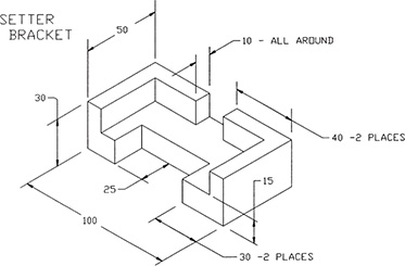
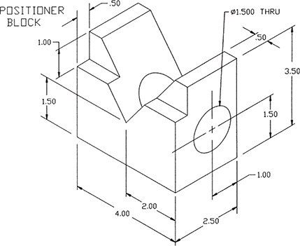
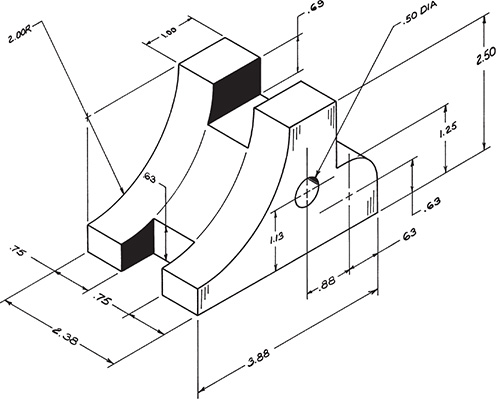
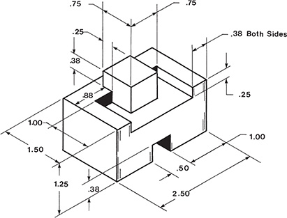
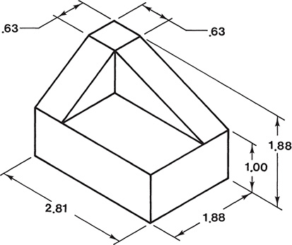
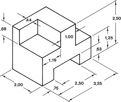
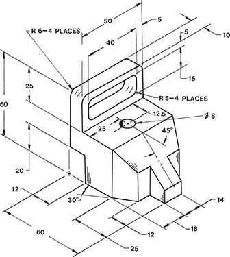
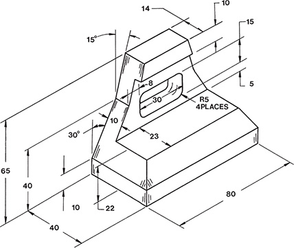
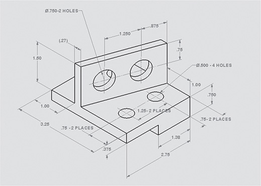
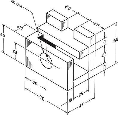
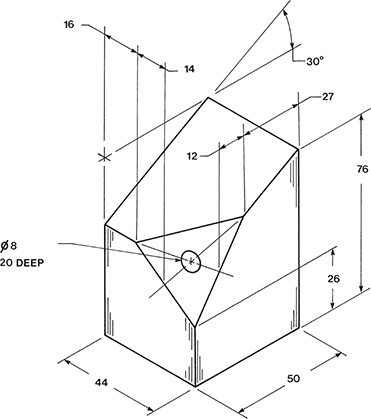
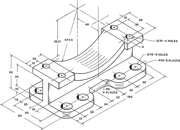
Draw a front, top, and right-side orthographic view of each of the objects in Exercise Problems EX5-1 through EX5-94. Do not include dimensions.
EX5-1 Inches

EX5-2 Millimeters

EX5-3 Millimeters

EX5-4 Inches

EX5-5 Millimeters

EX5-6 Millimeters

EX5-7 Millimeters
EX5-8 Millimeters

EX5-9 Inches

EX5-10 Millimeters

EX5-11 Millimeters

EX5-12 Inches

EX5-13 Millimeters

EX5-14 Millimeters

EX5-15 Millimeters

EX5-16 Millimeters

EX5-17 Millimeters

EX5-18 Millimeters

EX5-19 Millimeters

EX5-20 Millimeters

EX5-21 Inches

EX5-22 Millimeters

EX5-23 Millimeters

EX5-24 Inches
EX5-25 Millimeters

EX5-26 Millimeters

EX5-27 Millimeters

EX5-28 Millimeters

EX5-29 Millimeters

EX5-30 Millimeters

EX5-31 Inches
EX5-32 Millimeters

EX5-33 Inches

EX5-34 Millimeters

EX5-35 Millimeters

EX5-36 Inches

EX5-37 Millimeters

EX5-38 Millimeters

EX5-39 Millimeters

EX5-40 Millimeters

EX5-41 Inches

EX5-42 Inches
EX5-43 Millimeters

EX5-44 Millimeters

EX5-45 Millimeters

EX5-46 Millimeters

EX5-47 Inches
EX5-48 Inches
EX5-49 Millimeters

EX5-50 Inches

EX5-51 Inches

EX5-52 Millimeters

EX5-53 Inches

EX5-54 Millimeters
EX5-55 Millimeters

EX5-56 Millimeters

EX5-57 Millimeters
EX5-58 Millimeters

EX5-59 Millimeters

EX5-60 Inches

EX5-61 Millimeters

EX5-62 Millimeters

EX5-63 Millimeters

EX5-64 Millimeters

EX5-65 Millimeters

EX5-66 Millimeters

EX5-67 Millimeters

EX5-68 Millimeters

EX5-69 Millimeters

EX5-70 Millimeters

EX5-71 Millimeters

EX5-72 Millimeters

EX5-73 Millimeters

EX5-74 Inches

EX5-75 Inches
EX5-76 Millimeters
EX5-77 Millimeters

EX5-78 Millimeters

EX5-79 Millimeters

EX5-80 Millimeters

EX5-81 Millimeters

EX5-82 Millimeters

EX5-83 Millimeters

EX5-84 Inches

EX5-85 Millimeters

EX5-86 Millimeters

EX5-87 Inches

EX5-88 Millimeters
EX5-89 Millimeters

EX5-90 Millimeters

EX5-91 Millimeters

EX5-92 Millimeters

EX5-93 Millimeters

EX5-94 Millimeters
For Exercises EX5-95 through EX5-100:
Sketch the given orthographic views, and add the top view so that the final sketch includes a front, top, and right-side view.
Prepare a three-dimensional sketch of the object.
EX5-95

EX5-96

EX5-97

EX5-98

EX5-99

EX5-100

For Exercise Problems EX5-101 through EX5-128:
Redraw the given views, and draw the third view.
Prepare a three-dimensional sketch of the object.
EX5-101 Inches

EX5-102 Inches

EX5-103 Inches

EX5-104 Inches

EX5-105 Inches

EX5-106 Inches

EX5-107 Inches

EX5-108 Inches

EX5-109 Inches

EX5-110 Inches

EX5-111 Inches

EX5-112 Inches

Each exercise on this page is presented on a 10 × 10-mm grid.
EX5-113

EX5-114

EX5-115

EX5-116

Each exercise on this page is presented on a .50˝ × .50˝ grid.
EX5-117

EX5-118

EX5-119

EX5-120

Each exercise on this page is presented on a 0.50˝ × 0.50˝ grid.
EX5-121

EX5-122

EX5-123

EX5-124

Each exercise on this page is presented on a 10 × 10-mm grid.
EX5-125

EX5-126

EX5-127

EX5-128
Draw the complete front, top, and side views of the two intersecting objects given in Exercise Problems EX5-129 through EX5-134 on the basis of the given complete and partially complete orthographic views.
EX5-129 Millimeters

EX5-130 Millimeters

EX5-131 Inches

EX5-132 Inches

EX5-133 Millimeters

EX5-134 Millimeters

Draw the front, top, and side orthographic views of the objects given in Exercise Problems EX5-135 through EX5-138 on the basis of the partially complete isometric drawings.
EX5-135 Millimeters

EX5-136 Millimeters

EX5-137 Inches

EX5-138 INCHES (SCALE: 5=1)

Redesign the existing objects as indicated in Exercise Problems EX5-139 through EX5-142, and then prepare a front, top, and right-side view of the object.
EX5-139 Millimeters

EX5-140 Millimeters

EX5-141 Millimeters

EX5-142 Millimeters

Given the following orthographic views, create a 3D model of the object:
EX5-143 Millimeters

EX5-144 Millimeters

Exercise problems are presented using first-angle projection and ISO conventions.
Create a solid model from the given orthographic views.
Draw front, top, and right-side orthographic views of the objects using third-angle projection and ANSI conventions.
EX5-145

EX5-146

EX5-147

EX5-148

EX5-149
