
Chapter 5: Advanced Application Architecture Modeling
To develop or procure a business application, it is not sufficient to stay at a conceptual level of detail. The more detail that you provide, the easier it becomes for developers to build or customize a solution according to your requirements. However, as an enterprise architect, you are not expected to provide details for the developers because that is the job of a solution architect. Your job, in fact, is to provide details for the solution architects themselves to have the best understanding of the business requirements and direct the application, data, and technology architects on what will be delivered and how.
In this chapter, we will describe the Tracking App application from various perspectives. The two types of perspectives you can choose to describe an application are the structure and the behavior, and this is what we will be learning about in this chapter. We will be covering the following topics:
- Determining what diagrams to produce
- Describing application behavior
- Describing application structure
There are more diagrams to explore in this chapter compared to previous chapters, so get ready for a faster pace and more condensed information. You are not new to Sparx anymore, so you should be just fine.
Technical requirements
This chapter does not have any additional technical requirements other than having Sparx Systems Enterprise Architect (EA). If you do not have a licensed copy, you can download a fully functional 30-day trial version from the Sparx Systems website (https://sparxsystems.com/products/ea/trial/request.html).
We will continue adding the content of this chapter in the same EA repository that we built in Chapter 3, Kick-Starting Your Enterprise Architecture Repository, and Chapter 4, Maintaining Quality and Consistency in the Repository. If you have not read these two chapters, we strongly advise you to read them first and then come back to read this chapter, as many step-by-step instructions that have been detailed in these two chapters have been skipped or summarized in this chapter to avoid repetitive information here and there.
If you want to practice while reading, you can download the repository file of Chapter 4,Maintaining Quality and Consistency in the Repository, from GitHub at https://github.com/PacktPublishing/Practical-Model-Driven-Enterprise-Architecture/blob/main/Chapter04/EA%20Repository.eapx instead of starting from scratch. Some of the steps in this chapter depend on elements that have already been created in the repository, so it is better to not start this chapter with an empty repository. However, if you want to download the resultant repository of this chapter, which contains all the diagrams that will be created in it, you can do so by following this link: https://github.com/PacktPublishing/Practical-Model-Driven-Enterprise-Architecture/blob/main/Chapter05/EA%20Repository.eapx.
We will use the following ArchiMate® 3.1 specification chapters to guide our development:
- Chapter 5, Relationships (https://pubs.opengroup.org/architecture/archimate3-doc/chap05.html#_Toc10045310)
- Chapter 9, Application Layer (https://pubs.opengroup.org/architecture/archimate3-doc/chap09.html#_Toc10045389)
- Chapter 12, Relationships Between Core Layers (https://pubs.opengroup.org/architecture/archimate3-doc/chap12.html#_Toc10045440)
The metamodel diagrams in the aforementioned references will be used throughout this chapter, so we highly advise you to print them and keep them in reach for maximum benefit.
Determining what diagrams to produce
Before we get into the various types of diagrams that you can produce, we need to introduce a couple of concepts, the concepts of the view and the viewpoint. If you're involved in a project where a single diagram is supposed to explain everything you need to know about a system or application, then drop the diagram, turn around, and run. Such a diagram cannot exist.
Some diagrams claim to do so, but they are usually far too big, far too busy, and don't convey a quarter of what is needed. They usually follow no standard and are created by those with little or no modeling experience. They make little sense except to their creator. The biggest problem with such diagrams is that they tend to convey a single set of concerns, those of the creator.
But please be careful, and be kind! These folks may have expended a lot of time and effort. They are often very knowledgeable and very proud of their work. The last thing you want to do is to create enemies on the project. Instead, praise their work and bring them into the fold of architecture professionals. Hand them a copy of this book. Also, there is often some useful information in these diagrams – information that you can glean for more meaningful models.
Understanding the view
So, how do you know what diagrams to create? Any given diagram or set of diagrams can be considered a view of the system in question. Every system has many stakeholders with their own view of the system, so you may have to develop a different number of views for each stakeholder. Each view may convey a slightly different set of information. Hence, which views should be created depends on the stakeholders and their concerns.
You may need to create many views of the system to address the concerns of all the stakeholders. This implies that you need to know who the stakeholders are, and what their concerns are. Often, you can infer a great deal about their concerns based on their position in the organization. For example, the controller, accounting manager, and bookkeepers are more likely to be interested in the financial aspects of the system. They will want to know about financial reports created by the system as well as financial records created or manipulated by the system.
In contrast, computer operators want to know about things such as backup, restore cycles, exceptions, batch processing, or anything that may affect them. Developers want to know what components make up the system and each of their roles, what services are expected, and so on. Views can mainly be categorized into two main categories, structural and behavioral, as we will see next.
Structural and behavioral views
We will look at the types of diagrams you can create, but let's first talk about the difference between structure and behavior views. We will use the human body as an analogy to clarify the difference. The way that we react when we hear sounds, for example, describes behavior. We may react to music in one way and to conversations in a different way. We react to loud sounds of danger in yet another different way.
Our bodies receive sound waves from the environment through our ears. Our brains translate that information and react by behaving accordingly. In fact, the process of receiving sound and transmitting it to our brain is also part of the body's hearing behavior. To understand the hearing function, we need to understand the parts of the body that play a role in hearing and how they are related. The ear, ear drum, ear canal, cochlea, cochlear nerve, and the brain all play a role in hearing. How they are related to each other and their individual roles comprise the structure of our hearing ability.
If we were to describe hearing ability in a set of models, we would likely describe the overall structure of the body at a high level to identify where the ear is located, and then, in a separate diagram, we would describe the components of the ear. These two views would describe the structure of our hearing ability. To describe the process of hearing, we would need yet another set of diagrams.
An overall diagram would describe the overall path of a soundwave as it enters the ear canal and gets translated into an electric signal that enters the brain. A lower-level set of diagrams might be needed to describe the process each component of the ear uses to accomplish its individual role. To completely understand how we hear, we need both the structural and the behavioral diagrams. Most importantly, we need to know what our target audience is interested in seeing in our diagrams, and this is where viewpoints play an important role.
Getting to know the viewpoint
Describing the hearing system for a sixth-grade student is different than describing it for a family doctor who specializes in the Ear, Nose, and Throat (ENT). The details that you put in both books will be completely different even though they both talk about the same system. They are both right, but each addresses a different audience and serves a different purpose. This is where viewpoints come in – to tell us what each stakeholder is interested in.
If you're in an organization and working with a team of architects, it may be helpful for you to create what is known as a viewpoint. This is simply a specification for the view. It describes what type of diagrams you will create, what notation you will use, what stakeholders you are targeting, and what concerns you are addressing. Basically, you are telling the reader what they should be getting from the view. The concepts of the view and viewpoint are specified in TOGAF® 9.2 (https://pubs.opengroup.org/architecture/togaf9-doc/arch/chap31.html).
There are also several predefined viewpoints available with the standard. The specifics of how to create a viewpoint are beyond the scope of this book. We encourage you to look at the standard and determine for yourself the degree to which you need to specify a viewpoint for your views. Suffice to say that considering the readers (stakeholders) of your diagrams and their concerns is probably the most important thing you need to ponder.
Once you know what your stakeholders are interested in seeing, it is time to produce some diagrams describing the Tracking App application component, and we will start by describing the behavior of the application.
Describing application behavior
Application behavior describes the functions, processes, and services an application delivers. Behavior includes answers to questions such as what happens, in what order, what is used, and what the result is. Behavior also describes what functionality is made available to other components as services, and what happens when an unexpected event occurs. This information can be modeled and provided as a way of documenting the application, so application stakeholders can visualize the application behavior and make early decisions regarding it. This is what we will learn about in this section as we answer the following questions:
- What are application services, who needs to know about them, and how do we model them?
- What are application processes, who needs to know about them, how are they related to the application services, and how do we model those processes?
- What are application functions, how are they related to services and processes, and how do we model them?
- What are application events, and how do we model them?
Keep in mind that the elements mentioned in the preceding list – services, processes, functions, and events – all represent behavior. In some cases, they can overlap, which confuses many architects and causes continuous disagreements.
What one architect perceives as a function might be perceived as a process by another architect and as a service by a third. They could all be right, but because of their different experiences and the different stakeholders they serve, they do not necessarily agree. We will explain the differences with examples and learn how to build the right models that convey the right level of detail. Let's start with application services.
Introducing application services
According to ArchiMate® 3.1, an application service "represents an explicitly defined exposed application behavior" (https://pubs.opengroup.org/architecture/archimate3-doc/chap09.html#_Toc10045401).
This means that application services are clearly visible to the external enterprise, so they are what the enterprise sees and knows about a specific application. When looking at an application service catalog, you are looking from the external service consumer perspective.
ArchiMate® provides two notations to model application services – rectangular and borderless. We will use both notations in some different diagrams, but in the end, it is a matter of preference:

Figure 5.1 – ArchiMate®'s Application Service notations
Knowing what services an application component provides is different than knowing how to access and consume the services. Thus, it is very important to understand that application services describe the behavior of an application component, not its structure. The part of the application that you use to consume a service, such as exchanging data or performing an action, is called the application interface. We will talk about it in more detail in Introducing application interfaces in the next section of this chapter. Interfaces are the structures that provide access to services, so they are the exposed tangible part of a component. They are the entry points that allow consumers to use services.
Another very important thing that you need to understand is the difference between application services and application components. The line between the two is very thin, but it is very clear once you see it. Architects coming from a Service-Oriented Architecture (SOA) background might call the entire component a service or web service. Web services, from ArchiMate®'s point of view, are application components, not application services, because they encapsulate functionality, and are modular and replaceable.
For example, if you have a web service that prints mailing labels, then ArchiMate® considers it an application component that provides the printing mailing labels service. So, there are two types of architectural elements that we can use to model our web service example. The application component is the tangible and deployable part, while the application service is the descriptive part. Please remember this essential difference and remember that it is a quite common confusion because of how other industry standards define services. We are following ArchiMate®'s definitions in this book.
A single component can provide multiple services, so it depends on how the component is designed and constructed. Some components can provide hundreds of services, while some microservice components may provide only a single service. The number of provided services does not affect the classification of what a service and a component are. A single service can be provided by multiple components as well. For example, you may have multiple products from multiple vendors, each of which prints mailing labels. They may differ in how the service is performed and provided, but they all provide the same service. Also, multiple components may work together to provide a single service.
Additionally, we need to differentiate between application services, technology services, and business services. They obviously belong to different architecture layers, as their names imply, but as you categorize the services in your enterprise, it may become difficult to decide which service belongs to which layer. Business services are the services that your business provides to its customers regardless of whether they are done through a website, a call center, or a sales showroom. A grocery store, for example, provides a retail grocery sales business service whether you walk in, use their online virtual store, or order by phone. We will talk in more detail about business services in Chapter 8, Business Architecture Models.
Technology services are usually the services that are provided to your business at the technology infrastructure level, such as networking, storage, protection, computing, and many other services. Services that are available on Amazon Web Services (AWS) or Microsoft Azure are great examples of technology services, as they are not related to any specific business type. We will talk in more detail about technology services in Chapter 6, Modeling in the Technology Layer.
Finally, application services are software services just like technology services, but they encapsulate business-specific logic in them, so they are not as business-neutral as technology services. They also encapsulate technology, so they are not as technology-neutral as business services. They are in between the two. They apply technology to help solve business problems, thus the name application. Order processing is an example of an application service that automates processing orders for a specific retail business, and to do that, it uses business logic and rules that are specific to that business. All business types process their orders differently, so each can implement the order processing application service differently.
We need to look at some real-world examples to clarify all these points about application services, but let's first define the focused metamodel that we will use to guide the development of our models.
Defining the application service focused metamodel
Focused metamodels are models that guide the development of a single specific element at once. Each focused metamodel will have a single focus element that describes every possible connection between it and other enterprise elements to which it is allowed to connect. The focused metamodels are simply an element-by-element translation of the ArchiMate® 3.1 metamodels. If you were to combine all these focused metamodels, you would get the complete metamodel of all ArchiMate® 3.1 elements. It would be a very complex diagram, with many intersecting and overlapping connectors. It would be difficult to read, so we will not build it. Just remember that it can be built.
In Chapter 4, Maintaining Quality and Consistency in the Repository, we developed a focused metamodel for the application component element, and we saw how the application component was at the center (the focus), while other elements surrounded it. We will use that focused metamodel whenever we need to build a model describing an application component.
In this section, we will develop the focused metamodel for the application service element, and we will use it whenever we build a model describing an application service. The application service element will be the focus this time, while other enterprise elements including the application component will surround the application service element. The application component that was the focus in Figure 4.9 of Chapter 4, Maintaining Quality and Consistency in the Repository, will appear in the application service focused metamodel as a secondary element, and the application service element that appeared as a secondary element in that diagram will appear as the focused element in this focused metamodel. However, it is very important to keep in mind that they are the same elements, regardless of which one is the focus and which one is not.
Think about it as if you are taking pictures of your children on their graduation day. Most likely, you will focus on them in all the photos you take, while every other student in the background will be secondary person. Your children will also appear in other parents' pictures, but they will be a secondary persons in their pictures because their child will be the person focused on. In both cases, your child is still the same person, and if the school wanted to count how many students appeared in all the pictures taken by all parents, every student would be counted once, regardless of how many pictures they appeared in.
We will use the ArchiMate® 3.1 standard to guide our focused metamodel development, and we will translate our understanding and interpretation of it into an easier-to-understand reference for every architect that will contribute to the enterprise architecture repository.
Interpreting the standard
The following list is our interpretation of the diagrams and definitions in the three reference chapters that we indicated in the Technical requirements section:
- An application service serves an application's internal behavior element (such as an application function, an application process, or an application interaction).
- An application service can be realized by an application's internal behavior element.
- An application service serves an application's internal active structure element (such as an application component or an application collaboration).
- By default, every enterprise element can be composed/decomposed into elements of its type, so an application service can compose/decompose other application services.
- An application service can trigger, be triggered, or flow to another application service.
- An application service can trigger, be triggered, or flow to an application event.
- An application interface can be assigned to an application service.
- An application service can access a data object.
- An application service realizes a business service.
- An application service serves a business internal active structure element (a business role, a business actor, or a business collaboration).
- An application service serves a business internal behavior element (business process, business function, and business interaction).
- An application service is realized by a technology service.
- An application service serves a technology internal active structure element (a node or a technology collaboration).
- An application service serves a technology internal behavior element (a technology process, a technology function, or a technology interaction).
As you can see, the aforementioned list of statements about the application service metamodel is a bit long, which is expected for an element that is externally exposed to other enterprise elements. As a result, we expect the resulting diagram to be large and contain many elements, so just keep that in mind. We have sufficient information to start building the application service-focused metamodel, so let's get ready.
Building the focused metamodel
The application service will obviously be the focus element in the application service-focused metamodel. But before you drag a new application service element from the toolbox to the diagram, remember that our repository is no longer brand new, and we might have already created that element.
If you revisit Figure 4.9 in the previous chapter, you will see that we have already created an application service element in that diagram, which means that it already exists in the repository, and we must reuse it in this and other metamodel diagrams. Follow these steps to learn how:
- From the project browser, open the Metamodels package, create a new diagram in it, and name it Application Service Focused Metamodel.
- Optionally, choose to show diagram details (the blue label at the top-left corner of the diagram). Also optionally, change the diagram's theme to High Contrast White to remain consistent with what we are building.
- Find the application service element in the metamodel package and place it on the diagram. Sparx proceeds every ArchiMate element in the repository with a stereotype that follows this pattern – <<ArchiMate_element type>>element Name. So, the full name of the element that you are looking for is <<ArchiMate_ApplicationService>>Application Service.
- When you place an existing element on a diagram, Sparx may display a dialog box asking whether you want to reuse the item as a link or a child from the Drop as drop-down list:
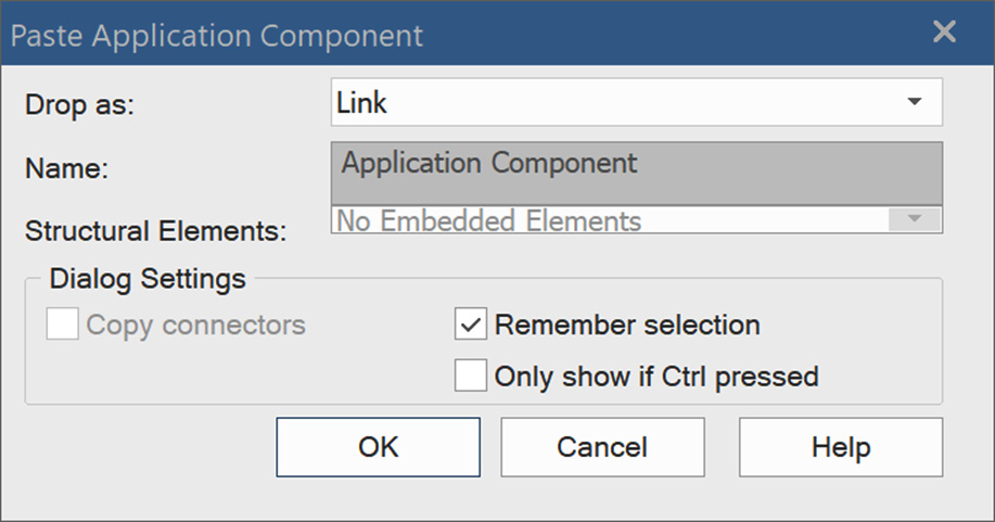
Figure 5.2 – The Paste Application Component dialog box
This dialog box will not be displayed by default for every element type, so to force it to appear, hold the Ctrl key while dragging.
- Select Link because this tells Sparx that we are reusing the same element on a new diagram. Choosing Child means that the copied element is a specialized child of the existing element, a technique that is particularly useful when modeling classes in the Unified Modeling Language.
- Leave the remaining options as they are and click OK.
The next step is to add the related elements as interpreted by the ArchiMate® specification. Remember that some of these elements already exist in the Metamodels package, so you must check to see whether the elements to be added to the diagram already exist or need to be created.
- Find the following elements in the Metamodels package and place them on the diagram: application event, application process, application function, application interaction, application component, application collaboration, application interface, data object, business service, and technology service.
Once you place the application component element on the diagram, Sparx displays all the relationships that already exist between the application component and the other elements. The same thing will happen every time you place an existing element on the diagram, and all the relationships between that element and the other visible elements on the diagram will be shown too.
Seeing these relationships in other focused metamodels and diagrams is useful, as we can understand all the possible relationships to and from the elements. However, our focus element, for now, is the application service, so to keep it focused, the application component relationships are irrelevant to its context. Remember that the main objective of creating the focused metamodels is to focus on a single element at a time, so we need to hide the needless relationships.
- To hide a relationship from a diagram, right-click on the desired relationship and select Visibility > Hide Connector. Alternatively, to hide a relationship, highlight it by clicking on it, press the Delete button, and a dialog box like the one shown in the following screenshot will pop up, asking you whether you want to permanently delete the relationship connector or just hide it in this diagram. Since we only want to hide the relationship from this diagram, keep the Hide the connector choice selection, and click the OK button:

Figure 5.3 – The Remove Connector popup
- Repeat the previous steps for all the relationships that do not connect to or from the application service element because, in this focused metamodel diagram, we only need to show the application service relationships.
Important Note
Another useful way to show or hide a long list of relationships in a diagram is to click Layout > Diagram > Appearance > Set Visible Relationships. Sparx will show you a pop-up window containing a list of all the relationships that exist between the elements on the diagram. Check the box next to the relationships that you want to show and uncheck them for the ones that you want to hide.
There are still elements that have been identified in the interpretation list, but they do not exist in the Metamodels package because we have not created them in the repository yet. For these elements, they must be created from Toolbox, which will require activating the business toolbox and the technology toolbox to get the desired business and technology elements respectively. Refer to the Adding Actors subsection, in the Adding elements to the diagram section, from Chapter 3, Kick Starting Your Enterprise Architecture Repository, to see how to change the toolbox, if you forgot how.
- From the business toolbox, add the following elements to the diagram: business role, business actor, business collaboration, business process, business function, and business interaction.
- From the technology toolbox, add the following elements to the diagram: node, technology collaboration, technology process, technology function, and technology interaction.
- Optionally, style all application architecture elements using the saved App Arch style, all the business architecture elements using the saved Biz Arch style, and all the technology architecture elements using the Tech Arch style.
- Optionally too, change the appearance of all the elements to the borderless notation while keeping the application service element with the rectangular notation.
- Rearrange the elements on the diagram to have the application service in the middle, bigger than the other elements, with a thicker border, and surrounded by all the other elements.
The last thing that we need to do to complete this focused metamodel is to create the relationships that connect the application service element with other elements, as we have defined in the interpretation. We already have the serves relationship between the application service and the application component, so follow the next steps to add the remaining relationships.
- Create a triggers relationship from the application service element to itself to indicate that an application service can be triggered or triggered by another application service.
- Create a serves relationship from the application service to the application process element.
Remember that these two elements exist on another diagram, which is the application component-focused metamodel. If you open that diagram now, you will see that this newly created relationship is also visible there, which is not what we want. If we add all the relationships that we have on our interpreted list, we will turn the application component-focused metamodel diagram into a spaghetti diagram, with dozens of relationships going in every direction. Therefore, we must ensure that any new relationship that we create on this diagram will not be visible on other diagrams.
- Right-click on the relationship connector and choose Visibility > Hide Connector in Other Diagrams. The Set Connector Visibility pop-up window will appear with a list of all the other diagrams that this relationship will appear on:

Figure 5.4 – The Set Connector Visibility popup
Important Note
Your list may contain more or fewer diagrams in it, based on the number of diagrams that contain the selected relationship.
Remember to keep the relationship visible on the diagrams that it needs to be visible on. If you hide all the relationships in all the other diagrams, you will end up with only the active diagram showing relationships, which is not what we need to achieve.
- Repeat step 17 to step 18 for all the relationships that are identified in the interpretation list.
In some cases, even if we were careful in showing and hiding the relationships in other diagrams, we may accidentally hide a needed relationship and show an unneeded one, so we recommend you go back to older diagrams and check to make sure that they still look okay.
- Open the application component-focused metamodel diagram and make sure that all the relationships that we want to keep visible are visible, and all the relationships that we need to hide are hidden.
- Finally, make sure to save your work.
This was a difficult metamodel to create, so don't feel that you're the only one who faced difficulties in understanding it or struggled in following the steps to create it. In Chapter 4, Maintaining Quality and Consistency in the Repository, we created a relatively simply focused metamodel and provided more detailed instructions than the ones we provided here, so refer to it for more information.
Important Note
Creating metamodels in your repository is important but not essential. You can use the metamodels that are provided in this book, or you can use the standard ArchiMate® metamodels to create diagrams. Enriching your repository with diagrams is more important than enriching it with references.
By following the aforementioned steps, you will get a diagram like the following:

Figure 5.5 – The Application Service-focused metamodel
As expected, the Application Service-focused metamodel contains many elements and relationships, but congratulations – this will be a reference in your repository that you will rarely change! Barring a few cases where a new version of the ArchiMate® specification is released, you find a missing element or a mistake, or the organization that you work for has a specific need to adjust or override the standard, this diagram is ready to be printed and pinned to your workspace. You can refer to it whenever you model application services.
Use this focused metamodel to build an unlimited number of enterprise architecture models, and it will be your guide to maintaining consistency in your repository as well as adhering to the industry standard.
In the next subsection, we will show you some examples of how we can build diagrams based on the focused metamodel that we have just defined.
Modeling application services
In Chapter 3, Kick-Starting Your Enterprise Architecture Repository, we developed a model that identifies what a Tracking App is, what services it provides, and other similar information. In this subsection, we will elaborate more on the provided Vehicle Tracking service, so we will develop more models that have it as the focus element. Remember that these are just examples to convey the idea of different model types. You need to apply these examples in your work environment with actual components from your enterprise and based on the concerns of your stakeholders.
Modeling application service context
Context diagrams show an element in the context of its environment or surroundings. These diagrams apply to any element in the enterprise, as they show multiple aspects and relationships all in one place. They provide an overview, not a detailed view. You can always provide more detailed models when needed. We introduced the Tracking App to the stakeholders in Figure 3.16 of Chapter 3, Kick-Starting Your Enterprise Architecture Repository, using a context diagram. We will drill down from that diagram and provide a more detailed model just about the Vehicle Tracking application service. The purpose of this diagram is to give a more detailed overview of how this specific application service fits into its environment.
We will use the application service-focused metamodel from Figure 5.5 as a reference for developing this model and knowing what elements can relate to the application service. There are 21 different element types on this metamodel, but this does not mean that we must use all of them in our context diagram. We will use only what we need to answer the question, what is the vehicle tracking service? If you want, you can print a copy of the application service-focused metamodel, and follow these steps to create a context diagram for the Vehicle Tracking application service:
- Open the Tracking App package in the project browser.
- Right-click on the package and select Add Diagram to open the New Diagram dialog box.
- Enter Vehicle Tracking Context Diagram as a name for the diagram. Select the ArchiMate3.1 Application diagram type.
Since we already created the Vehicle Tracking application service earlier, we need to reuse it in this diagram and expand it by adding more information to its context.
- Locate the Vehicle Tracking application service in the Tracking App package and place it in the center of the new diagram.
Since this is an existing element and we are reusing it, it may also contain some of the information that we need to have in this new context diagram. Therefore, we need to check what information is available and decide what we need to reuse.
- Right-click on the Vehicle Tracking element on the diagram and select Insert Related Elements from the context menu. This will open the dialog box that is shown next:

Figure 5.6 – The Insert Related Elements dialog box
The dialog box shows all the items that are related to the selected element, which in our case is the Vehicle Tracking service. You can select or unselect the elements that you want to insert. You can also filter by Connector types or Element types and then refresh the list.
- In this diagram, we want to reuse all the related elements, so click All to select all the listed elements, and then click OK.
- The inserted elements are put on the diagram as a cascaded list, so reorganize them in a way that makes sense to you, and style them if needed. Also note that the related elements are inserted with the relationships that we created earlier in Chapter 3, Kick-Starting Your Enterprise Architecture Repository.
One important aspect of application services, in general, is that they exist to realize business services. If an application service does not realize a business service, then it is considered an extra or even a useless service that an application has but the business does not use. The beauty of enterprise architecture is that it shows you all these essential connections. In this context diagram, we need to show the business service or services that are realized by the Vehicle Tracking application service.
Business services will be covered in detail in Chapter 8, Business Architecture Models. For now, we need you to understand the difference between business services and application services. Business services are neutral from any application or technology implementation. They exist with or without computers. Automation and technologies make them more efficient for sure, but the existence of business services is an essential part of performing business strategic missions themselves. For a trading company, tracking vehicles' locations is not a service that they need to provide, but goods transportation is. Therefore, we can say that vehicle tracking is an application service that realizes the goods transportation business service and makes it more efficient.
Furthermore, the ABC Trading company may have an Enterprise Resource Planning (ERP) solution that provides a service for goods transportation. This will be the Goods Transportation application service realizing the Goods Transportation business service. Even though the two services can have the same name and are tightly related to each other, it is very important to differentiate them as two architectural elements when they are defined in the repository.
Having said that, we need to add this realization to the model in the next step.
- Change Toolbox to ArchiMate 3.1 > Business, pick the Business Service element, drop it on the diagram, and rename it Goods Transportation. Style the business service element if you want.
- Create a realizes relationship from the application service to the business service.
For an application service to work, it needs data and a set of processes to manipulate it. Let's add these two elements to the diagram. We know that this service will provide the device location data to consumers, so we need to add it to our diagram.
- Find the Device Location Data object in the Tracking App package and drop it on the diagram. Style it if needed.
- Create an accesses relationship from the application service to the data object.
Now, we need to define the process or the processes for manipulating the device location data. We will talk in detail about application processes later in this section, so let's keep things simple for now and add a new application process to the diagram.
- Change to the ArchiMate 3.1 Application toolbox if it is not already active.
- Take a new application process element, place it on the diagram, and rename it to Manipulate Device Location Data.
- Create a realizes relationship from the application process to the application service.
Finally, we need to indicate how this application service will be provided. In other words, what application interfaces will provide the service? Services are provided to users through User Interfaces (UIs) and to applications through Application Programming Interfaces (APIs). An application service can be provided by many application interfaces, and an application interface can provide many application services. We will talk in detail about application interfaces in the next section of this chapter, but for now, follow the remaining steps.
- Find the application interface element in the toolbox and use it to add six new application interfaces to the diagram.
- Name the application interfaces Android UI, iOS UI, Command Line UI, Web UI, SOAP API, and REST API.
- Create assigned to relationships, going from the application interfaces to the application service.
Important Note
Always remember that our references for developing models (or diagrams) are metamodels. Our reference metamodel indicates that the relationship between an application service and a data object, for example, is of the accesses type, so we must adhere to this and avoid creating any different relationships that are not part of the standards.
The diagram has enough information by now, but this does not mean that we cannot add any additional elements to it. We can always come back and add more elements as we discover them. We will keep learning, and our stakeholders' requirements will keep evolving too. The diagrams for your actual work may end up bigger, more complicated, and with more elements. If they become too busy, then it is an indicator that you need to split the information over multiple smaller diagrams. Refer to the modeling guidelines that we provided in Chapter 4, Maintaining Quality and Consistency in the Repository.
For the sake of the example, we will stop at this amount of information. The Vehicle Tracking context diagram should now look like the following:

Figure 5.7 – The Vehicle Tracking application service context diagram
This artifact may look very different from what you were expecting for an application service model. But this way, you are presenting the application service at a conceptual level that makes it perfect for management to understand. Always keep the targeted reader in mind.
Even though it represents an application-level artifact, it is void of implementation detail, which is necessary for management-level stakeholders. You can add a deeper level of detail in a different diagram if you choose to and have the experience. You can also hand this conceptual design to another architect who can provide that detail. Remember that your role as an enterprise architect does not mean that you must build everything but instead make sure that the enterprise elements and stakeholders are connected and communicating properly. A diagram such as the one shown in Figure 5.7 will help to ease these connections.
The next subsection will provide you with another example of a management-level artifact that you can add to your enterprise architecture repository.
Modeling an application services catalog
Context diagrams are useful, but they show one element at a time. What if you want to show multiple application services in one diagram? The application services catalog is an artifact that shows a list of application service elements. The size of the list varies based on its scope.
You can have a catalog of all the application services that are provided by a single application component. Another catalog might contain a list of all the application services in the enterprise. A third catalog might contain a list of all the application services that a given business actor is looking for in a targeted (or to-be targeted) application, and so on.
The following diagram is an example of an enterprise application services catalog. Depending on its scope, your actual catalog will most likely be larger:

Figure 5.8 – An enterprise application services catalog example
Note that in Figure 5.8, we have only used one of the relationships that were identified in the application service-focused metamodel, which is self-composition. Services can be composed of smaller services, which in turn can be composed of yet smaller services. If you are modeling a set of services that already exist in the enterprise, it is a good practice to keep them all together in the same package structure.
This makes it easier when you need to reference the service in future models. The services package may contain sub-packages to keep the services organized. If, on the other hand, you are working on a specific project for a new application that has not yet been developed or implemented, you'll probably want to keep the services in a project-specific package. Either way, it pays to keep your repository organized. It's also a good practice to revisit the subject of repository structure from time to time. An occasional restructure is not uncommon.
Linking diagrams in Sparx
In some cases, you may have a high-level diagram that drills down to one or more detailed diagrams. We have Figure 5.8, which lists all application services provided in the enterprise. We also have Figure 5.7, which details one of these application services. Being able to link the two diagrams will provide users of the enterprise architecture repository the ability to navigate from one level of detail to another, or from one element to another. This is a very powerful feature in Sparx, and by using it properly, your enterprise models can all be connected. Users will also have a better understanding of the enterprise components by navigating through models.
To link Figure 5.7 and Figure 5.8, follow these steps:
- Open the Enterprise Application Services Catalog diagram that we reviewed earlier in this section.
- Locate the Vehicle Tracking application service on the diagram. Right-click on it and select New Child Diagram > Select Composite Diagram from the context menu.
The Select Classifier dialog box will open, asking you to select the child diagram of the selected element, as follows:

Figure 5.9 – The Select Classifier dialog
If your enterprise repository becomes too large and composed of many levels of nested packages, you may find it difficult to find the desired diagram by yourself. It will be better to search for the diagram and let Sparx find it for you, as explained in the following steps.
- In the left tab of the Select Classifier dialog, click on Search, which will change the content of the dialog box to the following:

Figure 5.10 – Search for the classifier
- Type the name of the diagram that you are searching for or type a small part of it, and then click Find. This will list all the diagrams that match the search criteria.
- Select the desired diagram from the results list and click OK.
Note how the Vehicle Tracking application service has a small chain symbol at the bottom-right corner, as shown in Figure 5.11. This indicates that the element has a linked child diagram:

Figure 5.11 – The chain symbol indicates a linked diagram
Important Note
Elements modeled using the borderless notation will not show the chain symbol at the bottom-right corner of the element. Only rectangular elements will.
Double-click on the Vehicle Tracking element, and you will see how Sparx opens the linked child diagram in the diagram area. You can navigate back to the previous diagram by clicking the back arrow at the corner of the diagram tab, as shown in Figure 5.12. The back arrow replaces the standard x symbol that we usually use to close a diagram:
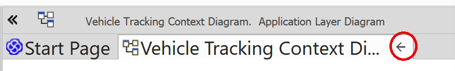
Figure 5.12 – The back arrow replacing the x symbol
Another way to know whether an element has a child diagram or not is to single-click on the element to highlight it. If the element has a linked child diagram, an eye-like symbol will appear above the top-left corner of the element, as shown here:

Figure 5.13 – The eye symbol indicates a linked child too
Clicking this eye will provide a read-only view of the child diagram in a pop-up window without opening it in the diagram area. As you can see, navigation between models is a very powerful feature. It can take you from one element to another and from one level of detail to another, just as hyperlinks work in web browsers. This is a very convenient way to help your enterprise architecture users understand more about the enterprise and how it is connected. Now, follow the same steps to link the Tracking App element to the Tracking App context diagram.
Important Note
You can link only one diagram to one element. However, you can make the same diagram a child of many other elements.
In the next subsection, we will learn about another application behavior element, which is the application process.
Introducing application processes
ArchiMate® 3.1 states that an application process "represents a sequence of application behaviors that achieves a specific result" (https://pubs.opengroup.org/architecture/archimate3-doc/chap09.html#_Toc10045399).
Application processes are internal behavior elements. They describe how to achieve a specific result by executing a set of activities in a specific sequence. Suppose, for example, that the application needs a person's age in years. It can calculate the age by following these simple steps:
- Get a person's birth date.
- Get today's date.
- Subtract the birth date from today's date and ignore the day and month in the result.
Application processes are always confused with business processes and technology processes, so we will try to highlight the main differences to avoid this confusion. They are all processes, to begin with, so they all perform a sequence of activities or steps to achieve a specific result. Business processes are neutral from any specific application or technology implementation. They exist with or without computers.
Every business, small or big, knows how to achieve specific results by executing a specific set of activities. For example, farmers knew how to plant and harvest for thousands of years before computers were invented. Traders used to buy and sell products and ship them overseas for hundreds of years. They knew how to plow the soil and plant seeds. They knew how to pack shipments, load them in proper containers, and deliver them safely to their destinations. All of these were business processes. Documented or not, they are still business processes. Automated or not, they are still business processes. Automation increases the efficiency of business processes, but the processes exist with or without it.
Automating a process means that we are building all or part of a business process inside a computer application. If we are building an application to automate the watering process, for example, we program the steps (or activities) of that business process in the application, and it results in what is categorized as an application process. Application processes may have the same names as business processes. We may have a business process named Water the Corn Field, and when we automate it, we may have an application process that has the same name, Water the Corn Field. They are still two different elements, even though they have the same name, the same activities, and they achieve the same outcome. They belong to two different architectural layers, and they represent two architectural elements. The application process element, however, realizes the business process element.
We can have multiple application processes realizing many business processes, so it does not have to be a one-to-one relationship. Additionally, an application process does not have to exactly match all the business process's sub-activities to realize it. You may still have some manual steps that a person needs to perform outside an application, such as signing a paper, checking the moistness of soil with an external device, or checking the weather forecast website.
In a fully automated business world, the business processes and the application processes may have a 100% match. In many realities, this match does not happen, but we can still consider that the application process realizes the business process. Business processes will be revisited in more detail in Chapter 8, Business Architecture Models, but you only need to know the difference for now.
Technology processes, on the other hand, are also processes, so they have a sequence, but they are at the technology level. This means that they are business-neutral, just like anything else at the technology level. Examples of technology processes include onboarding users, authenticating users and smart devices, encrypting content, performing a backup, archiving, publishing, compressing files, securing a network, and messaging. Technology processes include every process that IT departments perform to keep the lights on. The IT Infrastructure Library (ITIL) is a rich source of information technology processes and services, so we advise you to look at it if you are planning to define technology processes in your enterprise. Technology processes will be covered in more detail in Chapter 7, Enterprise-Level Technology Architecture Models.
To conclude this definition section, you need to remember that all types of processes have similar characteristics, but they differ in the layer to which they belong. Business processes are neutral from technology implementations, technology processes are neutral from business rules, and application processes are in the middle, connecting the two. Technology processes realize application processes, which realize business processes.
ArchiMate® provides two notations for modeling application processes, as depicted in the following diagram:

Figure 5.14 – Application Process notations
Now that you are familiar with the definition, let's build the application process-focused metamodel to guide us in developing our models.
Defining the application process-focused metamodel
Application processes are application internal behavior elements as per ArchiMate® 3.1, so the focused metamodel that we will build here is also applicable to other application internal behavior elements, such as application functions and application interactions. Therefore, we will only build this focused metamodel, and you can build the other ones as your own exercises.
The following list is our interpretation of the ArchiMate® 3.1 specification regarding application processes:
- Application processes can, by default, compose or aggregate other application internal behavior elements, such as application processes, application functions, and application interactions.
- Application processes realize application services, and application services serve application processes.
- Application processes access data objects.
- Application processes trigger application processes and application events, and application processes can be triggered by application processes and application events.
- Application internal active structure elements such as application components and application collaborations can be assigned to application processes.
- Application processes realize business processes.
- Application processes are served by business services.
- Application processes are served by technology services.
To build the application process-focused metamodel, please follow these steps:
- Create a new ArchiMate® 3.1 application diagram in the Metamodels package and name it Application Process Focused Metamodel.
- Reuse the application processes element from the Metamodels package, place it on the newly created diagram near the center, and make it the focus element.
- Also reuse the following elements from the Metamodels package: Application Function, Application Interaction, Application Service, Data Object, Application Event, Application Component, Application Collaboration, Business Process, Business Service, and Technology Service.
- Hide all the connections on the diagram except those connecting to the Application Process element.
- Create the proper relationships between the Application Process element and the other elements on the diagrams if not created already.
- Make sure to hide the newly created relationships on the other focused metamodels if needed.
Your final diagram should look like the following:

Figure 5.15 – The Application Process-focused metamodel
We hope that this focused metamodel will be a valuable reference for developing useful models for every stakeholder in your organization. We also hope that the example that will be provided in the next subsection will help you understand what level of application process models you can develop using ArchiMate®.
Modeling application process context
Context models in general are useful to inform viewers what a specific element is, how it works, and what it needs to work. In the Tracking App example, we know from Figure 3.16 of Chapter 3, Kick-Starting Your Enterprise Architecture Repository, that the application gets location data from the mobile phone service and converts it into another form of data that will be useful to the enterprise consuming the service.
The device location data that comes from the mobile phone service might contain data such as the International Mobile Equipment Identity (IMEI), which is useful to uniquely identify a phone on a network, but this kind of information is useless to a person. What would be more useful for the person is to know the name of the driver that is carrying the phone. Therefore, the Tracking App must have the ability to manipulate raw device data and convert it into driver location data. In other words, the Tracking App needs to convert device location into data that can be understood by the business, such as driver location. The following example shows the Manipulate Device Location Data application process model:
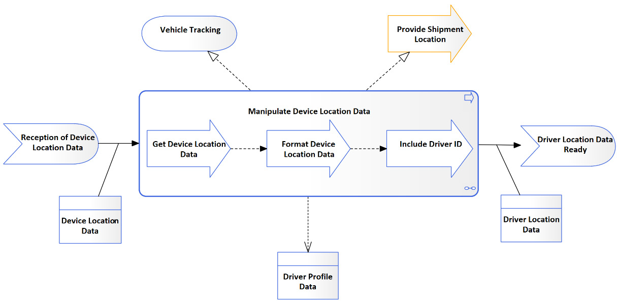
Figure 5.16 – The Manipulate Device Location Data application process diagram
As you can see, this diagram tells us what the process is, how it works, and what it needs to work. It tells us that it gets triggered by the reception of device location data, a sequence of child application processes performs a set of activities on the data to convert it into business meaningful data, and then an application event is triggered to inform the event listener that the data is available for consumption. The Manipulate Device Location Data application process receives the raw device location data, accesses the driver profile data, and produces the driver location data. Finally, the diagram tells us that the application process realizes the Provide Shipment Location business processes and realizes the Vehicle Tracking application service.
Now, we need to make this diagram a child diagram of the Manipulate Device Location Data application process element. If you've forgotten how, here is a quick reminder:
- Right-click on the Manipulate Device Location Data application process element.
- Select New Child Diagram > Select Composite Diagram from the context menu.
- Select the diagram from the tree or search for it, and then click OK.
The repository users are now able to navigate to this context diagram from any other diagram that contains the Manipulate Device Location Data application process element.
Many people expect to see activities and decisions in a process model because this is how the Unified Modeling Language (UML) activity diagrams and Business Process Modeling Notation (BPMN) diagrams behave. ArchiMate® is an architecture language, and as such, it is not designed to replace UML or BPMN when it comes to modeling processes in detail. Most business and IT stakeholders are quite familiar with these standards, and ArchiMate® does not need to show complex flows with activities, decisions, forks, joins, and swim lanes. Most developers understand UML, and the application process context diagrams are not detailed enough to give developers everything they need to implement a solution.
When you need to model processes in detail, it's best to use the standard that can satisfy those requirements. However, you need to keep in mind that mixing multiple standards in the same repository should be handled with extra care, as some elements and relationships may get duplicated, and some relationships between elements from different standards might not be possible. For example, you cannot link ArchiMate® elements to UML elements, but you can link UML elements to ArchiMate® elements.
It is possible to stop enforcing the standard relationships rule by choosing Start > Desktop > Preferences > Preferences > Links and unchecking the Strict Connector Syntax option, as shown in the following figure:
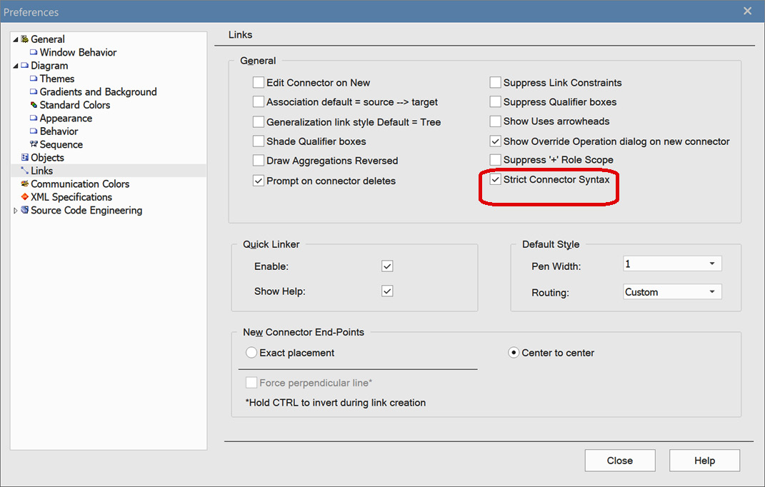
Figure 5.17 – The Sparx Preferences dialog
By disabling Strict Connector Syntax, Sparx will never enforce a syntax check on your connectors, which means that you can create any relationship between any two objects you choose, regardless of the standard. This way, you can create links between ArchiMate® and UML elements without any restriction. However, with flexibility comes more responsibility. Sparx will not be able to prevent you from creating incorrect relationships anymore if you disable this feature, so please be careful when you decide to opt for this. We do not advise you to do it unless you have a strong justification.
Since this book is about ArchiMate®, we will not go into more detail about creating UML diagrams. The main purpose of mentioning UML as an example is to let you know that your repository can consist of elements from multiple standards, even if this adds a level of complexity to managing and operating your repository. However, do not forget that enterprise architecture is about bridging gaps, not creating new ones. If stakeholders want processes to be modeled using UML, then let it be. It is easier for you to adapt than for the entire enterprise to adapt.
Another reason for mentioning UML is because we want to encourage developers and solution architects with no ArchiMate® experience to contribute to the repository with a standard that they feel comfortable with. UML is only one example, but there are dozens of modeling standards, and luckily, most of them are supported in Sparx. Adding a new standard to the repository must be approved by the enterprise architecture governing body to avoid ending up with a different standard for each person, which is far away from being a standard.
Important Note
Managing multiple standards in one repository can be hard, but managing multiple repositories in multiple modeling tools is much harder. You need to unify the architecture artifacts into a single repository as much as you can. Having diagrams following different standards in Visio, Lucid, and Visual Paradigm, for example, does not help toward this objective.
In the next section, we will introduce a new application behavioral element, which is the application function.
Introducing application functions
"An application function represents automated behavior that can be performed by an application component" (https://pubs.opengroup.org/architecture/archimate3-doc/chap09.html#_Toc10045397).
Application functions are application internal behavior elements, so they share a lot of characteristics with application processes and application interactions. However, application functions do not involve sequences, and they represent an abstracted ability that a component can perform.
Confusion between application functions and application processes is very common, and so is confusion between application functions and application services. We will help in identifying the differences between the three element types by highlighting the major differences. The easiest to identify are the processes because they involve a sequence, while functions and services are abstracted and do not involve a sequence. On the other hand, services are externally exposed while functions and processes are internal-facing. The following table can help you memorize the differences:

Table 5.1 – Differentiating between functions, services, and processes
You may think that application services are external-facing, but at the same time, they have a sequence of activities that enables them to provide or perform the service, which is not quite accurate. The sequence that shows how application services work is actually internal application processes realizing those services. Callers to a service do not know what the sequence is, so the sequence itself is not exposed to the enterprise.
Application components can perform many functions, but not all of them are necessarily exposed to the external enterprise. Let's clarify this with a simple example. We don't know how Microsoft Word works internally, so we as end users have no idea of what functions are performed by Word. We can only see and use what Word exposes externally to us, so we can only access its services. Mail merge is an example of an exposed service, but we cannot see or access the functions or the processes that are behind it. Application functions represent what the component architects and developers see, while application services represent what the component users and consumers see.
ArchiMate® provides two notations to model application functions, the rectangular and the borderless notations, as shown in the following diagram:
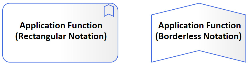
Figure 5.18 – Application Function notations
Application functions, processes, and services can have the same names, but that shouldn't confuse you either because it is all about the context. Printing, for example, is a function when we talk about an application's ability to print. Printing is considered a process when we start modeling how printing actually works, by defining the sequence of activities and the flow of data to be printed. Printing will be considered a service too if it is available for users to use. They all have the same name, but they are three different elements for three different purposes.
The following diagram shows the relationships between the three elements:

Figure 5.19 – Application functions, services, and processes
Note how an application function can be composed of application functions and aggregated of application processes. Application processes can also be composed of application functions and aggregated of application processes. This interchanged nested relationship can go to any desired level of depth until an atomic level of detail is reached, where elements cannot be broken down further. The following is an example of what the Tracking App application functions catalog can look like:
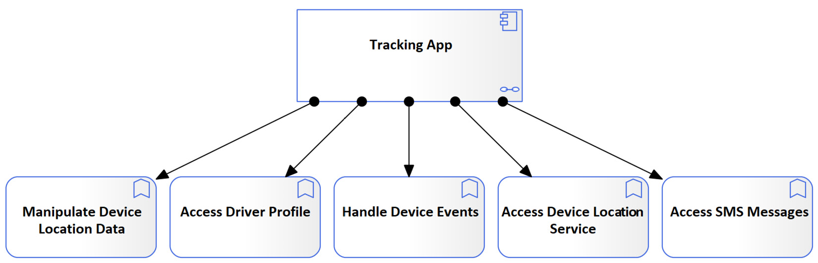
Figure 5.20 – The Tracking App application functions catalog
The focused metamodel for the application function is identical to the one for the application process, so we will not repeat it and leave it for you as an exercise. Just use Figure 5.15 as a base metamodel and replace the application process element with the application function element.
Next, we will look at another application internal behavior element, which is the application interaction.
Introducing application interactions
"An application interaction represents a unit of collective application behavior performed by (a collaboration of) two or more application components" (https://pubs.opengroup.org/architecture/archimate3-doc/chap09.html#_Toc10045398).
Application interactions are application internal behavior elements, so they share a lot of characteristics with application processes and application functions. The only difference is that application interactions describe the behavior of a collaboration of components, while application processes and application functions describe the behavior of a single application component.
ArchiMate® provides two notations for modeling application interactions, the rectangular and the borderless, as you can see in the following diagram:

Figure 5.21 – Application Interaction notations
The focused metamodel of the application interactions should be identical to the one for application processes, so please refer to Figure 5.15 and replace the focus element with the application interaction element.
Application interactions are not as commonly used as the other application internal behavior elements, so we will not spend too much time on them, and you can always refer to the ArchiMate® online documentation if you need to know more.
Next, we will talk about application events.
Introducing application events
"An application event represents an application state change" (https://pubs.opengroup.org/architecture/archimate3-doc/chap09.html#_Toc10045400).
A state change can occur due to internal or external factors such as a click on a command button by a user, reception of data from another application, completion of an application process, reaching a specific number of records, and reaching a predefined point of time. Event-driven programming is a very common way of building applications that react to events.
ArchiMate® provides two notations for modeling application events, the rectangular and the borderless, as shown in the following diagram:

Figure 5.22 – Application Event notations
Application events trigger the other application behavior elements, such as application processes, application functions, application services, and application interactions. Application events can also be triggered by those same elements. This means that an application event can trigger an application process to perform something specific, and when the process finishes, it can trigger another event, which in turn can trigger a second process, and so on. Figure 5.16 shows how one event triggers the Manipulate Device Location Data application process and shows that a second event is triggered upon process completion.
Application events realize business events and are realized by technology events. Business events such as Truck Moved are like application events but have pure business meaning. An application event such as Reception of Device Location Data can realize the Truck Moved business event. Additionally, the Reception of Device Location Data application event can be realized by the Phone GPS Location Changed technology event, as shown in the following figure:
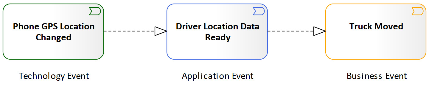
Figure 5.23 – Events realization at different layers
To build a reference that we can use in the future for modeling application events, we need to define a focused metamodel for it. At this point, we will assume that you have built some confidence in reading and understanding ArchiMate®'s metamodels and how to build a focused metamodel diagram in Sparx using your understanding. Therefore, we will not list the instructions for doing so and will provide the focused metamodel in the following diagram:

Figure 5.24 – The Application Event-focused metamodel
With this, we have reached the end of the second section of this chapter, which provided multiple examples for describing the behavior aspect of an application. In the next section, we will learn different ways of describing the structure of an application.
Describing application structure
The application structure describes the parts of the application that will be built. This includes the components and subcomponents, the interfaces, and the collaborations. They are the tangible parts of the application that can be deployed, copied, moved, deleted, or accessed. In this section, we will see how you can describe different parts of the application structure using different element types and relationships.
We will start this section by revisiting the application component, introducing the application interfaces, and then we will explore the application collaborations and how they can be helpful elements when modeling large applications.
Revisiting the application component
The Tracking App application component was introduced in Chapter 3, Kick-Starting Your Enterprise Architecture Repository, and the focused metamodel was introduced in Chapter 4, Maintaining Quality and Consistency in the Repository. So, we will not repeat what has been mentioned in the previous chapters, but we will introduce additional models that can be developed to give additional information about an application from different points of view.
It is important to bear in mind that as an enterprise architect, you do not usually enforce design decisions on the solution unless there are strong requirements that justify such enforcement. Your designs must stay at conceptual and logical levels where they can tell what is needed but not how to build it. What we will be doing in this subsection is looking at artifacts in the repository from the perspective of a solution architect and translating the conceptual ideas into logical designs. Solution architects are usually the ones who convert conceptual designs into logical and physical designs, and they are usually the ones who decide which design pattern and technologies to use.
When we introduced application functions, we modeled the Tracking App application functions catalog in Figure 5.20, but we didn't specify how these functions will be built. One solution architect may decide to build all these functions in a single component, a second solution architect may decide to build each function in its own subcomponent, while a third one may decide to follow a different design pattern.
For the sake of the context of this book, we will only show how to model the mapping between application functions and application subcomponents, without going into the details of which design pattern best fits our case. The target model will look like the following:

Figure 5.25 – Application functions mapped to application subcomponents
This model tells that the five desired functionalities will be implemented in four application subcomponents. Each component indicates which function or functions it is assigned to or, in other words, implements. Each of these subcomponents can be detailed even further, and more drill-down models can be developed until the desired level of detail is reached.
If the solution architect decided to go with a full-fledged microservices architecture, they may decide to have a separate application subcomponent assigned to each application process, no matter how small the process is. This gives ultimate scalability, extendibility, and reusability but adds a cost of development and maintainability overhead.
Another architect may decide to have all these functions realized in one monolith component for easier development but at the price of scalability, extendibility, and reusability. Deciding which design pattern to choose is not within the scope of this book. We have shown you one example for creating this mapping, and you can apply it in the way that best fits your environment and business requirements.
In the next subsection, we will introduce a new structure element, which is the application interface.
Introducing application interfaces
The application interface "represents a point of access where application services are made available to a user, another application component, or a node" (https://pubs.opengroup.org/architecture/archimate3-doc/chap09.html#_Toc10045394).
Application components encapsulate their internal structure and behavior and hide them from the external enterprise. For other enterprise elements (such as users, other application components, and system hardware and software), to access the services that are provided by an application component, they need to access them through an application interface. Application interfaces provide predefined controlled agreements known as service contracts to provide the services. Enterprise elements need to adhere to service contracts, or they will not be served. Service contracts provide the data schema, which describes the structure and format of data going into and out of an application interface. If you have experience in SOA, you must be familiar with modeling application interfaces, so you can easily apply your skills here.
ArchiMate® 3.1 provides two notations to model application interfaces, as you can see in the following figure:
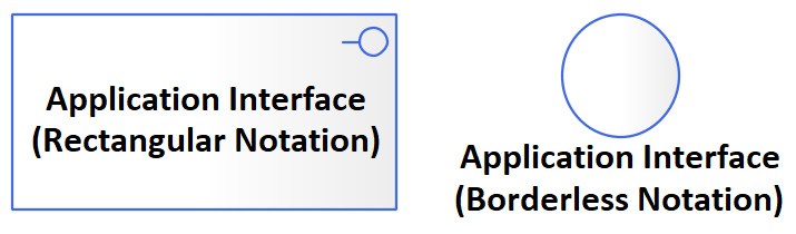
Figure 5.26 – ArchiMate® 3.1 Application Interface notations
As always, it is up to you to choose the notation that creates less confusion for you and, more importantly, your audience. Let's see how the application interface-focused metamodel looks before looking at some modeling examples.
Defining the application interface-focused metamodel
As we have done for other focused metamodels, we will use the ArchiMate® 3.1 specification to guide our focused metamodel development. We will translate our understanding and interpretation of the standard into an easy-to-understand reference that will help to maintain consistency within the enterprise architecture repository.
Since you already have confidence in reading the ArchiMate® metamodels and building focused metamodels in Sparx, we will skip the step-by-step instructions and introduce the focused metamodel directly. Your application interface-focused metamodel should look like the following:

Figure 5.27 – The Application Interface-focused metamodel
We hope that this focused metamodel will guide you in modeling more application interfaces in your work environment and empower your team with clearer and easier-to-follow references.
In the next subsection, we will look at the different types of application interfaces and ways of modeling them.
Modeling application interfaces
As we have mentioned in this section's introduction, application interfaces are the access point for accessing application services. Figure 5.7 has already covered this mapping by showing how the service will be accessible through six different application interfaces. What might be helpful to show now is how these interfaces will be structured within the Tracking App component.
Even though we will not enforce any design decisions, we know for sure that we will need at least two UIs – one for Android users and one for iOS users. We will most probably need one for web users, one for the command line, and one for API calls. However, application interfaces are not deployable objects. They cannot exist by themselves and can only be part of an application component. This means that to have an Android UI, you need to have an Android UI component that will be installed on the phone. That component will contain the Android UI and be responsible for sending and receiving data from and to the UI. The same logic applies to the iOS application interface.
The following model shows how Tracking App can be composed of multiple UI application components, and multiple application interfaces as well:

Figure 5.28 – The Tracking App application interfaces
You may agree or disagree on the design, but remember that we're just clarifying the idea of modeling application interfaces with examples. Another architect may decide to have the web UI, command-line UI, SOAP API, and REST API each in a separate application component, just like the Android UI component, which are valid to use. Using different design patterns and the advantages of one over another are covered in many other books on the market. From a modeling perspective, we hope that you've got the idea that you can apply the idea in any way that makes sense to you and is acceptable to your team.
If you want to detail how the command-line UI works, for example, you can model that in a separate child diagram, as follows:
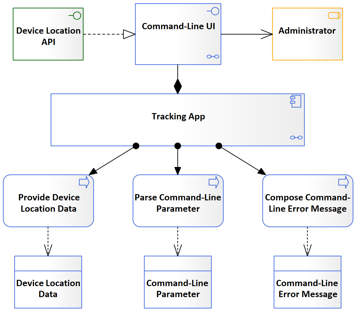
Figure 5.29 – The Command-Line UI application interface model
As we said earlier, you may agree or disagree with the design itself, but this is one possible way to model an application interface in ArchiMate®. Once you get the idea and understand the local issue that you need to resolve, the sky is your limit to model whatever makes sense in your work environment.
In the next section, we will introduce another application structural element, which is application collaboration.
Introducing application collaborations
"An application collaboration represents an aggregate of two or more application internal active structure elements that work together to perform collective application behavior" (https://pubs.opengroup.org/architecture/archimate3-doc/chap09.html#_Toc10045393).
Application collaborations, according to the definition, are structural elements that are aggregated of two or more structural elements. A very common example is Microsoft Office, which is an aggregation of Word, Excel, PowerPoint, Outlook, and other products. Each product is independent of the other, but combined, they are known as the Microsoft Office product. This is an example of weak collaboration where individual components still maintain their independence.
Some application collaborations can take stronger forms and are more than just a gathering of multiple components, and more like unification. When independent components are combined, they provide a new set of application behaviors that cannot be performed by any one of them separately. Additionally, in some cases of strong application collaborations, access to the individual components will no longer be allowed through their own interfaces but through new ones that belong to the collaboration element. It all depends on how strong or weak you or the solution architect want this collaboration to be.
ArchiMate® 3.1 provides two notations to model application collaboration elements, the rectangular and the borderless, as with most of the ArchiMate® elements:

Figure 5.30 – Application Collaboration notations
The Application Collaboration element has the same relationships that the application component has, so they both share the same metamodel. Refer to Figure 4.9 in Chapter 4, Maintaining Quality and Consistency in the Repository, to see the possible elements that can relate to an application collaboration and the relationships that can occur between them.
Figure 5.31 is an example of an application collaboration. It shows a conceptual design of the e-commerce platform that ABC Trading is targeting to build, which aggregates multiple application components and provides multiple application interfaces. It also shows that the platform will do the following:
- Be served by cloud computing services
- Be served by the single sign-on service
- Provide an e-trading service
- Provide users with the ability to manage a unified user profile for all these different components
One thing to keep in mind about application collaborations is that they can assign their internal application behavior to application interaction elements in addition to application processes and application functions, as shown here:

Figure 5.31 – An AECP application collaboration model
That was an example to simplify the idea of modeling application collaborations, and we're quite sure that you will be able to project this example onto real work examples to provide your stakeholders with models describing their visionary solutions. That's what enterprise architects do – help stakeholders have better views from different perspectives to enable them to make better decisions.
In the next section, we will see how to model data in the enterprise without stepping on the toes of database administrators.
Introducing data objects
"A data object represents data structured for automated processing" (https://pubs.opengroup.org/architecture/archimate3-doc/chap09.html#_Toc10045404).
Applications are built to automate the process of manipulating data in one way or another, whether it is financial data, human resources data, inventory data, video clips, soundtracks, virtual reality images, games, and so on. The list is long.
Data, by itself, is of little use if it is not opened and processed with the right application component. A .jpg file, for example, does not have any value for you if you don't have a JPG viewer installed. A database record has no value to you if it is not displayed on the screen, processed, reported in a report, printed on paper, or sent to another application component. Therefore, ArchiMate® 3.1 considers data objects as passive elements because they must be manipulated or accessed by another element.
Unlike most elements in the ArchiMate® 3.1 specification, there is a single notation for modeling data objects, as shown in the following figure:
Figure 5.32 – ArchiMate® 3.1 Data Object notation
Data objects must not be confused with databases. Databases are one type of storage for data objects. Data objects can exist in flat files, spreadsheets, relational tables, documents, and many other forms. The driver profile in our Tracking App, for example, is a data object, regardless of where it is stored and in what format. Whenever we describe the actual locations where the driver profile data is stored or how it is physically persisted, then we're more likely describing the technology object that realizes this data object.
Let's talk more about data at the different layers of the enterprise and how to differentiate between them.
Differentiating data at the different architecture layers
At the technology layer, we can model how data is stored in the form of technology objects and technology artifacts. You can think of technology objects as data at rest, while data objects represent data in motion or transit. A high-level technology object model can show the storage of the Driver Profile as a Profiles Data store.
Data stores do not tell us whether we are storing data in a relational database, a .json file, or a flat text file. All of these are considered technology artifacts realizing data objects from the application layer. When you need to provide a deeper view of this data store, such as the database tables that form it, then you are moving away from being abstract to being more specific, which is another view for another stakeholder.
A database table is yet another technology object at a lower level of detail. A third level of detail can describe the data schema for a specific .json file with all the required tags and headers to physically represent the file. At this level of detail, ArchiMate® provides another element, the technology artifact, which is a specialized element of technology objects. We will look at technology objects and technology artifacts in more detail in Chapter 6, Modeling in the Technology Layer.
Data objects at the application layer represent data instances in memory. Data objects show the movement of data between components. As you can see in Figure 3.16 of Chapter 3, Kick-Starting Your Enterprise Architecture Repository, and Figure 5.12, we have indicated the data objects that were passed in or out of different types of elements. Data objects realize business objects.
Modeling data at the business layer does not show any physical or implementation detail. The business might treat all employee profiles the same way, and it does not matter to the business whether these profiles are in a computer system or a paper folder. All that matters to the business is that there is a data structure that holds employees' profiles, including drivers' profiles. Business objects are realized by data objects when they are implemented within an application. We will talk in more detail about business objects in Chapter 8, Business Architecture Models.
Next, we will look at our final reference-focused metamodel in the application layer. More elements will be introduced in later chapters, and more focused metamodels will be built.
Defining the data object-focused metamodel
If you have read the ArchiMate® specification properly and modeled it in Sparx the way that we have guided you, your Data Object-focused metamodel should look like the following:

Figure 5.33 – The Data Object-focused metamodel
Let's look at a data object model to see how data objects can be modeled.
Modeling data objects
There is no specified size for how big or small a data object can be. It can be as small as a single attribute that you pass from one application process to another. It can also be as big as a dataset that composes many objects into one big object.
The Driver Profile data object, for example, can consist of many smaller data objects, such as user accounts, driver demographics, addresses, and contact numbers. Each of them can be decomposed further into smaller data objects, and they can also be aggregated with other data objects to form new data objects:

Figure 5.34 – The Driver Profile data object decomposition
In some cases, you may find a need to pass the entire driver profile between components, while in some other cases, you may only need to pass an address. The question that will come to the architect's mind is, shall I define the attributes of the data objects?
The answer is, it depends on your target audience, but in most cases, you do not have to define the attributes unless you are passing attributes individually between components and want your model to clearly depict this data exchange. If you are defining the attributes, remember that you need to coordinate with the data architect to ensure that you are not forcing any design decision on them.
There are many ways to model data objects, but to create consistent models that adhere to standards, you will need a metamodel. Let's recap what we have learned in this chapter.
Summary
In this chapter, we've covered some of the most fundamental aspects of enterprise architecture modeling. We've looked at the differences between behavioral and structural models and the elements that make them up. We've also looked at some common diagram types, such as the context diagram and the catalog. We've learned more about how to manipulate our models in Sparx and how to connect them to each other to provide an easy navigation experience for readers.
You will see that many of these aspects will be reinforced in subsequent chapters as we cover aspects of the technology and business layers of ArchiMate®. This is because many of the element types across these layers share a common function but with a differing scope. There are services, functions, processes, events, components, and interfaces in the business, application, and technology layers. If you understand the thin lines that differentiate each element in each layer, you've mastered ArchiMate® and enterprise architecture, literally!
We will continue to use the focused metamodel in introducing new elements; however, we are guessing that you've had enough practice creating your own focused metamodels and that we don't need to show you how to do that anymore. We'll just introduce the models. We will also continue to salt each chapter with tidbits of advice from our decades of experience. Feel free to take that advice with a grain of salt. This practice we call architecture is always changing. You need to change with it.
In the next chapter, we will cover the technology layer of the enterprise.