
Chapter 6: Modeling in the Technology Layer
One of the difficult tasks enterprise architects must tackle is describing technology environments at the correct level of abstraction. If the model is too detailed, as architects, we are seen as too prescriptive. If it's not detailed enough, we are being vague. Either of these conditions tends to lead to the ivory tower syndrome as we are seen as being too far from reality. Selecting the perfect level of granularity can sometimes seem like an art.
The creators of the ArchiMate® language recognized this fact and took it into consideration when designing the language. Each layer's elements are based on a small, core set of elements that have similar attributes across layers (see Figure 6.13 further on in this chapter). As you read through this chapter, you should see these similarities begin to appear. You should also begin to get a sense of the level of granularity necessary for architecture descriptions and how to create them without duplicating information.
In this chapter, we cover elements and relationships of the Technology Layer of the ArchiMate® 3.1 standard. This includes a new sub-layer of the Technology Layer called the Physical Layer for modeling physical environments. The following sections are included in this chapter:
- Modeling technology environments
- Modeling physical environments
- Modeling networks
As always, we include examples and tips for using Sparx along the way.
Technical requirements
This chapter does not require any additional technical requirements other than having Sparx Systems Enterprise Architect (EA). If you do not have a licensed copy, you can download a fully functional 30-days trial version from the Sparx Systems website (https://sparxsystems.com/products/ea/trial/request.html).
We will continue adding the content of this chapter in the same EA repository that we built in Chapter 3, Kick-Starting Your Enterprise Architecture Repository, and Chapter 4, Maintaining Quality and Consistency in the Repository. If you have not read these two chapters, we strongly advise you to read them first then come back to read this chapter. If you want, you can download the repository file of this chapter from GitHub at https://github.com/PacktPublishing/Practical-Model-Driven-Enterprise-Architecture/blob/main/Chapter06/EA%20Repository.eapx instead of starting from scratch. Some of the steps in this chapter depend on elements that have been already created in the repository, so it is better not to start this chapter with an empty repository.
We will use the following ArchiMate® 3.1 specification chapters to guide our development:
- Chapter 5, Relationships (https://pubs.opengroup.org/architecture/archimate3-doc/chap05.html#_Toc10045310)
- Chapter 10, Technology Layer (https://pubs.opengroup.org/architecture/archimate3-doc/chap10.html#_Toc10045407)
- Chapter 11, Physical Elements (https://pubs.opengroup.org/architecture/archimate3-doc/chap11.html#_Toc10045429)
- Chapter 12, Relationships Between Core Layers (https://pubs.opengroup.org/architecture/archimate3-doc/chap12.html#_Toc10045440)
Modeling technology environments
In this section, we will cover the core elements of the Technology Layer of ArchiMate® 3.1. The elements discussed in this section are identified in the following diagram:
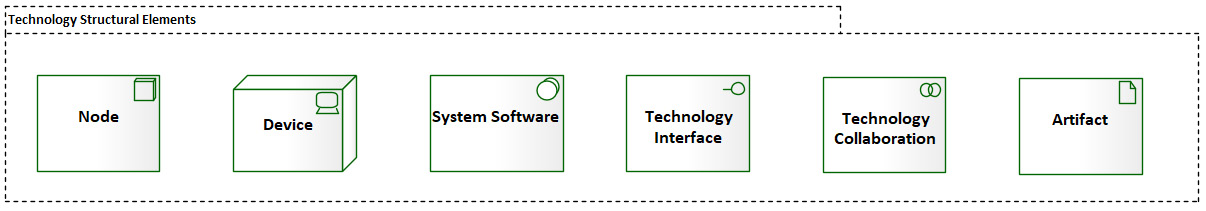
Figure 6.1 – Technology structural elements
At the core of the Technology Layer of ArchiMate® are two new elements: the Device and System Software elements. These two elements are both technology internal active structure elements and they both inherit from the same parent element, the technology node. As per the ArchiMate® 3.1 specification, a technology node—or node, in short—"represents a computational or physical resource that hosts, manipulates, or interacts with other computational or physical resources" (https://pubs.opengroup.org/architecture/archimate3-doc/chap10.html#_Toc10045410).
In simpler words, a node is any hardware or software that is used to store, process, monitor, manage, streamline, and communicate with other hardware or software. If your background is in networking, you may be wondering about network nodes. ArchiMate® makes no graphical distinction between network nodes and other types of nodes. For this reason, we usually refine the node type by giving it an appropriate name. For example, a network node may actually contain the word network in the element name.
As with most enterprise elements, ArchiMate® provides two notations for modeling nodes—rectangular notation and borderless notation, as you can see in the following screenshot:
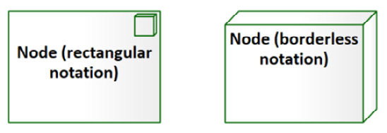
Figure 6.2 – ArchiMate® 3.1 node notations
Since the device and the system software elements are a specialization of the node element, they have the same relationships as the node. This means that all the relationships that you can see in the technology node-focused metamodel (see Figure 6.12) are applicable for the device and system software. There are cases where you need to be more precise about what a specific node is, and this is where you need to use either a device or system software. Let's take a look at some examples of modeling with node elements.
Examples of technology models
We need to model some of the technology components involved in serving web requests at ABC Trading. For this, we will build up a diagram incrementally as we go. This approach lets us demonstrate a feature of Sparx, the diagram layering feature. We'll explain that later. First, let's look at the diagram here:
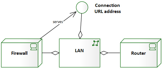
Figure 6.3 – Layer 1 network technologies
We've not covered these element types in detail yet, but we will. The device element will be covered in the Using the device element subsection. The network element is presented in the Modeling networks section of this chapter. For now, let's walk through the first iteration of this diagram. We see that the following applies:
- We have a Local Area Network (LAN).
- We use the aggregation relationship to show that the LAN is made up of a firewall and a router.
- We interface with the LAN through a connection Uniform Resource Locator (URL) address.
- The firewall serves to protect the interface. We go into a little more detail on this in Chapter 7, Enterprise-Level Technology Architecture Models.
While that's not much information, we will build upon it. The next layer shows some of the devices that connect to the LAN, as illustrated in the following diagram:

Figure 6.4 – Layer 2 connected server groups
In this layer, we have added server group elements. We've used the collaboration element type to represent a server group. In this case, we have a collaboration of servers that serve web pages. We see that there are two server groups connected to the LAN. Unlike the firewall and router, the server groups do not make up the LAN—they connect to it. We show a connection using a simple association link. The next layer expands on the server groups, as illustrated in the following diagram:

Figure 6.5 – Layer 3 servers
In this layer, we see that Server Group 1 is made up of three servers, and Server Group 2 has two servers. The next layer shows that all these servers serve the same set of web pages, as illustrated in the following diagram:
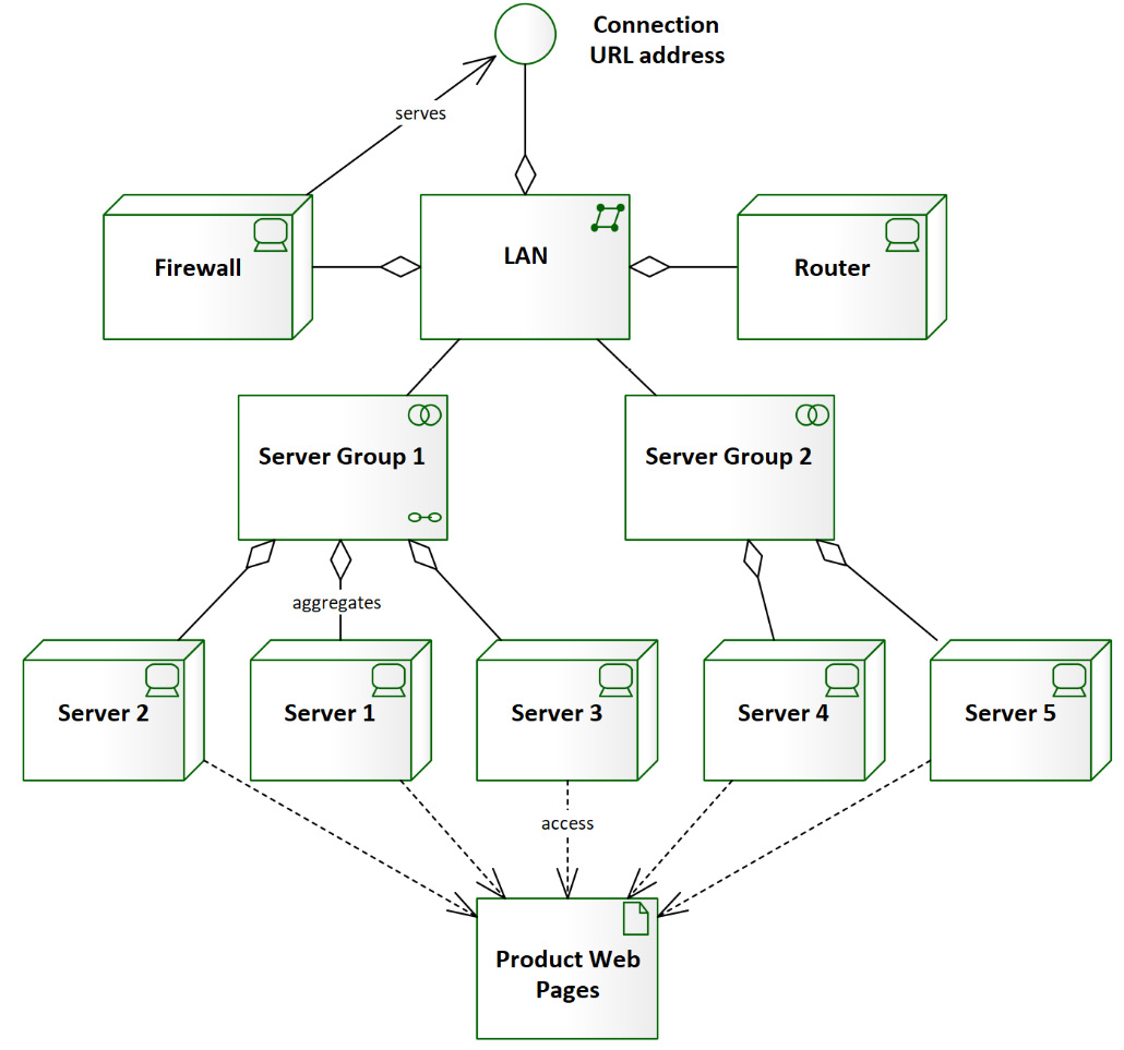
Figure 6.6 – Layer 4 web pages
There are two problems with Layer 4 in the diagram. As we know, servers don't serve web pages directly. We're missing some intermediate technologies.
The other problem is that this diagram is already becoming a bit too cluttered. We need to pare it down so that the reader can focus on what we are conveying. We've all seen the huge Entity-Relationship Diagrams (ERDs) with 50 or more elements and endless connectors running all over the place. They often are hung on the wall like a trophy as if to say: Look what I have conquered! While they may look impressive or intimidating, they are usually very ineffective. The information may be useful, but the diagrams are useless—they are too difficult to read. We also need to consider our audience. How much of what is presented in Figure 6.6 is valuable to them? They probably don't need to know about the individual servers involved in the solution.
So, how do we add the missing technologies without overloading our diagram or our audience? The answer is to create another diagram. Simply select an area of the diagram that needs more detail and make it the focus of the next diagram. In the following diagram, we have expanded the information on the Server Group 1 collaboration element:

Figure 6.7 – Server group 1 detail
When creating diagrams that are dependent on each other such as we have just done, we relate the diagrams by including a common element. In our case, the element that links our two diagrams is the server group 1 element. All of the rest of the elements should be unique to each diagram. If you look back at Figure 6.5, Figure 6.6, and Figure 6.7, you'll notice that we have included server elements in all of them. We need to remove the servers from Figure 6.6. You might think: Why bother? But should we ever need to change the servers that comprise server group 1, we would prefer to minimize the number of diagrams we need to modify. The following diagram shows the new parent technology stack:

Figure 6.8 – Final web-servicing model
Additionally, we added Figure 6.7 as a child diagram to the server group 1 element in Figure 6.8. This is indicated by the chain-link icon in the lower-right corner of the element. Now, we can easily navigate between the two diagrams. We have reduced clutter on each diagram, but we have also provided two layers of granularity for our audience. You can now choose the level of detail provided to your audience without duplicating information. Next, we will cover the diagram-layering feature of Sparx that we used to build and display this structure diagram.
Diagram filters and layers
Adding filters or layers to a diagram in Sparx is a very convenient way to show diagram features and elements incrementally. The Filters option allows us to hide or mask elements based on attributes such as stereotype, version, status, and date. Filters are diagram-independent—they can be applied to any diagram. The Layers option performs a similar function based on the diagram elements you select. For that reason, layers are specific to a diagram. To access this feature, go to Layout > Tools > Filters & Layers. The following window appears:

Figure 6.9 – Filters & Layers window
As with other windows in Sparx, you can choose to dock this window on the Sparx User Interface (UI). The first two buttons on the Layers ribbon allow you to add or remove a layer from a diagram. The next two buttons let you add or remove selected elements from a selected layer. Finally, checking or unchecking the checkbox beside Layer displays or hides elements of a layer from a diagram. Just as with any other feature, it's best to experiment with this one to fully understand how it works.
If you'd like to play around with this example diagram, you can find it in this chapter's GitHub repository at https://github.com/PacktPublishing/Practical-Model-Driven-Enterprise-Architecture/blob/main/Chapter06/EA%20Repository.eapx. Once you're in the Sparx repository, the diagram can be found in the following location:

Figure 6.10 – Example diagram location
Now, let's look at another way to model system structure—the technology stack.
Technology stacks
One specific technique for modeling system structure is a technology stack diagram. To our knowledge, there is no standard for this technique; it's more of a common practice. The idea is to represent technology dependencies by placing dependent technologies on top of the technology on which it is dependent. In this sense, we literally stack the technologies. Have a look at the following example depiction of a Linux-Apache-MySQL-PHP: Hypertext Preprocessor (PHP) (LAMP) technology stack:

Figure 6.11 – LAMP technology stack
LAMP represents one somewhat common combination of technologies used for web development. There are many others, of course.
In this diagram, each system software element is dependent on the one below it. Dependencies flow down, never up. So, in this example, PHP is dependent on all of the other technologies. As you can see, there are no visible links in this diagram. They are all implied. This renders such diagrams of somewhat limited use. There is no information conveyed by technology stack diagrams that cannot be conveyed in other standard structure diagrams. We include it here because if you've never heard of it before, you will likely hear of it in the future.
Interpreting the standard
To build a node-focused metamodel, we will need to interpret the standard into a list of statements describing elements and relations; then, we will translate these statements into a diagram. We have done similar steps for many elements in previous chapters, so if you have not read Chapter 4, Maintaining Quality and Consistency in the Repository, we highly recommend that you do because it contains step-by-step instructions for performing many of the actions in this chapter and most of the remaining chapters.
A node is a technology element, so we will use the following chapters from the ArchiMate® 3.1 specification as references:
- Chapter 5, Relationships (https://pubs.opengroup.org/architecture/archimate3-doc/chap05.html#_Toc10045310)
- Chapter 10, Technology Layer (https://pubs.opengroup.org/architecture/archimate3-doc/chap10.html#_Toc10045407)
- Chapter 12, Relationships Between Core Layers (https://pubs.opengroup.org/architecture/archimate3-doc/chap12.html#_Toc10045440)
We have all the information that we need to build a focused metamodel, so we will put all the aforementioned points in a diagram in Sparx, as you will see in the next subsection.
Using the node element
Since you have more confidence and experience in Sparx by now, we will assume that you know where to find all these elements, how to change toolboxes, how to place elements, how to create proper relationships, and how to style your elements and organize your diagram. Whenever you're in doubt, refer to Chapter 4, Maintaining Quality and Consistency in the Repository. The node-focused metamodel should look like this:

Figure 6.12 – Technology node-focused metamodel
This diagram references the core elements of the Technology Layer. We will add some more elements and relationships in the Modeling physical environments section later in this chapter.
After reading the previous chapter, you may have detected a pattern forming among the layers of ArchiMate®. You are not mistaken. It is no accident that the elements in each layer have complementary elements in the other layers. These complementary elements have similar characteristics within the scope of their layer. For example, the business actor element performs a similar function in the Business Layer, as does the component element in the Application Layer and as the node element in the Technology Layer. The following diagram shows the alignment of most of the core elements in ArchiMate® 3.1:

Figure 6.13 – Element alignment among layers
Now that we've covered nodes, we take a deeper look at some of the specific structural elements in the Technology Layer. In this section, we will present focused metamodels for the following structural elements:
- Device
- System software
- Technology interface
- Technology collaboration
Network and path element types are covered in the Modeling networks section later in this chapter. Technology behavioral elements are covered in Chapter 7, Enterprise-Level Technology Architecture Models. Let's get started.
Using the device element
According to ArchiMate®, "A device represents a physical IT resource upon which system software and artifacts may be stored or deployed for execution." (https://pubs.opengroup.org/architecture/archimate3-doc/chap10.html#_Toc10045411)
The device element icon looks like a terminal or desktop computer, as illustrated in the following diagram:
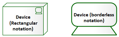
Figure 6.14 – Device icon
The device element is a specialization of the node element. It represents a physical device or piece of equipment. Examples of devices include:
- Servers
- Monitors
- Routers
- Cell phones
- Tablet computers
- Mainframe computers
Any physical Information Technology (IT)-related thing that may serve the Application Layer or other elements in the Technology Layer can be a device. In the following diagram, we show that a Desktop PC is an aggregation of a CPU, Keyboard, Monitor, Mouse, and Cables:

Figure 6.15 – Device example
Because a device is a type of node element, its relationships look similar to those of a node, as illustrated in the following diagram:

Figure 6.16 – Device-focused metamodel
Devices can be made up of other devices. Devices may be assigned to system software, technology functions, processes, interactions, or events. Devices may collaborate with other devices to provide functionality.
Where a device exists, there is often system software to manipulate that device. Let's look at the system software element next.
Using the system software element
According to ArchiMate®, "System software represents software that provides or contributes to an environment for storing, executing, and using software or data deployed within it." (https://pubs.opengroup.org/architecture/archimate3-doc/chap10.html#_Toc10045412)
The system software icon is a box with a disk in the upper-right corner, as shown in the following diagram:
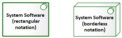
Figure 6.17 – System software icon
The system software element is a specialization of the node element. It represents software used to support the function of a device or other Technology Layer elements. Examples of system software include the following:
- Operating systems
- Application servers, web servers, and transaction monitors
- Relational Database Management Systems (RDBMSs)
- Backup and restore software
- Network firewall, routing, and monitoring software
- Report formatting systems
- Editors and word processors
- Security management software
- Device controller software
- Code compilers and interpreters
System software contains no business-specific logic. Once the software is applied to a business domain such as finance or inventory, it becomes an application. Application software can use system software to accomplish its business goal, but the system software knows nothing about that goal. The best example of this is when application software runs on an operating system. In such a case, the operating system has no application-specific knowledge. It simply acts at the behest of the application to open files, allocate memory, and other such technical tasks.
The following diagram expands on the example presented previously to include system software such as operating systems:
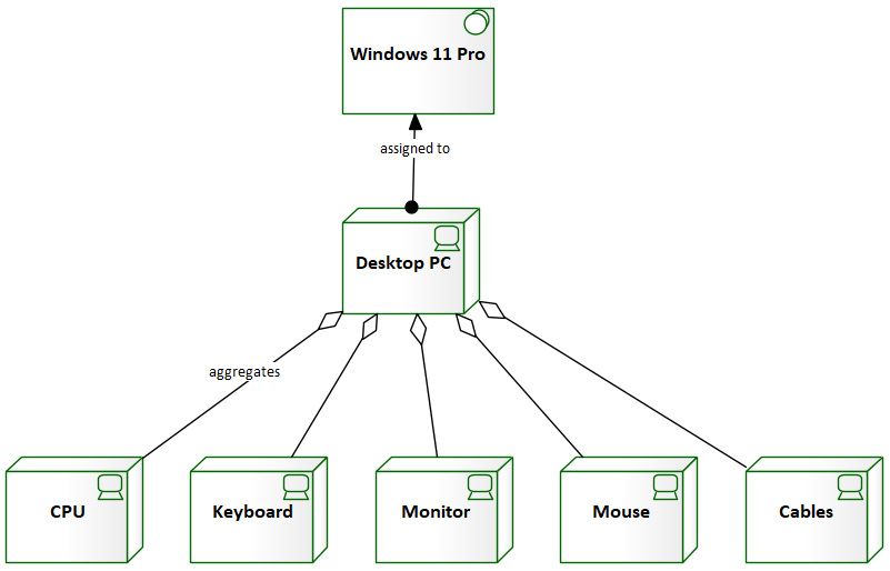
Figure 6.18 – A device assigned to system software
In this example, we see that a Desktop PC device is assigned to the Windows 11 Pro system software. In the next example, we see that system software may serve other system software:

Figure 6.19 – System software served by the operating system
As with the device element, because the system software element is a type of node element, its relationships look similar to those of a node, as shown next:
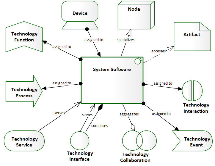
Figure 6.20 – System software-focused metamodel
Applications interact with system software through well-known technology interfaces. That's our next topic.
Using the technology interface element
The technology interface performs a similar function to the application interface, only in the Technology Layer. According to ArchiMate®, "A technology interface specifies how the technology services of a node can be accessed by other nodes. A technology interface exposes a technology service to the environment." (https://pubs.opengroup.org/architecture/archimate3-doc/chap10.html#_Toc10045414)
The technology interface element icon shown next is a simple circle. Sometimes, when a connector is applied to it, it's referred to as a lollipop:
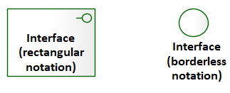
Figure 6.21 – Technology interface icon
The technology interface represents functionality exposed to its environment. Technology interfaces come in different forms. Some examples of technology interface types include the following:
- UIs
- Application Programming Interfaces (APIs)
- Communication interfaces (signals, sockets, web)
- File-based interfaces
The technology interface element can represent different levels of granularity or abstraction from generalized groups of interfaces such as the prior examples or to specific actions such as the following:
- Opening a file
- Creating a table
- Opening a socket
- Receiving a message
One example of system software that supports a rich set of interfaces is the Linux operating system. The following diagram depicts a few of those interfaces:
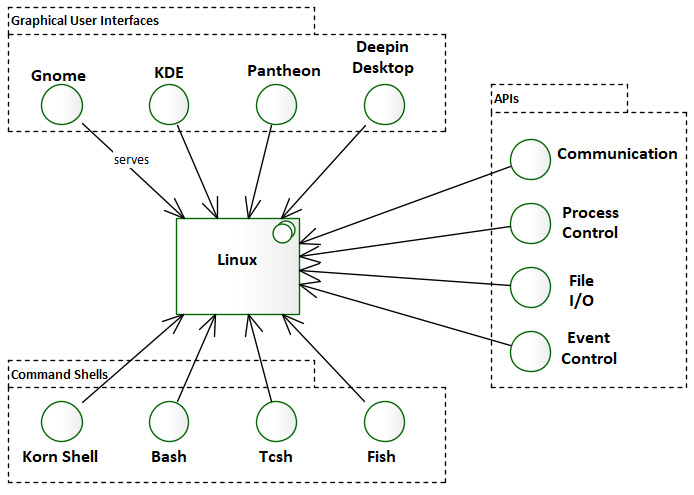
Figure 6.22 – Some interfaces on the Linux operating system
As you can see, Linux users can choose one of several Graphical User Interfaces (GUIs) or command shells to interact with the operating system. Linux also supports a rich set of APIs.
The most common relationships of the technology interface element are represented in the following focused metamodel:
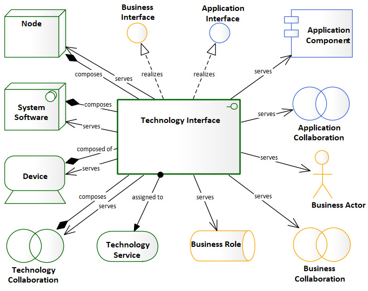
Figure 6.23 – Technology interface-focused metamodel
While an interface is generally exposed by a node, the functionality exposed by that interface may be the work of two or more nodes. Such functionality is a technology collaboration. We will look at the technology collaboration element next.
Using the technology collaboration element
According to the ArchiMate® standard, "A technology collaboration represents an aggregate of two or more technology internal active structure elements that work together to perform collective technology behavior." (https://pubs.opengroup.org/architecture/archimate3-doc/chap10.html#_Toc10045413)
Just as with an application collaboration, the icon representing a technology collaboration appears as two intersecting circles, as shown here:

Figure 6.24 – Technology collaboration icon
In Figure 6.5, Figure 6.6, Figure 6.7, Figure 6.8, and Figure 6.9, we used a technology collaboration to represent a cluster of servers called server group 1 and server group 2. The servers in each cluster collaborated to deliver web pages. Technology collaboration elements are generally paired with technology interaction behavioral elements to describe the role of each element in delivering the functionality. Our example didn't need a technology interaction element because each server's role is identical to the next, and serving web pages follows a well-known interaction pattern. Besides, our focus in this chapter is on structural elements. We'll be reviewing behavioral elements in the next chapter.
The following diagram shows the relationships of the technology collaboration element:

Figure 6.25 – Technology collaboration-focused metamodel
In the previous chapter, we learned about the application data object. The physical form of data in the Technology Layer is an artifact. We discuss that element next.
Using the technology artifact element
In ArchiMate®, an artifact is to the Technology Layer what a data object is to the Application Layer and what a business object is to the Business Layer. That is to say that an artifact represents data but in physical form. Unlike the Technology Layer elements discussed so far, an artifact is a specialization of a technology object (https://pubs.opengroup.org/architecture/archimate3-doc/chap10.html#_Toc10045426).
The technology artifact element resembles a box with an icon in the corner that resembles a piece of paper with one corner folded over, as shown here:
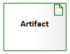
Figure 6.26 – The technology artifact
Examples of technology artifacts include the following:
- Physical data files
- Deployable objects such as .jar files and .war files
- Database tables
- Source files, executable files, and scripts
- Configuration files
The name of the artifact element should reflect the name of the physical file. Let's take a look at this element's focused metamodel in the following diagram:
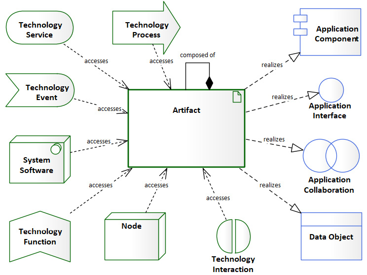
Figure 6.27 – Artifact-focused metamodel
As mentioned earlier, there are other structural elements in the Technology Layer, but we will look at those in the Modeling networks section later in this chapter. In the next section, we will look at modeling physical environments.
Modeling physical environments
Now that we understand the core Technology Layer elements in ArchiMate®, we need to establish a bit of context with respect to ABC Trading. Establishing context around a particular business domain can mean different things to different people. For me, once I have learned what a company does, I like to know where they do it, and with which resources.
In this section, we will use the elements and relationships of the physical sub-layer of the Technology Layer. The physical layer subset is relatively new to ArchiMate®. It was introduced in version 3.1. We will first look at the specific elements and relationships that make up the physical layer, then we will look at some examples of how those elements can be applied to ABC Trading.
The element types covered in this section are shown in the following diagram:
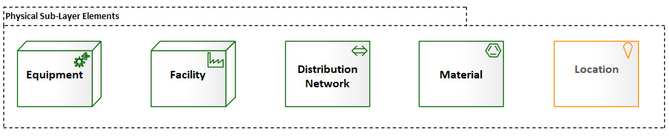
Figure 6.28 – Physical elements covered in this section
Let's have a look at each of these physical elements in the following subsections.
Understanding the equipment element
The equipment element serves as the core element of the physical layer (https://pubs.opengroup.org/architecture/archimate3-doc/chap11.html#_Toc10045432).
The equipment element is a specialization of the node element. It represents machines, tools, or other such physical mechanisms used by the organization. Equipment can comprise other equipment elements. The equipment icon resembles a set of meshed gears, as shown here:

Figure 6.29 – Equipment icon
The following equipment-focused metamodel diagram shows some of the possible relationships of the equipment element:

Figure 6.30 – Equipment-focused metamodel
Let's now turn to another structural element—the facility element.
Understanding the facility element
The facility element is a specialization of the node element and can be used to represent any physical structure or environment that plays an important role in the organization (https://pubs.opengroup.org/architecture/archimate3-doc/chap11.html#_Toc10045433).
The icon for the facility element resembles a factory, as seen here:

Figure 6.31 – Facility icon
The following facility-focused metamodel diagram depicts the relationships of the facility element:
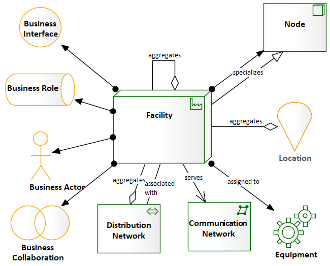
Figure 6.32 – Facility-focused metamodel
The next element in the physical layer is the distribution network element.
Understanding the distribution network element
The distribution network element is an object element. It represents a means of transporting physical things such as material, energy, and much more (https://pubs.opengroup.org/architecture/archimate3-doc/chap11.html#_Toc10045434).
The distribution network icon appears as a double-ended arrow, as depicted in the following diagram:

Figure 6.33 – Distribution network
The distribution network element can have the following relationships:
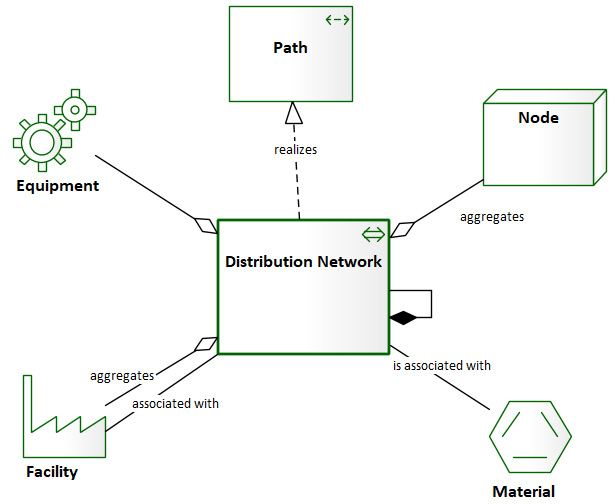
Figure 6.34 – Distribution network-focused metamodel
The next element we look at is the material element.
Understanding the material element
The material element is a passive structure element that is used to represent raw material, physical products, or energy (https://pubs.opengroup.org/architecture/archimate3-doc/chap11.html#_Toc10045437).
We use the material element to represent the products we distribute. The material icon is a hexagon, as shown here:
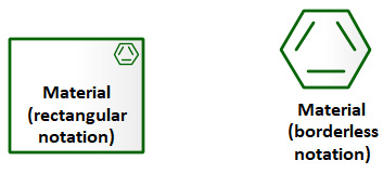
Figure 6.35 – Material icon
The material element-focused metamodel is depicted in the following diagram:

Figure 6.36 – Material-focused metamodel
The last element we will look at in this section falls into the category of generic elements.
Understanding the location element
The location element represents a specific physical location such as an address, street, city, state, floor, or office in a building (https://pubs.opengroup.org/architecture/archimate3-doc/chap04.html#_Toc10045309).
The icon for location is an inverted teardrop or map point, as shown here:

Figure 6.37 – Location icon
Important Note
The location element is a generic element and not specific to the physical or Technology Layer. It may be used in any ArchiMate® diagram.
The following focused metamodel shows us the relationships of the location element:
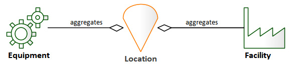
Figure 6.38 – Location-focused metamodel
The elements described thus far make up the bulk of the physical layer. Now, let's see how we can use these elements to provide some context around ABC Trading's physical infrastructure.
Putting the elements together for ABC Trading
As mentioned in previous chapters, ABC Trading has around 1,000 employees. Their operation is distributed among four different facilities and a fleet of trucks. The following diagram provides context around those facilities:

Figure 6.39 – ABC Trading facilities
The preceding diagram is an example of a context diagram. The intent is to show the major facilities at ABC Trading and their relationships. The diagram uses the facility, distribution network, and equipment element types. The primary link types used are the serving and assignment links.
As the diagram depicts, Lakeview Datacenter is assigned to each of the warehouses and serves the headquarters. Each truck fleet equipment element is part of a distribution network that serves its respective warehouse. Besides the new elements from the physical layer, there is something different about this diagram—something that we have yet to cover in this book: different ways to model dependencies.
Modeling dependencies in ArchiMate® 3.1
You may have noticed that the warehouse facility elements and the truck fleet equipment elements are nested inside of their respective network distribution elements. ArchiMate® 3.1 provides for two different means of representing aggregation and composition dependencies. You may choose to use the standard link type or a nesting relationship, as depicted in the following diagrams:

Figure 6.40 – Linking versus nesting examples
While the ArchiMate® 3.1 standard defines these two methods to mean the same thing, it's important to note that Sparx doesn't necessarily treat them the same. Establishing a link between two elements in Sparx, as in Figure 6.40, Linking Example creates a data element in the Sparx repository that holds information about the relationship that is independent of both the source and target elements being linked. In this case, Sparx does not know about the parent-child nature of the relationship.
On the other hand, in the case of Nesting Example, Sparx treats the Parent Element as a container to hold the child elements. In this scenario, however, no separate link data element is created in the repository, as we can see here:
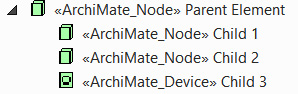
Figure 6.41 – Nested relationship
The importance of the difference between these approaches will become clear when we get to Chapter 11, Publishing Model Content.
Important Note
If you are unsure about which type of relationship to use, it's probably best to stick with a link type as you will have much more flexibility in refining information about the relationship.
The following ArchiMate® 3.1 technology diagram provides us a deeper look into a distribution network:

Figure 6.42 – Northwest distribution network
The preceding diagram provides a slightly deeper look into the northwest distribution network. It shows both the product types stored and customer service locations serviced by the distribution network. Note that Cherry Avenue Warehouse, Northwest Truck Fleet, and Northwest Region Distribution are the same elements that we created in Figure 6.39.
With two simple physical layer diagrams, we've provided an overview of all the relevant facilities, equipment, products, and locations involved in our business. Now, let's look at how we keep these facilities communicating through our network.
Modeling networks
In this section, we review the following element types and their relationships:

Figure 6.43 – Network-related elements
If you've been accustomed to communication network models produced in other model notations, your first impression of ArchiMate®'s coverage of the network may not be all positive. After all, there are only two elements and two link types in the ArchiMate® Technology Layer to represent a communication network. Other modeling languages include a plethora of elements to represent routers, switches, bridges, firewalls, and much more. They have links that represent specific aspects of a network, such as protocols, speeds, and connection types.
What may seem like a lack of coverage is not really a problem. The abstract nature of the technology device element type combined with the features and flexibility of Sparx provides a rich set of capabilities for network modeling in ArchiMate®. The details involved in establishing and maintaining a reliable communication network require specific skills. Just as we leave specific software design decisions to the software architect, we leave the specifics of communication network design to the network engineer. An enterprise architect rarely needs to specify much more than the capabilities of a communications network.
In this section, we will look at the ArchiMate® coverage of the communication network and how ArchiMate® can be applied to various network concerns at the enterprise level. First, let's look at what a network is.
The communication network element
According to section 10.2.7 of the ArchiMate® 3.1 specification, "A communication network represents a set of structures that connects nodes for transmission, routing, and reception of data." (https://pubs.opengroup.org/architecture/archimate3-doc/chap10.html#_Toc10045416)
The simplest network we can represent would connect two devices, as shown here:

Figure 6.44 – A simple communication network
When we use the term network in this section, know that we are referring to a communication network. We need to distinguish it from other types of networks, especially a distribution network, which is part of the physical layer described in the previous section. Networks are rarely as simple as the one shown in the preceding diagram. They are far more likely to connect hundreds or thousands of devices and require many different types of hardware and software to manage.
Notice that the preceding diagram uses a connection relationship to represent the network. This connection notation makes sense because networks connect devices. In many cases, there are literally cables and wires that connect one device to another. A communication network connector is a simple solid line with arrows on either end, as in the following diagram:
![]()
Figure 6.45 – Communication network connector notation
Using a communication network connector in Sparx is a little different than making other types of model connections. Most connections in Sparx require that you mouse-drag a connector from one element to another. When you release the mouse button, you are presented with a context menu asking for the type of connection to make.
In this case, however, you need first to indicate that you are making a specific type of connection by selecting Communication Network (Connector) from the toolbox. Then, when you mouse-drag a connector between elements, you should not see a context menu when you release the mouse button. The communication network connector should appear automatically, as depicted in the following screenshot:

Figure 6.46 – Using a Communication Network connector
If you receive a connection context menu when you release the mouse button, something went wrong.
Of course, connecting devices through a network means that each device has a path to every other device on the network. Using such a connection notation in a diagram could become problematic, however, when we want to depict many devices or nodes connected to each other via the network. The more nodes we add to the diagram, the more cluttered and confusing it becomes, as shown here:

Figure 6.47 – A cluttered network diagram
To alleviate this mess, ArchiMate® 3.1 also provides an element to represent a Communication Network, as shown in the following diagram:

Figure 6.48 – The communication network element
Using the Communication Network element is very effective at reducing clutter. The following diagram is a repeat of Figure 6.47, but we've used the Communication Network element rather than links:

Figure 6.49 – Using the communication network element
Using element notation also provides a means of documenting aspects of the network without needing to reference specific nodes on the network. The following diagram shows some of the devices and software that make up a communication network:

Figure 6.50 – Devices that aggregate a network
Using Sparx to model networks provides the added benefit of documenting and storing many other network attributes in the communication network element. In some cases, we use tagged values on the network element to hold various attributes of the network, as shown here:
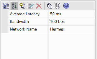
Figure 6.51 – Network attributes' tagged values
Next, we'll look at the communication network-focused metamodel.
Communication network-focused metamodel
The following diagram depicts the possible relationships of the Communication Network element:
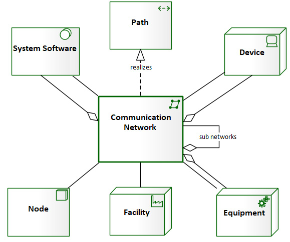
Figure 6.52 – Communication network-focused metamodel
There are three possible relationships with the Communication Network element. When an element needs to show that it connects to a network, we use a simple association relationship. If an element helps to make up a network, we use an aggregation relationship. The realizes relationship is discussed in the next section.
The path element
When your stakeholders are technical folks, especially network engineers, using a physical network view—as we have done so far—is often the best choice. What about non-technical stakeholders? They don't need the same level of detail, as such information is removed for the clarity of their viewpoint. Sometimes, even when our audience is technical folks, the details of a physical network view are not necessary.
Important Note
When details of an implementation are not necessary to communicate, it's almost always best to abstract those details away. Keep your audience focused on your point of your view.
Also, how would we represent the exchange of something other than data—say, physical items among facilities? ArchiMate® provides another way to depict a more abstract form of communication—the Path element and connector, as shown here:
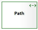
Figure 6.53 – The path element
According to section 10.2.6 of the ArchiMate® 3.1 specification, "A path represents a link between two or more nodes, through which these nodes can exchange data, energy, or material." (https://pubs.opengroup.org/architecture/archimate3-doc/chap10.html#_Toc10045415)
The following diagram depicts two nodes connected by a path connector:
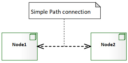
Figure 6.54 – Simple path between two nodes
The following example is more germane to our user-story exercises. In this view, the data center produces what is known as Picking Tickets and transmits them to each of the warehouses. A picking ticket tells a picker which items to place in a box for transport to a customer's location. In this view, the particulars of the communication network are not important:

Figure 6.55 – Transfer of picking tickets to warehouses
When used as an abstraction to a communication network, the relationship between the communication network and the path is a realization relationship, as depicted in the following diagram:
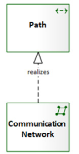
Figure 6.56 – Physical network realizes a path
A path can also be used to represent the transfer of energy, as in the following diagram:
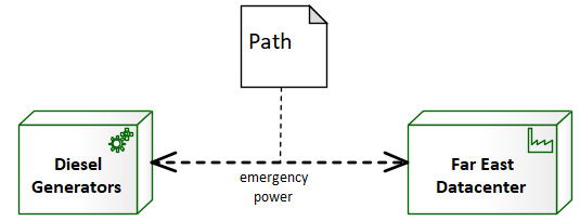
Figure 6.57 – Emergency power path
A path can be used to represent the transfer of physical elements such as products. The following diagram shows products being shipped from a warehouse to customer locations:

Figure 6.58 – Product shipment paths
Notice that details of how they are shipped are unimportant and thus not expressed.
Path element-focused metamodel
The logical connections that a path may make to other model elements are depicted in the following diagram:

Figure 6.59 – Path-focused metamodel
As you can see, the network modeling capabilities of ArchiMate® 3.1 are quite different from other network modeling languages. Traditional networking efforts often include huge diagrams with 15 different element types and lines, traversing across other lines and off the page. They are absent from ArchiMate®. Whether such models are necessary is debatable, but certainly not at the architecture level.
Summary
In this chapter, we have covered all active and passive structural elements in the Technology Layer of ArchiMate®. That's a lot to digest in one sitting. Hopefully, we haven't overwhelmed you.
To recap, we've learned how to model technology environments, communication networks, and physical environments. We also picked up some tips on using diagram layers and tag values in Sparx. Practicing the techniques presented here provides the skills necessary to communicate the most important aspects of your technology environment without losing your audience in the details. Using the features of a tool such as Sparx can help you do this while still maintaining the details necessary for implementation.
In the next chapter, we will cover the behavioral elements of the Technology Layer. We will also use some of what we've learned here to take a deeper look at ABC Trading's enterprise.