All computers have to have some form of input or output in their execution. This will be one of the following:
Neither input nor output — A box that does not do anything!
Input only — Those status reports for your manager that never get read.
Output only — Always talking but never thinking!
Input and output — A (hopefully) useful computer
This chapter discusses one method needed to allow for the input and output of data. There is usually a BIOS or software library that you can use that encapsulates the hardware known as the BSP (board support package), but if you are programming an application that requires direct port access, read on! For example, the communications API in Win32 does not give you time stamps or error status on each character received and some communication protocols require it.
Cameras typically input to a computer using memory in graphic frame grabbers just as a graphic display outputs using memory in graphic frame buffers, but the I/O (input/output) port is another method one can use to communicate with a computer. Network cards, serial communications, computer mouse, display controller on a graphics card, keyboard, etc., all use an input port, a "doorway," to get information into or out of a computer.
For example, pressing a key to type this document caused the little computer chip in my keyboard to decode the row and column of the keyboard matrix it was scanning, convert it to the corresponding value representing that scan code, and send it out that little wire or infrared port from my keyboard to my computer. There it arrived in an input port, causing an interrupt and letting my computer know there was something waiting to be read. Interested? Well, read on!
Mnemonic | P | PII | K6 | 3D! | 3Mx+ | SSE | SSE2 | A64 | SSE3 | E64T |
|---|---|---|---|---|---|---|---|---|---|---|
IN |
|
|
|
|
|
|
|
|
|
|
in | AL/AX/EAX/RAX, #8 | (Un)signed |
in | AL/AX/EAX/RAX, DX |
This instruction inputs an 8-, 16-, 32-, or 64-bit value from the specified 8-bit port (0...255), or an 8-, 16-, 32-, or 64-bit value from the 16-bit port (0...65535) specified by the DX register.
Flags | O.flow | Sign | Zero | Aux | Parity | Carry |
|---|---|---|---|---|---|---|
- | - | - | - | - | - |
Flags: None are affected by this opcode.
When working a legacy VGA graphics display there is sometimes a need to synchronize your code to the VBlank (vertical blank). An example would be using DirectX under Win95. If we have animation running at a frame rate in a dual frame environment, there is no clean way to wait for the VBlank on frames that do not need to flip because it is too easy to miss them as DirectX only waits for the leading edge of the VBlank. Note that in a multithreaded environment there is a chance that we could get preempted by another thread, causing us to miss the VBlank. We could also be preempted just after detecting it, causing us to miss it entirely.
VGA_STATUS   = 03dah       ; VGA Status address
VSYNC_MASK   = 00001000b   ; VSync bit

        mov    edx,VGA_STATUS
        mov    ah,VSYNC_MASK

Loop:   in     al,dx       ; Get VGA status
        test   al,ah       ; Is VSync bit set?
jz Loop ; Jump if notMnemonic | P | PII | K6 | 3D! | 3Mx+ | SSE | SSE2 | A64 | SSE3 | E64T |
|---|---|---|---|---|---|---|---|---|---|---|
OUT |
|
|
|
|
|
|
|
|
|
|
out | #8, AL/AX/EAX/RAX | (Un)signed |
out | DX, AL/AX/EAX/RAX |
This instruction outputs an 8-, 16-, 32-, or 64-bit value to the specified 8-bit port (0...255), or an 8-, 16-, 32-, or 64-bit value to the 16-bit port (0...65535) specified by the DX register.
Flags | O.flow | Sign | Zero | Aux | Parity | Carry |
|---|---|---|---|---|---|---|
- | - | - | - | - | - |
Flags: None are affected by this opcode.
The following two functions are snippets from the examples later in this chapter.
;  Initialize the parallel port
;
;  void PPortInit(void)

PPortInit proc  near
       mov    edx,PPort             ; Get base address
       add    edx,iPIO_DCR          ; Add offset
       in     al,dx                 ; Get control bits

       or     al,iPIO_DCR_DIR       ; Set direction bit to tristate
                                    ; For bidirectional access
       out    dx,al                 ; Do it!
       ret
PPortInit endp


;  Serial Out ah=char

Sout   proc   near
       mov    edx,ComAdr
       add    edx,5

$S1:   in     al,dx                  ; Get status
       test   al,00100000b           ; Twx holding register empty
       jz     $S1                    ; Jump if still has character

       mov    al,ah                  ; Get character
mov edx,ComAdr
out dx,al
ret
Sout endpinsb | (Un)signed | 8 | |
insw | 16 | ||
insd | 32 | ||
ins | byte ptr es:[edi], dx | 8 | |
ins | word ptr es:[edi], dx | 16 | |
ins | dword ptr es:[edi], dx | 32 |
This instruction inputs an 8-, 16-, or 32-bit value from the specified 16-bit port (0...65535), copies it to the destination string referenced by ES:[EDI], and advances the EDI register based upon the setting of the Direction flag and the data size. It is similar to a STOSx instruction except that the data is read from the port instead of the AL/AX/EAX register and both are written (stored) to the string. This is actually a DMA transfer from an input port but is really only efficient if trying to move more than 64 bytes.
Flags | O.flow | Sign | Zero | Aux | Parity | Carry |
|---|---|---|---|---|---|---|
- | - | - | - | - | - |
Flags: None are affected by this opcode.
Mnemonic | P | PII | K6 | 3D! | 3Mx+ | SSE | SSE2 | A64 | SSE3 | E64T |
|---|---|---|---|---|---|---|---|---|---|---|
OUTSB |
|
|
|
|
|
|
|
|
|
|
outsb | (Un)signed | 8 | |
outsw | 16 | ||
outsd | 32 | ||
outs | dx, byte ptr ds:[esi] | 8 | |
outs | dx, word ptr ds:[esi] | 16 | |
outs | dx, dword ptr ds:[esi] | 32 |
This instruction outputs an 8-, 16-, or 32-bit value from the source string referenced by DS:[ESI], copies it to the 16-bit port (0...65535), and advances the ESI register based upon the settings of the Direction flag and the data size. It is similar to a LODSx instruction as data is read (loaded) from a string but with the exception that the data is written to the port instead of AL/AX/EAX register. This is actually a DMA transfer to an output port but is really only efficient if trying to move more than 64 bytes.
Flags | O.flow | Sign | Zero | Aux | Parity | Carry |
|---|---|---|---|---|---|---|
- | - | - | - | - | - |
Flags: None are affected by this opcode.
AUART (universal asynchronous receiver/transmitter) these days has a FIFO (first in, first out) buffer typically 16 bytes in length. You could send this in a variety of ways. If you know the FIFO is empty, you can have some sort of unrolled loop:
i=0
REPEAT 16
mov al,[esi+i]
out dx,al
i=i+1
ENDM
add esi,16...or use a string function:
mov ecx,16 rep outsb ; outs dx,byte ptr [esi]
...keeping in mind the >=64 repeat needed to be efficient. Because of this, the unrolled loop is better.
To get information about the serial and parallel ports of your PC, visit the National Semiconductor web site at www.national.com and download the following PDF data sheets.
16550 UART — At the time of this printing this was the PC16550D, which is a UART (universal asynchronous receiver/ transmitter) used for serial communications.
NS486SXF processor — This is a 486 embedded processor, but we're really only interested in two sections: "3.4.2 The IEEE 1284 Bi-directional Parallel Port" and "3.4.5 The Serial UART Port."
Both of these are excellent references for all the I/O information necessary for communicating directly with the serial and parallel ports on your PC.
Normally you do not need to access this port, but what if you have a specialized application that is not communicating with a printer but something else, like a parallel communications device or a dongle (hasp). What if your PC is in reality an embedded system where it runs a display in a Gazebo and as such has no mouse or standard keyboard, but merely a couple of buttons for advancing through a slide presentation. It just powers up and runs an advertisement or is a slot machine using a NLX motherboard or some other embedded device, not necessarily a PC. What if it can be signaled through communications to play something else? What if this same device needs a watchdog to know it failed or dip switches for some kind of addressing or feature selection just by setting some switches? Maybe it drives an LCD (liquid crystal display). (Remember, no keyboard or maybe it drives one directly in parallel.) Or maybe you are just itching to build some hardware to plug into your computer.
Datel used to manufacture a special parallel interface card for the PC. This was designed to connect via a parallel cable to a Game Shark made by InterAct and allowed a PC to be able to connect to various consoles. Hackers built software drivers and tools that allowed them to develop games for some of those consoles such as the old Sony Playstation.
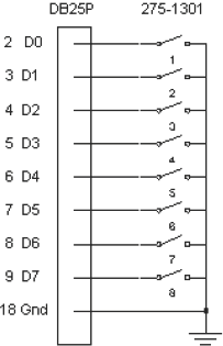
Our little experiment lets us tinker with reading dip switches plugged into the parallel port. You can buy an eight-bank dip switch at your local Radio Shack store (part #275-1301).
The PC parallel port specifications state that:
DB25P | Description | |
|---|---|---|
| 2 | DO |
| 3 | D1 |
| 4 | D2 |
| 5 | D3 |
| 6 | D4 |
| 7 | D5 |
| 8 | D6 |
9 | D7 | |
18-25 | GND |
DB25P | Description | |
|---|---|---|
| 1 | ~Strobe |
| 10 | ~ACK |
| 11 | ~BUSY |
| 12 | PE |
| 13 | SLCT |
| 14 | ~AUTOFEED XT |
| 15 | ~ERROR |
| 16 | ~INIT |
| 17 | ~SLCT IN |
First we need to initialize the port that we will consider LPT1, which uses a base address of 378h. We should note that the typical parallel port is set up to be unidirectional and not bidirectional, which means that we normally can only write to the data lines, not read from them. In our initialization function we set the bit, which causes our eight data bits to tri-state, thus making them bidirectional.
Parallel Port Base Address
LPT1 | LPT2 |
378h | 278h |
Note
Old monochrome cards used 3BCh for their parallel port.
iPIO_DCR = 2 ; Device control register
iPIO_DCR_DIR = 00100000b ; 20h = direction bit
PPort dd 378h ; Using LPT1 for base address
; Initialize the parallel port
;
; void PPortInit(void)
PPortInit proc near
mov edx,PPort ; Get base address
add edx,iPIO_DCR ; Add offset
in al,dx ; Get control bits
or al,iPIO_DCR_DIR ; Set direction bit to tri-state
; For bidirectional access
out dx,al ; Do it!
ret
PPortInit endp
; Read switches from the parallel port
; Note: Only lower 8 bits will be set, upper bits clear
;
; uint32 PPortRead(void)
PPortRead proc near
xor eax,eax ; eax=0
mov edx,PPort ; base address is data port
in al,dx ; get 8 bits from port
ret ; return value in EAX
PPortRead endpLets look at the C code calling our parallel port functions:
uint 32 n;
PPortInit();
n = PPortRead();
printf("switches =0x%x", n);You will note that the logic is inverted so when a switch is off, thus leaving the circuit open, a logical 1 is produced, but if the switch is on, thus closing the circuit and shorting the input to ground, a logic 0 occurs. You can think of this as upside-down binary. To solve for this just insert the following:
PPortRead proc near
xor eax,eax ; eax=0
mov edx,PPort ; base address is data port
in al,dx ; get 8 bits from port
xor eax,000000ffh ; Flip switch bits
ret ; return value in EAX
PPortRead endpThe second XOR just before the RET will flip the switch bits so off=0 and on=1. This will help make life simpler.
I need to mention that there is one little problem with the circuit. Although the specifications of the data port consider the tri-state (float) condition to be a logical 1 until pulled to ground, some computers float with voltage a little low so they are not considered a logical 1. And as such the switches are thought of as always closed. The parallel port has no (+5v) source and as such one of two things need to be done: an external one supplied (battery, etc.) or one leached off all the other control signals, creating a pseudo 5-volt supply. Those signals would obviously have to have their output signals in a high state. That voltage would then need to be connected in series to a pull-up resistor attached to one side of each of the switch terminals, thus giving them a logical high signal. The other switch terminal is connected to ground, so when the switch is closed it pulls the signal low.
DOS had a BIOS function that allowed you to print a TTY message to the output device. But what if you are running an embedded operating system like pSOS or running under Win32? The printf() and TTY functions do not really go anywhere, especially if you are running a full-screen DirectX application. Well, you could always do a kind of printf() out the serial port to a smart terminal. Did you know you could pick up old PS/2 computers from places like Goodwill for $9-$50 still in running condition and looking in pretty good shape? I call them throw-away computers. When running an old DOS version of ProComm, they work great. When they break, you throw them away! The lap-link cable to connect your two computers will probably cost you more than the computer. To reduce my desk footprint I use a very small 9" VGA monochrome monitor and a very small 83-key keyboard. Unfortunately, they are not as cheap. I use a logging library that I recreate for every company I work for. In it I do a single log write and it can optionally go to a disk file, a Notepad window, and/or a particular serial port at a specified baud rate. In Win32 I use the CommAPI so it'll work in all the Win32 platforms, but the following will only work in Win95, DOS, or Linux.
Of course, other operating systems such as embedded systems that allow Real Mode or security access to the I/O ports and interrupts, will work as well. To simplify it I have hard-coded the base address and IRQ information to COM1, but it is really a snap to do a table lookup during the initialization function to set things up and save the actual information needed for the send function.
The PC serial port specifications state that:
DB9S | DB25S | Description | |
|---|---|---|---|
| 1 | 8 | CD (Carrier Detect) |
| 2 | 3 | RCV (Receive Data) |
| 3 | 2 | TWX (Transmit Data) |
| 4 | 20 | DTR (Data Terminal Ready) |
5 | 7 | GND | |
| 6 | 6 | DSR (Data Set Ready) |
| 7 | 4 | RTS (Request To Send) |
| 8 | 5 | CTS (Clear To Send) |
| 9 | 22 | RI (Ring Indicator) |
Serial Port Table
COM1 | COM2 | COM3 | COM4 | COM5 | COM6 | |
|---|---|---|---|---|---|---|
BaseAddr | 3F8h | 2F8h | 3E8h | 2E8h | 368h | 268h |
IRQ Interrupt | 0Ch | 0Bh | 0Ch | 0Bh | 0Ch | 0Bh |
IRQ Mask | 0EFh | 0F7h | 0EFh | 0F7h | 0EFh | 0F7h |
INTMSK = 21h ; Mask register port #
ComAdr dd 3f8h
ComIO db 0ch
ComMask db 0efh
OldMask db 0 ; Old interrupt mask
; bool ComInit(uint nBaud);
ComInit proc near
push ebp
mov ebp,esp
push ebx; Disable 8259 interrupt for IRQ
in al,INTMSK ; Get IRQ bits
mov ah,ComMask ; Clear interrupt bit
mov OldMask,al ; Save them
not ah ; Flip mask into strip
or al,ah ; Disable bit
out INTMSK,al ; Set IRQ bits
; Disable UART interrupts
mov edx,ComAdr ; Port address
inc edx ; (+1) .IER - Interrupt Enable
mov eax,0 ; disable UART interrupt bits
out dx,al ; Disable UART interrupts
; Disable all handshaking
add edx,3 ; (+4)
out dx,al ; Disable all handshaking
; Set up for appropriate protocol
dec edx ; (+3) .LCR - Line Control
in al,dx ; Get Line Control
or al,10000000b ; Set Divisor Latch Access
out dx,al
; Calculate baud rate divisor
mov ecx,[ebp+8]
mov edx,0
mov eax,1843200/16
div ecx
; Write baud rate
mov edx,ComAdr ; Port address
out dx,al
inc edx ; (+1)
mov al,ah
out dx,al
; Bits per char and parity
mov al,00000011b ; 8 bits no parity
add edx,2 ; (+3) .LCR
out dx,al; Set handshaking lines
inc edx ; (+4) .MCR
mov al,00001111b
out dx,al
mov eax,1 ; Success
pop ebx
pop ebp
ret
ComInit endp
; Serial Out ah=char
Sout proc near
mov edx,ComAdr
add edx,5
$S1: in al,dx ; Get status
test al,00100000b ; Twx Holding Register Empty
jz $S1 ; Jump if still has character
mov al,ah ; Get character
       mov    edx,ComAdr
       out    dx,al
       ret
Sout   endp
; void ComStr(byte *pStr);
;
; Write String
ComStr proc near
push ebp
mov ebp,esp
mov ecx,[ebp+arg1] ; Get string pointer
mov ah,[ecx] ; Get a character
inc ecx
test ah,ah
jz $xit ; string terminator?
$1: call Sout ; Write a character
mov ah,[ecx] ; Get a character
inc ecx
test ah,ah ; string terminator?
jnz $1 ; jump if not$xit: pop ebp
ret
ComStr endpLet's look at the C code calling our serial port functions:
ComInit(19200);
ComStr("The quick brown fox

");
Since the port number is hard coded to simplify this example, the code is initialized but only the baud rate can be set. Thereafter, zero delimited character strings are written to that serial port through the call to the ComStr() function. In this elementary form, very simple.