Smart Grid Network Architecture
Information in this chapter:
Now that the term “Smart Grid” has been defined, it’s important to understand how the Smart Grid is architected. Unfortunately, the “Smart Grid” is not a single easily defined system, but rather an extremely complex interconnection of multiple systems. Many of these individual systems are also complex and built upon newer, more intelligent components of generation, transmission, distribution, and metering. Understanding the individual components—and how they are interconnected and deployed—will help to understand how vulnerable or secure a Smart Grid is.
Architecturally, the Smart Grid can be thought of as a modernization of the existing generation, transmission, distribution and metering infrastructures that have delivered electricity to businesses and residences for decades. The components themselves—meters, voltage regulators, transformers, breakers, and so on—serve the functions as always. However, by becoming “smart,” these components can now provide more information about their respective tasks and communicate that information to other centralized systems where it can improve efficiency and reliability through automation. There are also entirely new systems designed to enhance the grid and provide enhanced features and capabilities. These include measurement systems (such as synchronized phasor measurement systems), energy management systems, and even meteorological and environment monitoring systems—all of which provide valuable information with which to enhance or automate the production, delivery, and utilization of energy. However, it’s important to remember that information on its own does not a Smart Grid make. Reliable communication of real-time information is the key. Therefore, to benefit from this new level of intelligence, it is also necessary to build interconnectivity between the various systems and services so that the data can be collected and utilized. If you think of the Smart Grid in human terms, the increased monitoring and measurement systems might equal the eyes, ears, and nose as well as the sensory receptors of the brain. The communication systems might equal the mouth, vocal chords, and the ears, as well as the communicative center of the brain. Finally, the automation systems might equal the arms, hands, and fingers, as well as the motor functions of the brain. The analogy seems trite, but serves a purpose: to highlight the common participation of the brain. This illustrates the underlying concern about Smart Grid cyber security: manipulation of the Smart Grid’s brain allows manipulation of all aspects of measurement, communication and automation.
Ultimately, the brain of the Smart Grid exists to make energy delivery efficient and cost-effective. This requires upgrading the existing infrastructure—from generation through T&D to metering—to a digital anatomy of microprocessors, software, and network communication channels. The various components of the Smart Grid are evolving to provide:
• Monitoring and Measurement: More intelligence at each device.
• Network Connectivity: Communications between devices.
• Automation: Closed-loop process control capability within and between key systems.
Unfortunately, intelligence, communications, and automation also represent a significant cyber security challenge. The grid, through this evolution, has become accessible digitally. The manipulation of any one of these capabilities can affect the entire Grid. A manipulated reading of a synchrophasor might initiate an unnecessary load shed. The interruption of the metering network might prevent an end user from being billed (and in turn, the utility from getting paid!). The manipulation of automation systems within a substation might cause a loss of service to an entire community.
Even more unfortunate is that with this evolution of capability, there are also new, strong motives for a malicious actor or attacker to target the cyber assets of the Smart Grid. Primary motives include the theft of information and the manipulation of automated systems for purposes of disruption or sabotage.
Perhaps, one of the largest security concerns of the Smart Grid, however, supersedes the individual systems of measurement, communication, and control. It is the sheer interconnectedness of it all. Intelligence and communications and automation are simply the means to an end: the real “Smart Grid” is built upon many systems that leverage these mechanisms. Advanced metering leverages information from distribution management systems and distribution control (SCADA) systems. Transmission systems leverage information from generation SCADA. Systems ranging from customer management to demand-response systems and from automated dispatch servers to phasor data concentrators all interconnect, creating an unprecedented playground for a malicious actor or attacker. The attack surface is large, the attack vectors are many, and once inside the Smart Grid, an attacker can migrate to almost any system from the generator to the meter to inside the home (and into your refrigerator).
Starting at generation, and moving through transmission, distribution, and metering, each of these systems will be explored to identify how they operate, looking at the types of devices utilized by each and identifying the specific risks and vulnerabilities of those devices.
Bulk and distributed generation architectures
The first step in understanding Smart Grid architecture is a step away from what most people think of as “the grid,” to discuss the architecture of energy generation. This is because energy generation is an important component of the Smart Grid. While it seems that a Smart Grid discussion should focus on the transmission and distribution infrastructure, energy generation systems are tightly integrated into T&D intelligence and automation, with many Smart Grid systems—such as demand-response systems—directly leveraging the generation infrastructure. A discussion of generation systems is also important as the T&D infrastructure evolves to support field generation and even in-home generation. Distributed generation at a micro level—inbound power from small wind and solar farms, residential batteries, electric vehicles, etc.—further integrates the complexities and risks of generation systems into the Smart Grid.
Finally, discussing generation architecture is important because of the relative maturity of the two markets: While “the grid” is evolving into something more connected and automated, electrical generation has been automated for many years. Generation architecture, therefore, provides an excellent frame of reference around any discussion of Smart Grid security.
For this reason, the architecture described herein will begin with a discussion of generation systems before we move on to transmission, distribution, and metering. Understanding generation architecture—and the cyber security risks and vulnerabilities of that architecture—is an important first step to understand cyber security for the Smart Grid, as many of the concepts here apply to the evolving grid infrastructure as well.
Types of electrical generation
Electric generation sources include several distinct mechanisms, built around the specific fuel used to create electricity—for example, a hydro-electric plant uses water, a nuclear facility uses controlled nuclear fission, fossil fuel facilitates use oil or natural gas, solar uses the power of the sun, wind farms are driven by wind turbines, etc. Each system represents its own vulnerabilities that are inherent in their designs, and therefore each represents its own unique security challenges.
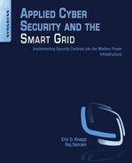
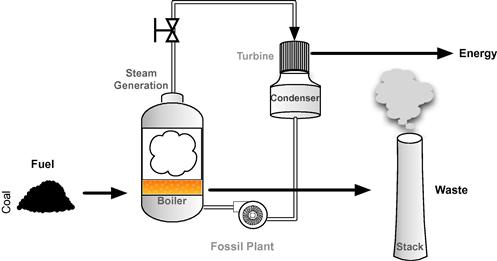
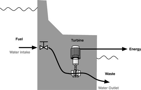
A fossil fuel generation system represents several processes that aren’t present in generation systems using water, wind, or sunlight as fuel. Fossil fuels must be conditioned, fed into a burner, combusted to generate steam, which then drives a turbine to generate electricity (Figure 2.1). Condensers are required to reclaim water to drive continued steam generation. In contrast, solar generation can convert sunlight directly to electricity. Solar cells are used to generate direct-current electricity, which is collected for conditioning (conversion from direct to alternating current) and transmission (Figure 2.2). Solar power can also be used to power boilers for steam generation, replacing the coal fuel and burners of Figure 2.1 with solar energy.
Functionally, most electrical facilities operate in the same general process:
• Fuel is utilized to create raw “kinetic” energy.
• Raw “kinetic” energy is converted to electricity, typically using a turbine generator (or, in the case of solar, photoelectric cells).
• The electricity is collected, transformed into the correct voltages and frequencies, and either stored (in the case of direct current with batteries) or given to the T&D system.
At the same time, there are other important processes that are of concern. These include the following:
• The storage, transportation, and utilization of fuel.
• The storage, conditioning, and utilization of boiler feed water.
For each function, industrial control components are used to automate a process loop, and together they make up the larger distributed control system that consists of many such process loops.1Figures 2.1–2.5 illustrate the energy generation process across industries, distinguished by fuel. In each functional system the devices, architecture and logic differ slightly.
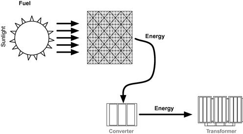
Like solar power, wind turbines represent a much simplified version of electric generation: While a turbine is used to create electricity, it is driven directly by the kinetic energy of the wind, eliminating the need for boilers, steam, condensers, and fuel.
Note that in “clean” or “green” energy systems such as hydro (Figure 2.4), solar, and wind, the necessity to supplement generation operations with auxiliary systems—especially those involving fuel and waste handling—is reduced. For example, the fuel of hydro-electricity is water, and the waste material of hydro-electric generation is water. The fuel is naturally occurring, and the byproduct of generation is not harmful. The “waste” simply needs to be delivered appropriately back into the environment. This simplification of operations is a natural byproduct of using cleaner energy sources and is one of the many benefits driving the adoption of green energy.
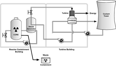
Clean, renewable energy has advantages as well as disadvantages. A small solar PV (photovoltaics or direct solar to DC electricity) is renewable, produces essentially no waste, but might offer a peak output of only 3 kV.2 A single nuclear reactor, though significantly more complex (Figure 2.5), will typically output in excess of 1000 MW.3 The sheer capacity of generation, combined with the nature of the fuel, processing, and waste also leads to increased regulations. Not surprisingly, nuclear generation facilities are heavily regulated, and security (both physical and cyber) is a primary concern among plant operators.
Generation system architecture
Regardless of the type of generation facility, there are common concepts around information generation, utilization, and automation that are used heavily within the facility. By examining the specific areas that are vulnerable to potential exploitation, we can start to identify how information and automation systems might be attacked or manipulated by a malicious actor.
Some general areas of risk have been illustrated in Figure 2.6. Basically, any system that is controlled by a microprocessor or that is controlled by any device that contains a microprocessor and an operating system can be compromised. The few examples illustrated here are as follows: the mechanism(s) used to feed fuel into the burner; the mechanisms of the burner itself that control rate of combustion, regulate temperature via steam pressure, etc.; the mechanisms used to control the intake and flow of water/steam that is used to drive the turbine; the turbine generator; and the mechanisms used to transform the generated energy to the appropriate voltages and frequencies for transmission and distribution. While the accessibility to these various mechanisms will vary, the manipulation of any one mechanism can influence the generation process as a whole.
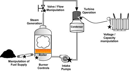
Figure 2.7 takes this same concept and illustrates it in greater detail, in order to further explore the ways in which a generation facility might be subject to a cyber attack. Using a coal-fired steam generator as an example, we can see that the functional mechanisms that are generalized in the Figure 2.6 map to specific designs consisting of several controllers, inputs, and outputs. For example, the fuel supply is an automated system consisting of a hopper and conveyor mechanism, while the generation itself consists of an interconnected system of burner, steam turbine, and coolant systems. There are sensors (inputs) that measure the available fuel in the hopper, as well as sensors that indicate the speed of the conveyor, the amount of fuel in the burner, the pressure in the steam system, the speed of the turbine, and many other inputs that are not illustrated here. There are also controls (outputs) that react to these inputs, such as the fuel pulverization motors, the fuel conveyor, the burner within the steam boiler, and various pumps and valves which control the pressure and rate of both the steam and coolant water.
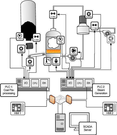
Corresponding with this architecture, of course, is the specific controller logic used to automate each specific process loop. In this example, we look at two specific process controllers: labeled PLC 1 and PLC 2 in Figure 2.7. PLC 1 is a modular PLC consisting of I/O to the process devices, a processing module to store and execute control application, and a network interface card for Ethernet connectivity to the SCADA network, including basic control via process-specific HMIs as well as a SCADA server to manage the entire generation process. PLC 1’s I/O is used for fieldbus connectivity to coal preprocessors and to the conveyors that feed the burner facility with the newly pulverized coal, and HMI 1 provides local control of coal pulverization and delivery.
PLC 2 is also a modular PLC, whose I/O connects to devices that make up the burner and energy generation processes, and with specific logic used to control those processes. Again, Ethernet is used to connect PLC 2 to the SCADA network, via which HMI 2 and the central SCADA server are connected. PLC 2’s I/O is used for fieldbus connectivity to the burner, steam regulation, and turbine systems that generate electricity, and HMI 2 provides local control of these processes.
The two process loops in this example are as follows: PLC1 reads volume of the fuel supply from the hopper (1) of the coal pulverizer. When coal is available, it is fed through an opening (2) at a controlled rate through grinders (3) that pulverize the coal. The pulverizer can be set to grind to various granularities to accommodate different burners: In this case, it is set to a fine powder. When fuel is available (1) and the grinder is operating (3), the feed conveyor (4) delivers the powdered coal to the burner. The powder is deposited onto a conveyor that feeds the fuel burner. PLC 2 controls the burner and steam generation: engaging the burner (8) in response to the temperature (6) and regulating the flow of steam using valve (5) and pump (9) in response to readings from pressure sensor (7). PLC 2 also reads the speed of the turbine (10) to adjust the flow of coolant water using another series of valves (11) and pumps (12).
Generation system security concerns and recommendations
While the control processes used in this generation facility are fairly simple, manipulation of any one process could impact the entire system. Looking at Figures 2.7–2.9, we can see several areas that are of concern. For example:
• The individual programmable logic controllers can be manipulated, overwriting the legitimate control application with new code designed for a malicious purpose.
• PLC, HMI, or SCADA systems could be used to establish a command and control (C2) channel outside of the control room, to enable data theft and/or further attacks remotely.
• The HMI could be accessed and used to manually control specific aspects of the control process.
• A man-in-the-middle attack inline on the Ethernet network could alter or misrepresent I/O values to the HMI (read values) and PLC (write values).
Any of these attacks would expose all aspects of the automated processes (in this case, pulverization and generation) to a hacker. The consequences of this exposure could include any or all of the following:
• Steal data about the process or about production.
• Slowing or interrupting the supply of fuel, impacting the efficiency of the burner or potentially taking the burner offline which would reduce steam flow to the turbine eventually causing it to trip and stop producing electricity.
• Increasing the supply of fuel, causing over firing of the burner or possible interference with the injection of fuel into the burn chamber, potentially taking the burner offline (again resulting in a turbine trip).
• Limit the flow of steam while increasing pump pressure, causing unintended strain on the pump (as it attempts to raise pressure beyond levels allowed by mechanical relief valves or blowdown valves) and increasing the chances of a pump failure.
• Increase the flow of steam to overrun the turbine.
• Misrepresent the measurements of any of the above inputs to hide the breach from human operators.
• Misrepresent otherwise accurate measurements from non-altered inputs, to trick the human operator into mal adjusting an output.
• Crash the HMI creating a loss-of-view and effectively disabling basic control within the plant.
• Crash the PLC creating a loss-of-control situation that disables supervisory control while locking the process in its current state.
Without attacking the PLC directly, an attacker can still obtain control and manipulate a process, using the HMI systems.
• The communications to or from the SCADA server and the controller’s I/O could be manipulated, either:
- To alter the existing programmable logic, create and implement new logic, alter HMI interfaces, or change set points in order to maliciously affect the IS.
- To alter or manipulate the data being reported back to the SCADA server, to trick the operator into making a change that is (unintentionally) out of spec.
• The communications to or from the controller’s I/O and the field devices could be manipulated, either:
- On the network via inline intrusion, tapping, etc. Network attacks could include man-in-the-middle exploits, network replay, or denial-of-service attacks.
- Manipulation of the fieldbus commands given by the controller, so that the field devices operate out of spec.
- Manipulation of the data produced by field devices, tricking the controller into operating in an unauthorized manner despite being functionally within specification.
Exploiting the controllers
The controllers (PLC 1 and PLC 2) shown in Figure 2.7 are fictional examples of modular logic controllers consisting of device I/O, network I/O, and automated control logic. PLC vendors offer a wide range of products that include controllers, some of which are built using common hardware and a commercially available operating system (e.g. Windows), while many utilize an embedded operating system (e.g. embedded Windows) or a real time operating system (e.g. VxWorks). Network connectivity to SCADA servers is almost ubiquitously via Ethernet and TCP/IP, exposing the PLC to a routable network. At the same time, the device I/O is typically a fieldbus protocol (also commonly running over Ethernet, although serial bus protocols are still widely used). This makes the PLC potentially vulnerable: It has many available network interfaces and a commercial OS, and therefore, an attacker can theoretically gain access via the network and exploit a known OS vulnerability. As with any computer operating system, if new and patched appropriately, these controllers may be more secure. However, for the sake of this example, we will assume that they are running older code revisions.
Note that most of these threats involve the manipulation or alteration of the process logic. As with any logic that executes in a loop, new code could easily be inserted at any point to cause that process to stall. Furthermore, once network access has been obtained, standard engineering and configuration tools could be used to modify various ICS components. At the 2011 Applied Control Solutions Conference in Washington DC, Ralph Lagner presented a 14-byte Siemens Step 7 routine that would, at a given time, put a PLC into an endless loop, bypassing the intended ladder logic and essentially fixing the process into whatever state it was in when the 14-byte payload executed.5 This highlights what was first exemplified by the “St****t” malware that manipulation of PLC logic is not limited to the alteration of existing logic, but can be used to introduce entirely new logic, replacing or appending legitimate code to almost any end. At a high level, logic manipulation can result in the following:
• Manipulation of the intended process. Examples might include altering set points, timing, or other variables without otherwise changing the nature of the process.
• Insertion of new process commands. Examples include the aforementioned “logic time bomb,” manipulation of I/O, etc.
• Removal of process commands. Examples include process alterations to bypass or override critical steps of a process and to sabotage the process or bypass safety.
• Exfiltration of process commands. Examples include the theft of a manufacturing “blueprint”—essentially stealing the target’s intellectual property.
By looking at the logic in our steam generation example, we can see exactly how these threats could materialize. The logic of PLC 1 is simple: While there is a supply of fuel and demand for fuel (based on readings from the burner), the fuel pulverizer processes coal through a manipulation of a feed valve and a grinding motor and delivers powdered coal on to a conveyor that delivers the fuel at a controlled rate (based on readings from the pulverizer and the burner) to the burner. It can be seen how manipulation of this logic could impact the fuel delivery processes:
• Manipulation of coal pulverization to introduce unsuitable fuel onto the conveyor.
• Manipulation of pulverized coal delivery to introduce too little or too much fuel to the conveyor.
• Manipulation of the conveyor to deliver fuel too quickly or too slowly to the burner.
• Misrepresentation of available fuel levels, causing the process to run without fuel, or to stop running when there is fuel.
• Combinations of the above manipulations to alter or sabotage the process.
• Introduction of malware to the process to lock the process into the manipulated state.
• Disabling of SCADA connectivity to prevent remote management or remediation of the incident.
The logic of PLC 2 is similarly based upon measurements and reactions to those measurements: The burner combusts fuel to reach optimum temperature within the boiler (determined by temperature readings within the burner), to boil water into steam. Water is pumped into the boiler as needed to produce steam. The steam is moved at a given rate (based upon pressure of the steam lines, which is controlled by valves) to drive a turbine, which generates electricity. A condenser then converts the steam back into water using a regulated cooling system, for reuse by the boiler. In this example, it can be seen how manipulation of this logic could impact the burner and steam generation processes:
• Manipulation of temperature readings to cause under or over burning.
• Manipulation of pressure readings to cause unsafe steam pressure levels.
• Manipulation of release valves to prevent safe bleeding of excess pressure.
• Manipulation of available water to the steam system, causing failures in the boiler or turbine.
• Manipulation of available water to the coolant system, preventing adequate condensation and causing overheating or other damage to the turbine.
• Manipulation of turbine sensors to prevent adequate flow of steam or coolant.
• Misrepresentations of any input or output values to HMI or SCADA, to trick human operators into making errors.
• Combinations of the above manipulations to further alter or sabotage the process.
• Exfiltration of process data to report energy production levels to a malicious actor.
• Introduction of malware to the process to lock the process into the manipulated state.
• Disabling of SCADA connectivity to prevent remote management or remediation of the incident.
Network attacks
While the controllers and other devices are likely targets for attack, industrial control environments possess many inherent network-based vulnerabilities. Fieldbus protocols, whether running over legacy serial or new Ethernet transport, represent a security risk in industrial control environments. These protocols—DNP3, Modbus, PROFIBUS/PROFINET, CIP, and others—are ultimately designed around a common paradigm of request and respond. Each protocol is designed for a “master” device such as an HMI to send commands to subordinate “slave” devices such as a PLC to retrieve data (reading inputs) or instigate control (writing to outputs). Because many of these protocols lack authentication, encryption, or other basic security measures, they are ripened for network-based attacks, allowing a malicious actor or attacker to utilize the “request and respond” system as a mechanism for “command and control” like functionality.1 Specific security concerns common to most industrial control protocols include the following1:
- Network or transport errors (e.g. malformed packets or excessive latency) can cause protocol failure.
- Protocol commands may be available that are capable of forcing slave devices into inoperable states, including powering-off devices, forcing them into a “listen only” state, disabling alarming.
- Protocol commands may be available that are capable of restarting communications and otherwise interrupting processes.
- Protocol commands may be available that are capable of clearing, erasing, or resetting diagnostic information such as counters and diagnostic registers.
- Protocol commands may be available that are capable of requesting sensitive information about the controllers, their configurations, or other need-to-know information.
- Most protocols are application layer protocols transported over TCP; therefore it is easy to transport commands over non-standard ports or inject commands into authorized traffic flows.
- Protocol commands may be available that are capable of broadcasting messages to many devices at once (i.e. a potential DoS).
- Protocol commands may be available to query the device network to obtain defined points and their values (i.e. a configuration scan).
- Protocol commands may be available that will list all available function codes (i.e. a function scan).
These inherent vulnerabilities make network-based attacks very feasible. Simple injection of malicious protocol commands provides control over the target process, while “bit flipping” legitimate protocol traffic can alter information about a process as well as disrupt the legitimate controls that are in place over that process. A man-in-the-middle attack could provide both control over a process and misrepresentation of data back to operator consoles.
Data manipulation
• The concept of data manipulation has recurred throughout this chapter because of important role that “data” play in the overall automation process and because the alteration of that data can either directly or indirectly manipulate that process. “Data” here represent the values of the generation facility—the specific inputs and outputs used by the logic of the control applications. It is used within the controllers such as the PLC, but also reported to HMIs and SCADA consoles, where it is consumed by a human operator. Manipulation of these values can influence all aspects of automated production, distribution, safety, and reliability.
• Showing a human operator misleading values from the plant could cause the operator to override the (legitimate) automation logic, effectively sabotaging their own process. While the operator’s intentions are good, they are tricked into action through the dissemination of false data.
• Manipulating values used by other controllers could prevent supplementary systems—potentially including protection systems—from behaving properly. For example, if an alarm is supposed to trigger at a certain boiler temperature, the alteration of that set point from 400 ˚F to 500 ˚F could prevent the alarm from triggering at the appropriate level. At the same time, the value could be altered so that within management consoles, the set point still reads 400 ˚F, covering the tracks of this exploitation.
Data manipulation can also impact higher-level operations and business functions including the manipulation of production data to influence energy trading, demand-response systems, and other back-end systems that utilize real-time energy production data. Because many of these information systems are integral to “Smart Grid” services, the manipulation of data within the process control systems of a generation facility can cascade throughout all areas of the Smart Grid.
Transmission and distribution architecture
Once energy is generated, it must then be transmitted to distribution points, where it can be intelligently and efficiently delivered to the end user. While transmission systems and distribution systems are architecturally similar, there are very important differences. For example, transmission occurs at high voltages (115 kV and above) to transport large amounts of electricity between primary substations, whereas distribution systems step down the voltages to deliver safe and usable electricity to homes and businesses. This means that as energy is generated, it must first be “stepped up” to the high voltages that are necessary for efficient transmission and then “stepped down” for use by the final consumer.
Transmission architecture
Understanding how generation SCADA systems work and how they may be susceptible to a cyber attack helps to understand the risks that are facing the transmission system as substation operations, line management, and protection all become more automated.
The transmission architecture begins where generation ends. Shown in Figure 2.8, transmission architecture varies from generation architecture in several key ways, however. By its nature, transmission systems are highly distributed, with power lines covering large geographic areas. Unlike generation systems, transmission systems are also physically accessible. A generation plant is typically behind closed walls with strict access controls and physical security mechanisms in place. While transmission substations are physically secured, the lines themselves are easily assessable. Also, while substations may utilize a variety of physical security controls, more remote substations still represent a physical access risk, as they can be relatively easy targets, physically. Finally, transmission systems require wide-area communication technology to support real-time measurement of the infrastructure, and they require SCADA systems to enable the automation of real-time operations. In other words, the transmission network is just as accessible logically as it is physically.
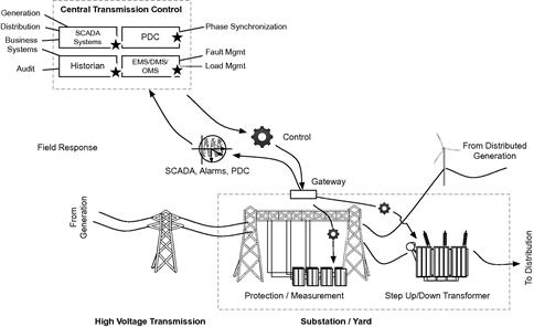
Electricity enters the transmission system after a transformer steps up the voltage to levels that are suitable for bulk transmission to the grid. This typically occurs at generation facilities, but voltages may also be stepped up or down at substations where multiple lines converge, aggregate, or intersect. Substations or “yards” are a primary component of transmission systems. Substations also provide voltage measurement, voltage regulation, and line protection so that electricity can be transmitted as safely and efficiently as possible. Transmission lines carry electricity over either multiphase alternating current (AC) or high voltage direct current (HVDC), typically at high voltages (115–345 kV), extra high voltages (500–765 kV) and ultra-high voltages (greater than 800 kV).6 The high-voltage energy is transmitted to distribution systems, including secondary and tertiary substations, where electricity is then stepped down to usable voltages and distributed to the end customer.
Modernization of transmission focuses on adding intelligence and automation to make energy transmission more efficient (through grid optimization such as dynamic load and condition management), more reliable (through attack-resistant and self-healing capabilities), and more flexible (supporting distributed generation).6
As with generation systems, modernization of the grid to accommodate smart transmission systems presents a cyber security challenge. Many components of a transmission system—substation automation, GPS/satellite timing and other wide-area measurement systems, advanced protection and control6—when combined with distributed controllers and SCADA systems result in a new attack surface that exposes transmission to a variety of new cyber threats. When assessing the transmission system for risk of cyber attack, potential targets of a cyber attack—and the potential vectors of accessing these targets—must be identified. Some targets within the transmission infrastructure include the following important systems:
• The transmission SCADA and substation automation systems.
• The phase measurement systems and phase data concentrators.
• The line protection systems used to prevent surges and outages.
• The transformers used to shape electricity to required voltages for safe and efficient transmission.
Each of these systems, and the devices that comprise these systems, will be discussed below in detail to identify specific features and capabilities of each system that could expose the system to a cyber attack.
Transmission SCADA systems and substation automation
Transmission SCADA systems, or T-SCADA, provide similar functions to transmission that generation SCADA or G-SCADA systems discussed at the beginning of this chapter provide to generation facilities, that is, they provide supervisory (monitoring) control (automation) and data acquisition (measurement). T-SCADA systems are typically designed to manage and control automated substation processes, in the same way that a G-SCADA system manages and controls automated generation processes.
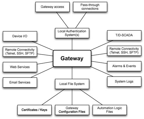
T-SCADA systems depend very heavily on a combination of capabilities: measurement (or collection of measurements from device I/O), monitoring via a user console, and control (via automation logic or direct HMI). Many substation gateways combine T-SCADA functions with network communication capabilities, and act as a central nexus of information aggregation, translation, and communication in addition to SCADA functions. These gateways provide several key functions to the transmission system:
• They provide translation between multiple device and protocol messages from substation protection systems, controllers (remote PLCs or RTUs), intelligent electronic devices (IEDs), synchrophasors, etc. and centralized substation management systems or energy management systems (EMS).
• They provide substation control and distributed T-SCADA. The gateway, which is a computing platform (a server), executes process automation logic (such as ladder logic) much like a PLC.
• The gateway provides activity logging to the substation, where faults, events, and other data (e.g. measurements) are recorded.
• They provide communication back to the control room. Communication channels typically include communication between gateway T-SCADA and centralized T-SCADA or EMS systems (for central management) as well as communication to substation devices for remote maintenance or management of individual assets.
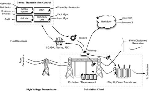
Figure 2.9 illustrates some of the systems that are accessible and/or that can be manipulated through the compromise of T-SCADA. Manipulation of transmission systems—such as phase measurement and synchronization, power conditioning, load, etc.—is obvious. Less obvious is the manipulation of G-SCADA and distribution SCADA systems, which often utilize data from T-SCADA to ensure proper loads are being generated and delivered to the distribution systems. Historians are also influenced, as falsified or manipulated data inbound from T-SCADA into a historian result in a lack of historical data integrity. Data historian systems are also being used more and more for real-time business intelligence purposes: Rather than simply archiving data for historical reference, the historian is calculating efficiency metrics, isolating trends, and otherwise adding business context to process data. Perhaps, even more significant, however, is the role that more advanced substation gateways play in transmission.
Looking at several commercially available substation gateways, a number of common features are available that raise cyber security concerns. At least one gateway (which will not be identified here) supported e-mail notifications. While ICS best practices limit SMTP to outbound messaging, and therefore prevent inbound attacks using SMTP, the use of common services such as SMTP does raise questions of risk. Can outbound messages be altered, spoofed, or otherwise manipulated? Almost all gateways offered the following:
• Time synchronization via the network time protocol (NTP) and/or IRIG-B.
• Web-based data viewing via HTTPS.
• Remote shell access via SSH (with SCP).
• Remote file transfer via FTP or SFTP.
• USB ports for data extraction.
• Multiple Ethernet interfaces.
• A terminal server (for connection to the gateway and/or to devices inside the substation).
• Support for common SCADA and automation protocols including IEC 61850, IEC 60870, DNP3 (serial and TCP), and Modbus (serial and TCP).
These features alone represent a host of open ports and services, many of which represent potential attack vectors into the substation. Interestingly, most gateway products that were assessed had security measures in place for the connectivity (e.g. SSH, SSL) and for authentication (e.g. RADIUS), but only one utilized any sort of host security for malware prevention on the gateway itself. This is a major oversight in the industry, as the gateway is perfectly positioned within the transmission architecture for use by a cyber attack: it is reachable via both the wide area network (TCP/IP) and the device network (serial bus protocols), it supports both control and data acquisition aspects of SCADA, it is responsible for messaging to and from the control room, and (typically) it runs a commercially available OS. Figure 2.9 illustrates many systems that could be influenced or manipulated with root or administrative access to a substation gateway. Essentially, by compromising the gateway, an attacker would have the ability to directly manipulate all communications to and from the substation—including the command and control capability of centralized T-SCADA or EMS (see Figure 2.10).
Possible exploitation of T-SCADA, therefore, includes compromise of the substation gateway in addition to compromise of the wide-area communication infrastructure (including VPN keys, et al.) and/or the compromise of the T-SCADA/EMS servers.
 Compromise of the wide–area communication infrastructure
Compromise of the WAN connections between substations and the control room is a serious concern. Luckily, at least some degree of secure connectivity was offered in most of the systems that were researched for this book. The use of SSL and/or TLS—which is specified for communication under the IEC 61850 standards—is used almost ubiquitously for wide-area connectivity, for example. However, vulnerabilities still exist—man-in-the-middle attacks can breach some SSL connections, while newer SSL exploits may be used to effectively denial of service (DoS) an SSL server, shutting off its ability to communicate on the network by causing a storm of SSL renegotiations7 and a successful attack against an endpoint can allow a hacker to benefit from secure transmission to operate invisibly, unless a mechanism has been deployed to inspect encrypted communications. Older versions of TLS are also susceptible to toolkit-based attacks from the Browser Exploit Against SSL/TLS (BEAST).8 In other words, defense of a substation requires a broader defensive strategy than TLS alone.
Of significant concern is the continued use of e-mail and web services in these devices. Email is used primarily for sending alarms, diagnostic messages, and other notifications to administrators. While convenient, sending an e-mail requires an open port. HTTP is mostly used to access a web interface, but again requires the use of open TCP ports. These ports and services represent a clear (and unnecessary) avenue for compromise. Attacks might include man-in-the-middle attacks, manipulation of the TCP/IP communication channels between the substation gateway and the T-SCADA server(s) in the control room, creation of “covert” communication channels between a compromised substation and other substations in the network, denial of service, or data exfiltration.
Because the T-SCADA server or substation gateway controls the movement and protection of high-voltage electricity, reliability and safety can be impacted directly if the communication to and from these devices becomes compromised. The malicious injection of SCADA protocol traffic to or from the substation, for example, could directly manipulate automated protection systems to trip lines unnecessarily, causing an outage. The reliance upon Syslog for communication of activities outside of the substation (inside the substation, messaging typically occurs via GOOSE or similar protocols) simplifies misdirection to corporate IT resources by manipulating or blocking messages. In addition, centralized cyber security detection systems that rely upon logs (e.g. log management or security information and event management systems) can be misled through the malicious injection of logs from the substation to the control room, unless caution is taken to transfer logs over secure and authenticated channels.
Privacy issues are also a concern, as important data about energy usage could be intercepted and stolen from the wide area. This is of special concern whether data from the advanced metering infrastructure are communicated back to the control room via T&D communications, versus direct secure AMI communication, as metering data often include customer usage, billing, and other personal data (see Chapter 4, “Privacy Concerns with the Smart Grid”).
Compromise of the T-SCADA or EMS server(s)
Compromise of the T-SCADA or EMS server(s) results in the same risks to reliability and safety as in the discussion of G-SCADA systems earlier in this chapter: The SCADA system provides ultimate command and control over the industrial process, and therefore, breaching the T-SCADA server provides ultimate command and control over those processes throughout the transmission system. T-SCADA, like G-SCADA, is responsible for monitoring inputs and outputs: Inputs might include phasor measurement, line voltages, frequency, transformer settings, load, faults, while outputs might include capacitance, load adjustments, (step-up/step-down controls), protection/breaker controls. By compromising the T-SCADA server(s), these inputs and outputs can be redefined:
• Values can be misrepresented to centralized SCADA console, to centralized data historians, and to other auxiliary systems that utilize T-SCADA data (e.g. other interconnected SCADA systems or back-office systems).
• New values/logic can be written to the controller(s)—for example, to substation automation logic in the gateway or to distributed IEDs or RTUs on lines or in secondary substations.
• Direct manipulation of secure communication channels to substation gateways and other substation assets (most secure communication channels between T-SCADA servers and substation gateways) utilizes SSL or TLS and utilizes certificate-based authority. By compromising an authorized device with appropriate certificates, the secure wide-area communications are also compromised.
Compromise of the substation gateway
Again, the substation gateway is a prime target for attack, because it provides communications between a substation and the control room, in addition to substation automation capabilities. Gateway communication capabilities typically extend to provide a central access point (via a terminal server) to substation devices that are managed via the gateway’s I/O. Therefore, compromise of the gateway allows an attacker to manipulate many systems:
• Manipulation of substation devices, via direct injection of SCADA commands onto the device network.
• Manipulation of other substation devices, via pass-through access to device configuration/diagnostic interfaces.
• Manipulation of substation devices, via manipulation of automation logic controlling those devices.
• Manipulation of gateway authentication to enable unauthorized remote access (i.e. a backdoor) to substation devices.
• Indirect manipulation of substation automation logic, via false reporting to centralized T-SCADA systems, tricking the human operator into making unnecessary and potentially harmful changes to the automation logic.
• Remote manipulation of substation automation logic via remote access of the gateway’s “local” HMI (i.e. “popping the HMI”).
Phasor measurement units/synchrophasers/phasor data concentrator
Electricity flows from higher voltages to lower voltages and from higher phase angles to lower phase angles. Therefore, to effectively transmit electricity throughout the transmission system, it is necessary to understand the voltage and phase angle at key locations in the grid. A phasor measurement unit (PMU) is a device that measures these electrical characteristics on the grid and then communicates them back to a phasor data concentrator (PDC) and ultimately to T-SCADA systems.
PMUs are often called synchrophasors because modern PMUs synchronize multiple phasor measurements from different points on the grid to a common time source (typically using IRIG-B, a GPS-based time synchronization protocol). A synchronized PMU or synchrophasor is able to accurately measure the quality of the grid, both in terms of voltage and in terms of current, at any given time across all measurement points. Understanding distributed phasor measurements allows the grid to be utilized more efficiently, by adjusting load throughout the grid to the maximum dynamic limits of the transmission system, at any given point. The result is more efficient, reliable and safe transmission, because available transmission lines are able to transmit the maximum amount of power, while surges or ebbs in load can be reduced or eliminated.
Synchrophasors consist of measurement, synchronization, and logging functions. Typical PMUs will provide multiple measurements up to 30 times per second, as specified by the IEEE Synchrophasor Standard, C37.118–200510 (see “Standards and Protocols,” below). However, an assessment of several commercially available synchrophasors as many as 64 samples per cycle may be supported. These readings are time-stamped to the synchronized time source and collected by the PDC, which samples the data logging mechanisms of the PMU in real time. The centralized and synchronized measurements are then utilized by T-SCADA and energy management systems to adjust transmission rates, manage outages, and other functions.
Many automation devices include phasor measurement capabilities, just as many synchrophasors support remote management and control, enabling transmission quality to be automated. Unfortunately, this also exposes transmission quality to the same vulnerabilities and exploitations of other SCADA system components.
As with substation gateways, most commercially available synchrophasors researched for this book provided a variety of features that in turn equate to open ports and services—in other words, to direct attack vectors:
• Networking interfaces, including Ethernet for routable connectivity and RS485, RS232, RS422, G.703, and others device I/O.
• Multiple protocols, including IEC 61850, DNP 3.0 (serial and TCP), Modbus (serial and TCP), IEC 60870-5-104, and the Ethernet Global Data (EGD) protocol.
• Remote communication between PMUs and PDCs via IEEE C37.118 Standard for synchrophasors for power systems.
• Console or management access to phasor data at the PDC, often over open protocols such as HTTPS.
Synchrophasors, like most industrial automation systems, utilize commercial operating systems (typically Windows, especially on larger PMUs and PDCs). Combined with a variety of interfaces, ports, and services, a synchrophasor that is misconfigured by the vendor or the end user could represent a degree of vulnerability to the device itself.
Compromise of the phasor measurement infrastructure
If a synchrophasor is compromised, the damage that results could be as subtle as a loss of transmission efficiency up to the disruption of service. For example:
• Disabling a PMU or PDC could stall line condition monitoring and any automation process that depends upon it.
• EMI jamming of satellite synchronization could cause erroneous load condition reports due to improper timing.
• Manipulating a PMU or its phasor measurements could cause erroneous load condition reports that could lead to improper load management.
• Manipulating phasor measurements could result in erroneous fault indicators, resulting in unnecessary recovery actions.
• Manipulating process logic on a PMU or PDC could result in improper operations as the result of accurate phasor measurements.
• Manipulation of phasor measurements could interfere with line protection, enabling power swing, out of step conditions, or other unwanted line conditions.11
Line protection and monitoring systems
Line protection systems combine metering and measurement with protection mechanisms to prevent undercurrent and overcurrent conditions. Typically, line protection consists of breakers that will trip to prevent a potentially hazardous fault—much like a home circuit breaker will trip in response to a power surge, in order to prevent a fire or other hazard. More sophisticated protection systems combine line monitoring with automation logic to allow appropriate and efficient responses to a variety of line conditions, overcurrent protection, power swing protection, and recovery, including under-frequency load correction, breaker fault detection and isolation, and synchronization loss detection and recovery.11
Line protection systems obviously rely heavily upon line monitoring, including current, voltage, frequency, power, energy, and phasor measurement. The measurement functions of a protection system overlap with phasor measurement units, and therefore, many protection systems include PMU capabilities (according to IEEE C37.118) or integrate with external PMUs.
Line monitoring is also important for the detection of various abnormal conditions that might indicate equipment failure (or imminent equipment failure). Proactive maintenance of substation devices such as transformers and breakers can extend their life, and therefore, condition monitoring can directly influence the ROI of substation equipment. Proactive maintenance also enables failing equipment to be safely repaired or replaced prior to an incident or outage.12
Protection and monitoring devices once again rely heavily upon common standards and are often built atop commercial operating systems. Researching several protection systems, there is once again a common set of features including:
• Ethernet interfaces, serial interfaces, and USB interfaces.
• Protocol support including TCP/IP, IEC 61850, IEC 60870, Modbus (serial and TCP), DNP3 (serial and TCP), EGD, and IEEE C37.118.
• Support for TFTP, HTTPS, SMTP, and other common network services (SNMP, NTP, PTP, etc.).
• Support for local automation logic, used to control outputs (e.g. breakers) in response to inputs (line measurements).
• Local and remote consoles or displays for management and control of protection services.
• Event and alarming mechanisms to log measurements and activities and provide alerts in response to faults or other conditions.
Transformers
A transformer is a device that transfers electricity from one coil to another via inductive coupling, either stepping up or stepping down the current by varying the delta between the coils. Step-up-transformers are necessary for electric transmission, as they are able to increase voltages to levels where power can be transmitted efficiently over long distances. Step-down-transformers reduce voltages, ultimately to 110 V/220 V for consumption by the end user. Step-up transformers are therefore located at the ingress to the transmission system (from generation), while step down transformers are located at the egress of the transmission system (to distribution). “Step-up/step-down transformers” are transformers capable of either stepping up or stepping down voltages, and are useful in substation applications where voltage regulation must be controlled to support the optimized, self-healing, and reliable nature of a smart transmission system.
Transformers typically communicate to protection systems and/or substation automation systems over IEC 61850. There may be a direct communication to a centralized T-SCADA system, or an indirect communication to centralized T-SCADA via substation automation systems in PMUs, gateways, and protection systems.
Examining several commercially available transformers, these devices provide a much smaller attack surface than other components of the transmission system:
• Network communications are typically limited to IEC 61850 (ideally, protected according to IEC 62351).
• There are no inherent SCADA or controller functions; the transformers rely on external control from protection systems and T-SCADA systems.
• There are no Web-based consoles or interfaces, or other remote consoles using common protocols.
This does not exclude transformers as targets for cyber attacks, but it does limit their usefulness as an initial attack vector. The important role that transformers play in the transmission and distribution systems makes them a likely target to an attacker that gains a foothold in other systems, such as substation automation, protection, condition monitoring systems, and other systems that interact with the transformer. One reason for concern is that manipulation of a transformer could cause significant short-term or long-term damage. For example, by transforming electricity to non-optimal voltages while reporting expected measurements back to monitoring systems, equipment deterioration could be accelerated and imminent failures might go unnoticed. Likewise, voltages could be increased to levels that are unsafe due to downstream line conditions.
Distribution architecture
The “distribution” architecture begins at the termination of the transmission system, and ends at the meter—the demarcation where a home or business consumes the distributed electricity. Again, transformers are used to shape electricity, typically stepping down voltages for distribution at lower voltages and ultimately stepping voltages down to levels usable by the metering infrastructure and the end consumer. Distribution lines are numerous and typically support many end users: from city blocks, to suburbs, to neighborhoods, to counties, etc.
Like transmission systems, distribution systems also utilize substations for energy conditioning, monitoring, protection, and automation. Also like transmission systems, distribution systems communicate back to a centralized SCADA master terminal unit (MTU), distribution management systems (DMS), outage management systems (OMS), and a variety of back-office systems located in a data center or central control facility. Like transmission systems, they also rely heavily upon line measurement and protection systems to effectively manage energy usage, monitor and respond to outages, etc.
In fact, distribution systems operate similarly to transmission substations in many, though they tend to be smaller, more numerous, and operate at lower voltages than the primary and secondary substations used in the transmission system. The specific functions of a distribution system also differ slightly: where transmission systems focus more on generation control, delivery, condition management, energy storage/reserve management, interchange management; distribution focuses more on load management and modeling, two-way power flow, risk analysis and outage management, and dynamic feeder reconfiguration (DFR), islanding and other isolate, bypass or otherwise avoid outages.6
The distribution architecture is shown in Figure 2.11, and consists of several important systems:
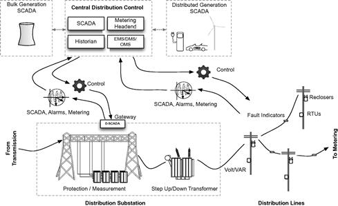
Each of these systems will be discussed below in detail to identify specific features and capabilities of each system that could expose the system to a cyber attack.
Distribution SCADA/DMS
Distribution SCADA or D-SCADA systems are responsible for the control of distribution operations, including manual and automated control of load management and DFR.6 Distribution substation automation, like transmission substation automation, is typically controlled via D-SCADA systems within the substation, often in a gateway device, while also communicating back to a larger D-SCADA system in a central control center. Remote D-SCADA servers will typically offer similar features and capabilities as those used in transmission—they are communication gateways that provide: the network communications capability to substation devices (LAN, serial) and to centralized systems (WAN); data concentration functions to collect and aggregate substation data from other systems; automation capability through programmable logic (i.e. a controller); metering functions; fault recording and alerting; and transformer monitoring and control.
Just as in transmission substations, D-SCADA systems are often feature rich and designed to accommodate many remote communication and control functions. It is therefore very typically for a distribution gateway to support:
• Time synchronization via NTP or IRIG-B.
• Management interfaces via HTTP, SSH, or terminal access.
• Terminal server capabilities for remote connectivity to other substation devices.
• File transfer via FTP or SFTP for configuration, data acquisition, and upgrades.
• Keyboard, video, mouse, and USB ports.
Again, the robust nature of D-SCADA provides a broad attack surface: The many available interfaces, ports, and services combined with the use of commercial operating systems and both LAN and WAN connectivity make these systems a likely inbound attack vector, as well as prime targets for attacks. This enables both direct attacks (to impact substation automation) and staged attacks (using the gateway as a launching point for attacks against protection, conditioning, monitoring, and other systems), by exploiting weaknesses and vulnerabilities in D-SCADA.
Compromise of distribution SCADA
The problem of interconnectivity continues to present a cyber security challenge throughout the distribution system. With automation and intelligence come vulnerabilities and attack vectors, and the interdependence of these systems on each other provides a playground for cyber attackers. Figure 2.12 highlights some of the systems that can be reached and compromised in automated distribution systems.
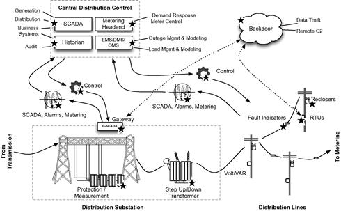
The interdependence of disparate systems requires that communications be established. That established communication path then becomes a vector for threat propagation. Once D-SCADA is compromised, it is therefore possible to access and breach outage management systems, the AMI headend, or even G-SCADA systems back at the beginning of the process in the power generation facility! As more systems become interconnected, this risk increases unless digital access controls are established between all interconnections. At the same time, as more systems become interconnected, it becomes cost prohibitive (and often logistically challenging) to implement security controls to enforce each and every interconnection.
Field controllers and automated field devices
A field controller is a remote terminal unit (RTU), IED or other distributed controller used throughout the distribution system, outside of the substation. Automated field devices include auto-reclosers, breakers, volt/VAR (voltage and VAR, or volt–ampere reactive) regulators, and capacitors.6
Examining commercially available RTUs, there is once again a proliferation of interfaces, protocols, ports, and services that give substation gateways such a broad attack surface:
• Ethernet and serial interfaces. Often with multiple Ethernet LAN interfaces and optional wireless capabilities including WiMax, radio, CDMA, GSM, and satellite.
• Support for IEC 61850, DNP3 (serial and TCP), and Modbus (serial and TCP).
• Support for automation either as a node in a centralized automation systems (connecting back to a centralized D-SCADA system) or as a distributed automation system using built-in controller logic.
• USB interfaces and/or removable flash-card interfaces for data extraction and firmware upgrades.
Examining commercially available volt/VAR systems, reclosers, feeders, and other field devices, there are far fewer communication vectors:
• Limited network interfaces—often limited to two-wire serial interfaces.
• Support for IEC 61850, DNP3 (mostly serial), and/or Modbus (mostly serial).
• Limited support for automation. Some auto-reclosers included local control capability, as did some capacitor controllers and some distribution feeder controllers. However, the majority of field devices examined connected only to the field RTU or IED.
Luckily, field devices tend to rely almost exclusively on 61850 or serial Modbus or DNP3 communications for automation, utilizing the upstream controller for all operator interaction. As a result, unnecessary network services such as HTTP, SMTP, SSH, FTP are rarely found in field devices.
Compromise of distribution field devices
The compromise of field controllers and/or field devices in the distribution network could result in almost any type of consequences ranging from inefficiencies in operations, to inaccuracies in reported data and to outages. For example, auto-reclosers are designed to protect against power surges and to recover once conditions are normal. Manipulation of line conditions could cause a recloser to trip unnecessarily. The result would cascade throughout the distribution system. A truck might be dispatched to repair a fault that doesn’t exist, for example. At the same time, a recloser might be compromised and taken offline while open, locking remote control and requiring a truck roll to restore power where there otherwise wouldn’t have been an outage.
Complete compromise of an RTU could allow a cyber attacker to insert malicious logic into the controller. Consider a scenario where a cyber hacker breaches the power distribution of a neighborhood with certain demographics. Malware within a field RTU could cause random, intermittent failures, while normal conditions are reported back to DMS and central D-SCADA systems—effectively disrupting power distribution to a target area. This could be a nuisance attack or something more consequential. If politically motivated, the attack might be used to disrupt power to voting facilities in opposing political territories. Stronger motives could attempt to coordinate power outages in police or emergency response centers during a terrorist incident
False indications of outages could instigate a storm-level response scenario, again for relatively benign reasons or highly sinister intent. The potential for disruption gets worse when you consider the many tangential systems that are reachable via the distribution network, specifically advanced metering.
Metering and AMI
While advanced metering will be discussed in detail later in this chapter (see “Metering Infrastructure”), it’s important to note that advanced metering headends are often located in distribution substations. This is because advanced metering, demand-response systems, and distribution are closely interdependent systems. A successful cyber attack on a distribution device could therefore be the first step in a staged attack against the AMI.
Advanced metering architecture
In legacy power systems, analog meters measured usage at the demarcation of the home or business. The meter lacked any advanced communication capability, requiring a human to visit and read each and every meter (many modern meters provide contact-free collection of information, but a human still must be in close proximity). While analog meters could be “hacked” by manipulating the magnetic resistance that controlled the analog meter dials, the result of such an attack was isolated to the source (and also fairly easy to detect). Smart Grids add considerable sophistication to metering, and as such they utilize new “smart meters” that not only measure energy utilization, but can also be used to remotely connect or disconnect meters. Smart meters are able to receive commands and communicate utilization to and from a centralized system, eliminating the need for a human meter reader.
This is accomplished by the advanced metering infrastructure (AMI). AMI systems are utilized by many energy, water, and gas utilities. AMI architecture consists of three primary components: smart meters, a communication network, and an AMI server or headend.13
The smart meter is a digital meter consisting of a few key elements:
• A solid-state meter for real-time data collection
• A microprocessor and local memory to store and transmit digital meter measurements.
• A communication network often including a home network connection for home automation and other advanced in-home services.
As with any device, the presence of a microprocessor and memory equates to some degree of risk. Depending upon the complexity of the code and the maturity of the smart meter vendor’s secure coding practices, it may be possible to compromise the meter directly.
Smart metering also requires interconnectivity of smart meters, which may be deployed by the millions. As such, a highly scalable communication network is required. A variety of network technologies are used in AMI systems, including broadband over power line (BPL), power line communications (PLC), radio networks, or telecommunications (landline, cellular, paging, etc.) networks.13
Smart meters communicate, ultimately, to the AMI headend. A headend will typically consist of an AMI server, which is primarily responsible for collection of meter data, and a meter data management system (MDMS), which manages that data and shares it with demand response systems, historians, billing systems, and other systems.13
Smart meters are also closely connected to in-home systems such as home energy management systems (HEMS), interfacing with both HEMS and in home devices (IHDs) via a home area network (HAN)—primarily as a means of home power efficiencies. This can include enabling the home power consumer to purchase energy when the pricing is low and store it as a reserve against periods where rates are higher, rather than relying solely on time-of-use management and improved in-home energy monitoring.14 In-home systems vary widely in the design, devices, and technologies, and therefore fall outside the scope of this book. However, they are discussed briefly below under “In-home Systems,” because they are an interconnected system and should be considered both an attack surface and a potential vector of attack to AMI and distribution systems.
An assessment of commercially available smart meters found several common features and capabilities, mostly around network connectivity and manageability. Network interfaces, including IEC 61107 optical ports, RS232, RS485 serial ports, modems (typically GSRM or CDMA), ZigBee, and others. Diagnostic ports are often infrared or short-range wireless interfaces to enable easy connectivity to digital meter readers and diagnostics tools carried by a technician.
Remote management and configuration capability are often provided via a dedicated software system, providing meter configuration, as well as utilization and demand assessment, load profiling, disconnect capability, and other capabilities. These remote management systems are typically software based and installed on a utility-owned Windows computing platform. If installed on an unsecured server, these systems could be compromised, providing direct access to the configuration of entire smart meter fleets.
Looking at AMI headends, collection and MDMS systems are also typically software based, utilizing utility-owned Windows computing platforms. In addition, most MDMS systems utilize commercial relational database management systems (RDBMS). The use of an uncontrolled commercial operating system introduces the risk of OS vulnerabilities, especially as deployed systems age—just like with SCADA servers, gateways, controllers, and other devices throughout the Smart Grid; these systems, while relatively new at the moment, can be expected to operate over many years, and there distributed nature and real-time operation makes patching difficult. In addition, the use of commercial databases to store collected data presents the risk of a database attack. Either risk represents a vulnerability to the AMI and all underlying systems, such as demand-response and billing systems.
Compromise of the smart meter
Smart meters can be physically hacked to provide the same metering manipulation that could be had from analog meters using magnets and wire. Smart meters may be hacked by directly accessing on board memory, connecting to diagnostics ports, or via any available network interface(s). Security researcher Brian Krebs points to the use of common optical converter hardware, available for a few hundred dollars online, to access optical diagnostic ports on smart meters. Krebs also cites an FBI report that indicates this type of meter manipulation could lead to hundreds of millions of dollars of losses, as meters are altered to fraudulently under-report utilization.15
Smart meters could also be subject to DoS style attacks to prevent communication to the AMI (and therefore to billing and demand-response systems), also incurring losses to the utility. The nature of the DoS obviously varies by the AMI network being utilized: for cellular based systems, downloadable war-dialing tools could be used; both cellular and radio networks can be jammed; and more sophisticated standards such as ZigBee can be exploited using readily available tools such as the Metasploit Framework.
Compromise of AMI
Because most AMI headends utilize Windows-based applications, a variety of network-based OS and application layer attacks could compromise the headend. Why attack the headend? A successful Windows exploit on an MDMS server would provide unauthorized control over all aspects of AMI, including the representation of AMI data to other systems and the messaging and communication of AMI. Manipulation of the AMI communication network could manipulate AMI data in transit, introduce rogue or faulty data, or prevent the transmission of authorized data. This could be used to alter readings, prevent the remote disconnect of a rogue meter, or force a remote disconnect to a targeted meter—preventing electricity from being delivered to a specific target such as a hospital, airport, or other facility. Database exploits would allow direct manipulation of historical meter information or readings, but could also be used as a launching point to obtain additional access to AMI components or to propagate to other databases such as billing and customer management systems. These systems contain customer information ranging from usage profiles to billing information and represent a significant privacy concern.
In-home systems
In-home systems have not been included in the diagrams and are only briefly mentioned here. This book will not delve into the vulnerability and security of in-home devices, smart appliances, HEMS, electric vehicle charging stations, and other in-home devices (IHDs), focusing instead on the Grid infrastructure up to the home demarcation point (the smart meter). However, HEMS, IHDs, and the HANs that interconnect them do need to be acknowledged as a potential vulnerability to both the larger grid infrastructure and personal information (see Chapter 4, “Privacy concerns with the Smart Grid”). Here, we will simply acknowledge in-home systems and how they interconnect with the larger infrastructure:
• Home area networks (HANs) represent any in-home communication. Like a local area network (LAN), wide area network (WAN), or metro area network (MAN), a HAN defines the scope of the network itself rather than the devices it interconnects.
• Home energy management systems (HEMS) provide a system to monitor, manage, and automate in-home energy usage. HEMS interface with IHDs via the HAN, the AMI, and even distribution and utility back-office systems. HEMS may be located in-home as an end-user operated server, but are commonly managed Web interfaces or cloud-based systems.
• Smart appliances and in-home devices (IHDs) imbue residential appliances both large and small with intelligence, allowing HEMS to monitor and control in home power usage.
• Private generation, such as residential solar or wind generation, can be considered extremely small-scale instances of distributed generation. While they may be too small to justify large degrees of automation, they will still essentially follow the generation architectures discussed earlier in this chapter. Electric vehicle charging stations may also have the ability to sell power back to the grid and can be considered an in-bound energy source to the larger grid.
Microgrids
Microgrids are integrated energy systems that are typically used either in campuses and communities that are either remote or require sufficient load to justify local generation and distribution or in military or critical industries where a private and segmented and secured energy facility is required. Microgrids may operate in parallel with the public grid, or they may run in isolation. According to Pike’s Research, “a Microgrid is really just a small-scale version of the traditional power grid that the vast majority of electricity consumers in the developed world rely on for power service today. Yet the smaller scale of Microgrids results in far fewer line losses, a lower demand on transmission infrastructure, and the ability to rely on more localized sources of power generation.”16 At the same time, Microgrids are often deployed for specific purposes, such as military mobile electric power initiatives, which deploy Microgrids in theaters of operation to support military activities. According to the United States Army Program Executive Office for Command, Control and Communications-Tactical (PEO C3T), “A 1-megawatt, or MW, Microgrid will replace 22 of the complex’s generator sets with just four larger sets, simplifying maintenance as well as cutting fuel consumption, Bolton said. Another 180-kW, or kW, Microgrid configuration will not replace any of the remaining 74 generators, but will allow up to six of them to communicate and turn on and off in response to demand.”17 This makes Microgrids a viable solution to the issue of providing energy in the battlefield.
Even in non-mobile and civilian applications, Microgrids represent a solution to challenges of long-range transmission while increasing efficiency and reliability of energy to remote facilities. Their small scale facilitates upgrades and enhancements to the infrastructure, making it easier and more cost-effective to implement and maintain a “Smart Microgrid” than it is to deploy a full-scale public Smart Grid.
In terms of the Smart Grids in the larger sense, Microgrids represent the same technologies, systems, vulnerabilities, and cyber security challenges—although the physical location of the attacker is much more concise, these Microgrids do not have large, geographically distributed WANs as part of their architecture. In terms of Smart Grid architecture in the context of this book, Microgrids operating in parallel with the larger Grid can be considered as both independent grids—consisting of generation, transmission, distribution, and metering—as well as distributed generation facilities to the larger grid.
System interdependencies
This book, like any discussion on Smart Grid cyber security, will continuously revisit the interconnectivity and interdependency of the many systems that comprise a Smart Grid. The reason is simple: Interdependency and interconnectivity represent digital communication and data exchange, which in turn represent a vector for attack or a vector of propagation through which a successful attack can spread to other systems. The interconnectivity itself is complex—as is evident in Figure 2.13 (a reprint of NISTIR 7628 Figure 2.3). Rather than recreate these complex inter relationships here, this book will take a high degree of system-to-system communication and interdependency as a given, and will discuss specifics only as examples of attack vectors and vulnerabilities, deferring to the published reference models of NIST, the IEEE, and other groups for comprehensive mappings. However, understanding the interrelationships of the many systems within the overall Smart Grid infrastructure is necessary when planning to implement cyber security controls, and it is therefore necessary to consider these dependencies within an appropriate cyber security model (see Chapter 5, “Smart Grid Cyber Security Models”). Excerpted architectural models from NISTIR have been included in both Chapter 5 and Chapter 10, “Reference Architectures,” for convenience. In addition, both NISTIR 7628 and IEEE 2030–2011 are also listed in Appendix B, “Continued Reading.”
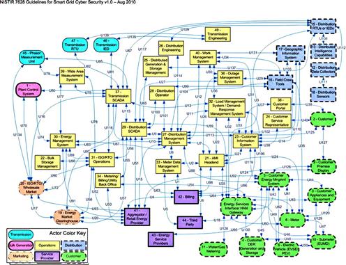
Figure 2.13 NIST Smart Grid logical reference model (Reprinted from NISTIR 7628 Figure 2.3 as public information.).18
Protocols
Most industrial protocols play a part within the Smart Grid to some degree, as the Smart Grid is a system of multiple constituent systems—many of which are industrial control systems. Most protocols—including DNP3, Modbus, OPC, ICCP (TASE.2), Profibus, Profinet, EtherNet/IP, et al.—will not be addressed in-depth within this book, however, as they are well documented elsewhere and are not exclusive to a Smart Grid (see, “Industrial Network Security: Securing Critical Infrastructure Networks for Smart Grid, SCADA and Other Industrial Control Systems” by Eric Knapp, one of the authors of this book, for more information about these protocols). While certainly not the only protocols in use within the grid, the IEEE C37.118, IEC 62351, IEC 61850, and ZigBee are of particular interest, and have special relevance to the Smart Grid.
IEEE C37.118
The Institute of Electrical and Electronics Engineers C37.118–2005 standard covers the synchronization and communication of phasor measurements, superseding the legacy IEEE 1344–1995 standard for synchronized phasor measurements. The standardization of phasor measurements is important as it allows multiple measurements to be synchronized together to obtain overall power quality assessments. Because an isolated phasor measurement has little value, the synchronization of multiple measurements, as well as the communication of multiple synchronized measurements is also defined, the real-time communications of a measurement from a PMU to a phasor data concentrator (PDC). Synchronization is accomplished by tagging each measurement with an absolute time reference, such as a GPS clock. C37.118 communication can occur over any medium, with serial and Ethernet being common implementations. The protocol requires a CRC to ensure integrity and specifies default port numbers for use over IP (4712 for TCP and 4713 for UDP) and can consist of several frame types.19 Data frames communicate the phasor measurements along with some additional information to help manage measurements in the PDC when a large numbers of PMUs are being aggregated, but there are also configuration frames, command frames, and header frames. Configuration frames describe current PMUs, while command frames can make changes to PMU.19 Header frames provide PMU details in a human-readable format and are analogous to the application banners used in fingerprinting, vulnerability assessment, and other penetration testing techniques.19 C37.118 therefore represents a similar challenge to other industrial control protocols: It lacks inherent security and provides intrinsic mechanisms to obtain data or impose control. Without sufficient compensatory protection of the PMUs and PDCs, as well as their inter communications, phasor measurements can be easily intercepted or manipulated.
Phasor measurement can represent information transfer and management challenges. The measurements themselves do occupy bandwidth, although being a lightweight protocol a single PMU is unlikely to generate excessive data rates. However, the widely distributed nature of PMUs may also necessitate low-bandwidth connectivity, and so it is a factor. More challenging will be the utilization of phasor measurements within the context of security analysis: While a PDC is designed to assess large amounts of inbound data, security information and event management tools are already burdened with potentially hundred or thousands of other data sources throughout the infrastructure and adding phasor data to that could be a challenge (see Chapter 7, “Situational Awareness”). For example, “… a phasor reporting rate of 60 phasors/for a voltage, 5 currents, 5 W measurements, 5 VAR measurements, frequency, and rate of change of frequency—all reporting as floating point values—will require a bandwidth of 64,000 bps. On the other hand, data reporting rate of 12 phasors/s for 1 voltage, 5 currents, and frequency—reported in 16 bit integer format—can be accommodated over a 4800 bps channel.”20 This will also result in 60 events per second or 12 events per second of sustained messaging to a security management tool, per PMU.
IEC 62351 and IEC 61850
IEC 62351 provides security specifications for substation communications and is broken down into several parts. 62351-3 requires transport layer security (TLS) for all TCP/IP based communications, as well as node and message authentication. 62351-4 covers manufacturing message specification (MMS) and again requires authentication and TLS. 62351-6 concerns the security of 61850 messaging, which is of particular interest.21 IEC 61850 provides data modeling, reporting, data transfer and command capability, as well as event messaging using GSE (GOOSE/GSSE) and for the storage of substation configuration data using the substation configuration language (SCL). The 61850 standard does not include security specifications of its own, deferring to IEC 62351-6. Some 61850 communications are relevant to 62351-3, requiring TLS and authentication. Some, such as GOOSE messaging, operates at layer 2 for performance reasons. Encryption is not supported because it would be impossible to maintain GOOSE’s 4ms performance requirement, so VLANs (also a layer 2 capability) are used for protection, using two reserved fields within the PDU to establish a digital signed authentication value.22 Note that this raises additional concerns, as VLANs are not a valid security control: VLAN IDs are easily spoofed, allowing an attacker to easily “hop” between VLANs, bypassing layer 3 network controls.
ZigBee
ZigBee is also a predominant standard for smart energy management, home automation and many other services, and is supported by many smart meters. ZigBee is a standards-based wireless technology managed by the ZigBee alliance and is specifically designed for low-cost, low-power wireless applications. ZigBee is designed for use across many industries and application, and as such “connects the widest variety of devices” giving “unprecedented control of the devices.”23 The ubiquitous use of ZigBee combined with readily available information about the standard and the “unprecedented control” that ZigBee provides makes it of particular interest regarding cyber security.
Summary
The Smart Grid is a very complex collection of systems that are highly intelligent and communicative. The combination of prolific measurement and monitoring produces large amounts of valuable data throughout all areas of generation, transmission, distribution, and metering. In order for this data to be used by many advanced systems—including the automation of many T&D functions, as well as advanced metering capabilities such as remote disconnect, demand-response, and billing automation—new communication networks must be established between these devices. By looking at each area of the Smart Grid, and by taking a close look at the devices that comprise each system and the networks that interconnect them, the overall vulnerability of the Smart Grid is evident. Many devices pose significant cyber security risks due to unnecessary use of ports and services, and because most systems are interconnected, the exploitation of one device could allow an attacker to migrate to other more critical systems. Individual exploitations can easily be used to launch larger, more sophisticated attacks against the Smart Grid (see Chapter 3, “Hacking the Smart Grid”).
References
1. Knapp Eric. Industrial network security: securing critical infrastructure network for Smart Grid, SCADA, and other industrial control systems. Waltham, MA: Syngress; 2011.
2. Ombello Carlo. Nuclear vs solar: clash of the numbers [document on the Internet]; August 2010. <http://www.opportunityenergy.org/?p=215> [cited July 2012].
3. Nuclear Energy Institute. US nuclear power plants [document on the Internet]; <http://www.nei.org/resourcesandstats/nuclear_statistics/usnuclearpowerplants/> [cited July 2012].
4. US CERT. Control systems security program (CSSP), industrial control systems cyber emergency response team [document on the Internet]; <http://www.us-cert.gov/control_systems/ics-cert> [cited July 2012].
5. Lagner Ralph. In 2011 ACS conference, September 21, Washington DC; 2011.
6. Sorebo Gilbert N, Echols Michael C. Smart Grid security: an end-to-end view of security in the new electrical Grid. Boca Raton, FL: CRC Press; 2011.
7. Fisher Dennis. Attack tool released to exploit SSL DoS issue. Threat post [document on the Internet]; October 2001. <http://threatpost.com/en_us/blogs/attack-tool-released-exploit-ssl-dos-issue-102411> [cited July 2012].
8. Common Vulnerabilities and Exposures. CVE-2011-3389 [document on the Internet]; <http://www.cve.mitre.org/cgi-bin/cvename.cgi?name=CVE-2011-3389> [cited July 2012].
9. United States Department of Energy. ICS-ALERT-12-046-01—Increasing threat to industrial control systems, February 2012.
10. Stenbakken Gerard., Nelson Tom. Gaithersburg, MD: National Institute of Standards and Technology; Zhou Ming., Virgilio Centeno. Virginia Polytechnic Institute and State University. Reference values for dynamic calibration of PMUs. Blacksburg, VA.
11. IEEE Power System Relaying Committee Working Group D6. Power swing and out-of-step considerations on transmission lines, IEEE; 2005.
12. McDonald John. P.E. Substation automation basics—the next generation. Electric energy online [document on the Internet]. <http://www.electricenergyonline.com/?page=show_article&mag=43&article=321> [cited July 2012].
13. EPRI. Advanced metering infrastructure (AMI). Palo Alto, California; 2007.
14. HEMS Technology. Energy efficiencies in a home energy management system (HEMS) [document from the Internet]; August 9, 2010. <http://hemstech.com/blog/?p=66> [cited october 2, 2012].
15. Brian Krebs. FBI: smart meter hacks likely to spread [document on the Internet]; April 2012. <http://krebsonsecurity.com/2012/04/fbi-smart-meter-hacks-likely-to-spread/> [cited July 2012].
16. Pike Research. Abstract of microgrids: distributed energy systems for campus, military, remote, community, and commercial & industrial power applications: market analysis and forecasts. Navigant Consulting, Inc. 1Q, 2012 [document from the Internet]. <http://www.pikeresearch.com/research/microgrids> [cited October 3 2012].
17. Schwerin Claire Heininger. Army deploys microgrids in Afghanistan for “smart” battlefield power. United States Army PEO C3T. [document from the Internet]; June 28 2011. <http://www.army.mil/article/60709/> [cited October 3 2012].
18. The Smart Grid Interoperability Panel—Cyber Security Working Group. NISTIR 7628 guidelines for Smart Grid cyber security: vol. 1, Smart Grid cyber security strategy, architecture, and high-level requirements. US Department of Commerce, National Institute of Standards and Technologies; August 2010.
19. Martin KE, Hamai D, Adamiak MG, et al. Exploring the IEEE standard C37.118–2005. IEEE Trans Power Deliv. 2008;23.
20. Adamiak Mark, Premerlani William, Kasztenny Bogdan. Synchrophasors: definition, measurement, and application [document on the Internet]. <http://www.gedigitalenergy.com/multilin/products/synchrophasors/synchrophasors.pdf> [cited October 5 2012].
21. IEC Technical Specification 62351–1. Power systems management and associated information exchange—data and communications security Part 1: communication network and system security—Introduction to security issues. Geneva, Switzerland: International Electrotechnical Commission (IEC); 2007.
22. IEC Technical Specification 62351–6. Power systems management and associated information exchange—data and communications security Part 6: Security for IEC 61850. Geneva, Switzerland: International Electrotechnical Commission (IEC); 2007.
23. The ZigBee Alliance. About ZigBee [document from the Internet]. <http://www.zigbee.org> [cited July 2012].