Security Models for SCADA, ICS, and Smart Grid
Information in this chapter:
• NISTIR 7628 Smart Grid cyber security architecture
• EU M/490 and the SGCG reference architecture for the Smart Grid
• IEEE 2030-2011 Smart Grid power system, communication technology, and information technology reference diagrams
• ISA-62443: zones and conduits and Smart Grids
Many cyber security models exist, including several—such as those presented within NIST and ISA guidance documents—that are highly relevant to critical infrastructure. But what about the Smart Grid? The Smart Grid is a meta-system that is built via the interconnection of many smaller systems. Some are business systems; some are industrial control systems. Some are built for SCADA and automation, some for measurement, some for control, and some for safety. Some are industrial in nature, while others are commercial or consumer oriented.
All of the publically available reference models are valuable, and it is highly recommended that these standards be studied in detail by anyone attempting to fully understand the intricacies and complexities of Smart Grid system interoperability (see Appendix B, “Recommended Reading”). NISTIR 7628 is the poster child for the sophistication of the Smart Grid, while the IEEE 2030 simplifies things by looking at power, information and communications systems separately. The Smart Grids Coordination Group’s reference architecture, built in accordance with European Mandate M/490, offers a simplified model while extending the architecture to differentiate between distributed generation and bulk generation.
Understanding interoperability is important because it’s the necessary first step to determining boundaries and implementing security controls. The concept of “zones and conduits” (best known from ISA-62443), is much easier to implement in simpler, more isolated systems. However, though highly applicable to the Smart Grid, defining zones and conduits within a complex meta-system like the Smart Grid is hardly trivial. The “enclave” model, documented in “Industrial Network Security,” takes a different approach: rather than grouping assets based on security concepts (as is the case in ISA 62443), this model groups assets based on functional concepts—specifically the asset’s functional role within one or more digital systems. This approach is similarly appropriate yet also difficult to deploy in a highly interconnected system such as the Smart Grid. The “enclave” model requires defining functional groups and securing them internally as well as securing the connections between groups:
“Functional groups need to be defined. While simple in concept, this can be a difficult and time consuming process. It begins by logically grouping networks, assets, the operations that they perform, and even the users who are responsible for those operations. These overlapping groups are then examined to identify the common denominators between systems. The result is an enclave: exclusive collections of only those systems that are necessary to perform a specific function.
Once defined, the enclave then needs to be secured. Ideally, every enclave would be secured to the highest degree possible. Realistically, costs and other factors make this goal unattainable. Therefore it is also necessary to identify those enclaves that represent the highest risk to safety and reliability, so that the strongest perimeter defenses can be implemented where they are needed the most (understanding the criticality of an enclave may be required for regulatory compliance purposes as well). Perimeter defenses may consist of firewalls, network IDS and IPS devices (NIDS and NIPS), router access control lists (ACLs), application monitors and/or similar security products—all of which can and should be configured to isolate the defined members of an enclave.”1
One reason that multiple security standards are referenced here is that no “one size fits all,” especially as we consider the unique security and privacy requirements of the Smart Grid at a global level. The model itself is less important than the fundamental concepts upon which they are built. Whether you subscribe to the philosophy of security-based or function-based separation, it is imperative that appropriate separation of Smart Grid systems occurs. Once groups are defined, by whatever means, the careful control over how data are communicated and utilized between systems is the most important consideration pertaining to Smart Grid cyber security—whether it is called a “conduit” or an “information path” or a “network connection” or a “flow,” etc. is largely irrelevant so long as that digital intersection of Smart Grid systems is properly controlled, managed and protected.
But how can a highly interconnected system such as the Smart Grid be realistically separated into zones or enclaves? The more interconnected a system becomes, the more difficult it becomes to logically group assets, the more difficult it becomes to enforce the separation of those groups of assets, and the more difficult it becomes to secure the communications between groups. At the same time, it also becomes more important to do so.
The first step to applying this or any model to a Smart Grid is to identify the assets, prioritize the assets, and understand how they are used, and how they should interconnect (if at all). This includes understanding concepts of trust, criticality, and dependencies as they relate to assets and groups of assets (systems). Only once this level of understanding is obtained can you effectively segment the Smart Grid into its component enclaves, zones, domains, groups, levels, etc.
However, there still the question of how each domain or zone works, and what the specific security challenges of that zone might be. By applying the concepts defined within the “three by three” cyber security model for critical infrastructure—a model developed by security company McAfee, Inc. to tailor security technology to the specific qualities of critical infrastructure networks—a more practical understanding of how to apply security can be obtained. The endpoints, networks, and applications used within each zone represent their own vulnerabilities, and therefore three levels of security must be implemented to protect each. The up-front security planning required can be challenging, but the added effort allows the correct security measures to be implemented in each area, and it becomes possible to identify where and how specific security products and technologies should be implemented within a Smart Grid (see Chapter 6, “Securing the Smart Grid”).
NISTIR 7628 Smart Grid cyber security architecture
NISTIR 7628 addresses the same risks discussed throughout this book. From NISTIR 7628, “With the implementation of the Smart Grid has come an increase in the importance of the information technology (IT) and telecommunications infrastructures in ensuring the reliability and security of the electric sector. Therefore, the security of systems and information in the IT and telecommunications infrastructures must be addressed by an evolving electric sector. Additional risks to the grid include the following:
• The increased complexity of the grid could introduce vulnerabilities and increase exposure to potential attackers and unintentional errors;
• Interconnected networks can introduce common vulnerabilities;
• The increased vulnerabilities to communication disruptions and the introduction of malicious software/firmware or compromised hardware could result in denial of-service (DoS) or other malicious attacks;
• Increased number of entry points and paths are available for potential adversaries to exploit;
• Interconnected systems can increase the amount of private information exposed and increase the risk when data are aggregated;
• Increased use of new technologies can introduce new vulnerabilities; and
• Expansion of the amount of data that will be collected that can lead to the potential for compromise of data confidentiality, including the breach of customer privacy.”2
This is a departure from the more myopic view of many energy-sector cyber security discussions, recommendations, and standards, which tend to focus on energy generation rather than the entire grid and focus on reliability of generation facilities rather than the security of the broader infrastructure that constitutes the “grid” and its supporting systems. “In its broadest sense, cyber security for the power industry covers all issues involving automation and communications that affect the operation of electric power systems and the functioning of the utilities that manage them and the business processes that support the customer base.”2
Figure 5.1 (reprinted from NISTIR 7628 Figure 2-2) illustrates the initial complexities introduced by the disparate stakeholders, influencers and customers of the Smart Grid (i.e. “actors”). With each actor (meaning a group with similar objectives and application dependencies) comes additional concerns of security awareness, policy, and governance that supersede physical and technical cyber security controls.
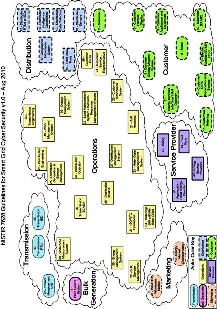
Figure 5.1 NIST’s composite high-level view of the actors within each of the Smart Grid domains (reprinted from NISTIR 7628 Part 1 Figure 2-2 as public information)2.
To further complicate matters, these actors (and the systems they influence) do not operate in isolation: Figure 5.2 (reprinted from NISTIR 7628 Figure 2-3) further illustrates the complexity of the Smart Grid by mapping the interconnections between systems.
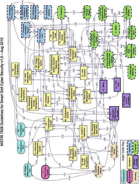
Figure 5.2 NIST’s Smart Grid logical reference model (reprinted from NISTIR 7628 Figure 2-3 as public information.)2. Also printed in Chapter 2, “Smart Grid Architecture,” and reprinted in Appendix B, “Reference Diagrams” for convenience.
The NIST IR 7628 guidance is comprehensive, consisting of three volumes—all of which are meticulously researched and articulated—outlining the requirements and inter-relationships between bulk generation, transmission, distribution, customer, service provider, operations, and marketing actors. In addition, NIST has published the Special Publication 1108R2, the “Framework and Roadmap for Smart Grid Interoperability Standards,” which is a revision 2.0 as of this writing. NIST SP 1108 does not provide the same level of detail around architectural interconnectivity, but otherwise aligns with NISTIR 7628’s model.
EU M/490 and the SGCG reference architecture for the Smart Grid
Standardization Mandate M/490 is a mandate of the European Standardisation Organisations (ESOs) to support European Smart Grid deployment and requires (among other things) the provision of “a technical reference architecture, which will represent the functional information data, flows between the main domains and integrate several systems and subsystems architectures.”3 Based on this mandate, the European Committee for Standardization’s Reference Architecture Working Group of the Smart Grid Coordination Group (SGCG) developed the Smart Grids architecture model (SGAM) framework. The SGAM is a five-layer architectural model (Business, Function, Information, Communication, and Component layers) that “allow[s] for a representation of interoperability viewpoints in a technology neutral manner, both for current implementation of the electrical grid as well as future implementations of the Smart Grid.”4 The EU model builds upon the NISTIR 7628 model in a few key ways:
1. It extends 7628 to include a new domain for “distributed energy resources” (DER) to more comprehensively define Smart Grid architectural zones (“actors” in NIST terminology), as illustrated in Figure 5.3.
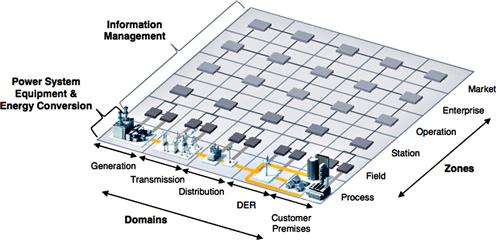
Figure 5.3 SGAM domains and zones (reprinted with permission from Figure 5.6 of the SGCG report on reference architecture for the Smart Grid).
2. It applies the five layers to the defined zones to establish a three-dimensional representation of interoperability, as illustrated in Figure 5.4.
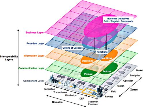
Figure 5.4 The SGAM framework with interoperability layers (reprinted with permission from Figure 5.7 of the SGCG report on reference architecture for the Smart Grid).
3. It incorporates the GridWise Architecture Council (GWAC) interoperability categories, which defines and separates interoperability requirements into organizational, informational, and technical categories.
As can be seen in Figure 5.3, the architecture itself maps out the different zones in a five by six grid, showing the interconnectivity between zones in a much more straightforward manner than NISTIR 7628. This is also a logical extension of the “3 × 3” model discussed below under “Mapping Security Requirements to Smart Grid Environments” and illustrates in Figure 5.7, and it clearly separates zones that are dependent upon field devices, process automation, substation controls, operations, etc. as they pertain to the Smart Grid. The model is very articulate in its representation of the different zones stakeholders, and functions within a distributed Smart Grid system and makes it easier to understand how the different layers of interoperability apply across zones, as illustrated in Figure 5.4.

Figure 5.5 The ISA-62443 reference model for multi-plant zone separation (source: ISA-624436).
IEEE 2030-2011 Smart Grid power system, communication technology, and information technology reference diagrams
The IEEE “Guide for Smart Grid Interoperability of Energy Technology and Information Technology Operation with the Electric Power System (EPS), End-use Applications, and Loads” again models the Smart Grid, the various actors and influencers, and the interconnection between systems. One major difference between IEEE 2030 and other standards is its intent: “The IEEE 2030 Smart Grid interoperability reference model (SGIRM) is a reference tool to provide stakeholders with a common understanding of interoperability criteria from the power system, communications, and information technology perspectives.”5—that is, its primary concern is one of interoperability rather than security per se. However, the IEEE again recognizes the diversity and interconnectedness of the Smart Grid, calling it a “System of Systems” and mapping out the connections between power systems, information technology systems, and communication systems. IEEE 2030 uses similar actors (referred to as “domains”) as NISTIR 7628: bulk generation, transmission, distribution, customer, service provider, control and operations, and markets. Primary mappings of specific domain entities however are limited to three main categories (power systems, information technology and communication technology), versus 7628, which maps entities separately for electric storage, electric transportation, distribution grid management, advanced metering, and other subsystems of the Grid. This makes the IEEE mappings slightly less comprehensive than NISTIR’s, mostly due to the perspective on interoperability of systems.
ISA-62443 (also known as ISA-SP99): zones and conduits and Smart Grids
The International Society of Automation (ISA) Standards and Practices (SP) committee 99 originally developed a road map for the creation of a series of standards, guidelines, and technical reports focused entirely on security for industrial automation and control systems more commonly known as SCADA or DCS. Prior to the final ratification of the majority of the documents within the series, the designation was officially changed to ISA-62443. The idea behind this renumbering was to aid in the eventual adoption of the standard by the International Electrotechnical Commission (IEC) making it a globally recognized standard.
Because the Smart Grid uses industrial automation extensively throughout generation, transmission and distribution, ISA SP99 security recommendations are highly relevant. ISA-62443 is based upon the physical and logical location and separation of the systems being protected, which again is highly relevant. The standard applies the important “zone and conduit” model to a provided reference architecture to identify which systems by necessity or function work as a group (zones) and how they should be separated from other groups or zones (conduits).6Figures 5.5 and 5.6 show the ISA-62443 reference architecture in a multi-plant environment, where it can be clearly seen how this model isolates functional groups and provides a single, controllable connection path between them.
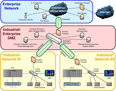
Figure 5.6 An ISA-62443 representation of zones and conduits (source: ISA-6244361).
What Figure 5.5 does not show is that it may be necessary to further subdivide a zone into multiple “subzones” which allow further segmentation of assets based on common criteria. To accomplish this, ISA-62443 considers that the first allocation of zones could be based on the physical grouping of assets (for example, a remote substation). Next, additional subzones are created that provide for a logical grouping of assets in order to apply a specific set of security requirements to these assets based on the desired level of protection.
A good example of this is to consider that the same types of security controls cannot be applied to embedded devices (PLCs, RTUs, IEDs) that would be applied to Windows-based devices (servers, HMIs). Therefore, this leads to natural subzones that provide the capability to implement primary and compensating security measures based on the subzone’s characteristics (which are shared amongst all the members in the subzone). In the case of the Windows-based asset subzone, application control technology may be used to mitigate the risk of malware, while the embedded device subzone may focus more on deep packet inspection technology to limit functional access (and in turn malicious commands) from reaching these assets. ISA-62443 also focuses on the importance of assets to the reliable operation of the system, separating assets by level of criticality. This is a common requirement among many critical infrastructure security standards and guidance, as it prevents attackers from breaching less important (and presumably less secured) systems and then pivoting from those systems to more important targets.
The challenge, again, is the diversity and interconnectedness of the Smart Grid. In many Smart Grid deployments, functionality that should exist across several dedicated assets may be combined—measurement systems, controllers, gateways, RTUS, etc. being integrated into a single physical asset. In some cases, if these functions were broken out into dedicated assets, they might be placed into separate zones with different security levels. For example, a substation gateway provides remote connectivity, interconnects business, substation and field services, provides automation control, protocol translation, and measurements. These types of multi-function device are common due to the various economic benefits of device convergence, but they present a challenge to the zone/conduit model. To accommodate this, these highly integrated devices must be very carefully deployed and managed to ensure that the proper degree of separation is accomplished.
In other words, where possible separate Smart Grid systems into zones and carefully control the connections or conduits between them. Many systems within a Smart Grid are separated physically (such as the devices and systems within a substation yard), while some are separated logically (such as a T-SCADA system which connects to many substations and most likely resides in a centralized physical data center), so the reference model shown in Figure 5.5 may be overly simplified. Knowing that pure separation may not be obtainable, introduce as many additional security measures as possible, consisting of both policies (administrative measures) and products (technical measures), to make sure that the devices involved are secure from malware, that the applications are being used as intended, and that data isn’t being manipulated.
Using the example of an electric transmission facility, as illustrated in Figure 5.7, we might separate T-SCADA systems from other SCADA or business systems within the data center. There might also be separation between protection systems and other devices located within a given substation yard. We can then focus on implementing security measures not just on devices within a zone, but on the conduits that connect these zones. In reality, however, the introduction of substation automation requires significantly greater segmentation if the intention is to prevent an attack from pivoting between zones. Gateway systems, as mentioned earlier, provide SCADA and automation capability, pass-through network connectivity to substation devices (via integrated remote access servers) and network connectivity to a centralized SCADA server or servers. We therefore have single physical devices that span multiple zones, requiring special consideration.
One way that ISA-62443 can be helpful here is in how it treats communications or “conduits” between zones and the assets contained within these zones. As in the example above, it is clear that gateway systems accept and direct communication flow to/from a large number of devices/systems, many which are likely located in multiple zones and/or subzones. These conduits that exist between zones actually contain communication “channels” that represent the actual data flow between these systems. In keeping with the ISA-62443 approach, these channels should share the same security level (or requirements) as the conduit that contains them. So when we look more deeply into the design of conduits into substation yards through gateway servers, it may be necessary to actual establish more than one security conduit that offers different levels or protection based on the channels they contain. At first, this may seem overly complex—why not just implement everything at the highest security level? The problem is that with increased security and complexity also come increased cost in terms of both equipment and maintenance and support costs. This does not consider the common vulnerabilities that can now be introduced due to misconfiguration or other errors in implementation. Consider a simple VPN concentrator. Most are licensed based on the number of concurrent tunnels established through the appliance. When you consider the potential quantity of endpoints within the Smart Grid, it becomes obvious that these figures could significantly impact cost. Therefore, the intent would be to identify and protect each conduit based on its relative security requirements. Some conduits may require simple site-to-site encryption and authentication, while others may require the additional security that comes with content inspection and threat management.
The answer to this challenging scenario of zone separation lies in securing the individual services provided by the gateway at the host level. In a sense this is effectively implementing security to the conduits interconnecting assets, and not just the assets themselves, by providing unique access controls, authentication and authorization for each. Ideally, the gateway itself will provide strong anti-malware controls to prevent root-level exploitation of the device. Even better, the multiple functions will also reside in unique and protected operating environments or “sandboxes,” using products such as Microsoft’s Hyper-V or VMware’s vSphere Hypervisor, such that the compromise of any one operating environment will not impact another. This is even possible within embedded systems such as controllers and field devices, using embedded Hypervisor technology, such as the Wind River Hypervisor, although this effort needs to originate from the device manufacturer and cannot be implemented by the operator.
The simplest way to segment a Smart Grid into zones or enclaves is to treat the Smart Grid as multiple systems rather than a single conglomerate system. We know that Smart Grids possess four unique architectural areas—generation, transmission, distribution and metering—so these can be easily approached individually. We also know that there are functional differentiators, such as protection systems versus automation systems, or remote access facilities versus end-user interfaces. Attempting to limit segmentation by architecture versus security requirements versus function will result in clear overlaps, which is why there are multiple security models and standards—each of which also overlap. Separating functional groups within each architecture (the “enclave” model) also poses problems. Using this model, there is a multitude of identified security enclaves, as illustrated in Table 5.1.
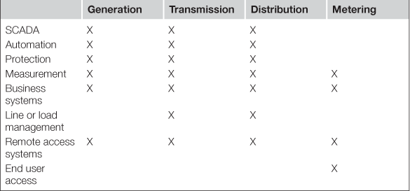
Even in this simplified table, over twenty enclaves are identified. To make cyber security realistic, a method of simplifying this approach is needed.
Mapping security requirements to Smart Grid environments
Having a reference model to work from is invaluable, and the models discussed so far all have merit. But what does this mean in terms of actually implementing security controls? Each domain or zone or actor in the Smart Grid has its own technical requirements for cyber security, its own challenges, and its own unique threats, vulnerabilities and associated risk. To help answer this question, the “3 × 3” security model was introduced in 2012 by one of this book’s authors, Eric D Knapp, in conjunction with the McAfee Critical Infrastructure business unit. This model was developed as an attempt to simplify the many diverse systems used across a variety of critical infrastructures (including but not limited to Smart Grids) so that common cyber security countermeasures could be appropriately mapped to these complex requirements, and so that gaps in existing cyber security technologies could be more easily identified. The resulting model shows three unique environments, each of which requires its own special cyber security considerations.7 They are as follows:
• Business networks, or “the Enterprise environment.”
Each of these environments was architecturally similar and often utilized the same assets and management systems across industries.7 For example, a defense manufacturer might utilize the same robotic manufacturing system as an automotive assembly line, which in turn is the same as a substation automation system or coal-burning generator. While the generalization of every critical infrastructure into common architectures is purposefully oversimplified, the generalization itself is an accurate one and helps to differentiate between the technical aspects—and therefore the security challenges—of each area.
For example, business networks are very diverse by nature. They evolve rapidly, with machines being upgraded or refreshed often, patches being applied diligently, and new applications and services being installed almost daily. There is also the need for high levels of communication and collaboration, resulting in many necessary communication paths both within and outside of the organization. Countless resources are available to discuss the Enterprise, and so little time will be devoted to it here except to make the clear statement that the Enterprise is as much a part of the critical infrastructure as the SCADA and device networks are. Because corporate IT teams and ICS operations teams are often managed separately, there is a common practice of thinking of the network infrastructure as being similarly separated, and therefore, the Enterprise is often overlooked by operations, and the SCADA and device networks are often overlooked or ignored by IT. In truth, they are highly inter-related. In the Smart Grid, the billing systems are an excellent example: they utilize real time data from the AMI and are accessed by corporate sales and finance departments. To ignore these types of interconnected business systems is to render effective Smart Grid cyber security ineffective.
In contrast to business systems, the SCADA network is very different. While there are direct commonalities—each use Ethernet and TCP/IP predominantly, and leverage Windows as the primary OS, for example—the nature of these systems is very different. The main differences come from the operational paradigms of an industrial control environment, where safety, reliability and production efficiency are paramount, and where ROI is measured against production versus cost. The result is an infrastructure that is built around stability and longevity, which in turn means that the Windows systems will differ widely from those in the business network. Instead of planning a migration to Windows 7 or Windows 8, these systems are facing vendor enforced end-of-life issues with Windows NT Server and Windows 2000 platforms. Uptime requirements also present challenges to system upgrades or replacements, and even to regular patching. As a result, the individual PCs and servers within a SCADA environment are both more vulnerable and also more difficult secure using standard off-the-shelf security products such as anti-virus or host intrusion prevention systems (HIPS). Even if these tools can be implemented successfully, the servers may have very limited CPU and memory resources, making it difficult to perform a scan against large virus definition files, resulting in less frequent (and therefore less protective) infrastructure scanning. What makes industrial control system architectures even more difficult to secure is that unlike business networks that are almost exclusively Windows-based desktops and servers (with the exception being network-attached printers and multi-function devices), industrial systems have a majority of network-connected devices running embedded operating systems with vendor-specific application software. Many traditional security controls used on business systems cannot be applied to industrial control system components.
The SCADA network is also similar to the Enterprise, using Ethernet as the predominant communication technology and TCP/IP as the predominant communication protocol. However, while Ethernet and TCP/IP are used, they are used to carry real-time industrial protocols, such as Modbus/TCP, Profinet, EtherNet/IP, DNP3 and others. This introduces two important differences between Enterprise and SCADA networks.
First, this means that the networks—though they may be designed using similar hardware and facilities—function very differently. The Ethernet network in a SCADA system will be highly sensitive to latency and jitter, due to the real-time nature of the industrial protocols—many of which rely on precise synchronization. This makes in-line network detection using traditional Intrusion Detection or Prevention Systems (IDS/IPS) difficult. The second is the network becomes an extension of the “command and control” capability of the SCADA servers, because the industrial protocols in use are designed to convey messages and response between a command and control client-server system, with (typically) little authentication or other integrity controls in place. This means that, just as with the SCADA endpoints, the SCADA network is both more vulnerable and more difficult to protect than its Enterprise counterpart.
The biggest difference, however, is in the applications. Business applications are designed around specific functions, such as maintaining a database of customer information, sharing files within or between workgroups, etc. In contrast, a SCADA application is designed to create, implement, monitor and control all industrial processes. An equal, yet separate component of the SCADA application infrastructure are the complex configuration files used to customize the application to a particular manufacturing process, and allow common equipment to be used in a wide range of industries. The configuration files contain the core of a given automation system, and include hardware configuration, operational graphics and schematics used on the HMI, custom application programs, individual controller programs (such as ladder logic or function block diagrams), and often field network device configuration databases (essential with newer “smart” devices). As with the industrial network communication protocols, these SCADA systems are essentially “command and control” applications—exactly the type of application that a hacker is (in most cases) attempting to obtain through the installation of malicious code.7 This is why the use of Meterpreter to “pop an HMI” is a common attack method; the HMI already provides the needed control; the hacker simply needs to gain access to it (see Chapter 3, “Hacking the Smart Grid”).
The third environment, the process control network—which may be referred to as the field network, the plant network, the device network, the industrial control network, or the process network depending upon the specific industry that you are dealing with—is made up of the devices that run in automation: PLCs, RTUs, IEDs, and other single-purpose devices. Again, these systems are interconnected using real-time, industrial protocols that convey commands between master or control devices (such as an HMI) and slave devices (such as a PLC, RTU, or IED). They are also responsible for transporting information and measurements from the automated system to HMI consoles, the SCADA servers, and data historians. The assets themselves are typically embedded devices running an embedded operating system. This presents an even greater challenge—not only are these systems vulnerable to attack, but also they are extremely difficult to defend. Host security of these devices is often entirely dependent upon the device manufacturer, as there is (typically) no mechanism for an end user to install security software onto an embedded device.
The networks in this environment consist entirely of industrial control protocols—and present the same challenges as in the SCADA network environment—but despite the common use of Ethernet, the physical network layer within the process control network varies widely from the copper and fiber optic Ethernet networks that are ubiquitous in the Enterprise (10/100/1000baseTx and 10/100/1000BaseFx). Cellular, satellite, radio (VHF/UHF), microwave, and other specialized networks are often in use to interconnect broadly distributed systems—making it extremely difficult to utilize commercial off-the-shelf (COTS) cyber security products in these environments. Finally, the application or data tier of this environment consists of programmable logic—the automation processes that are defined by the SCADA systems and then used by the embedded infrastructure to carry out the intended automated process.
Today, the security of this third environment is an exercise in compromise. While endpoint, network and data security controls exist, it is very difficult to implement them everywhere. The specialized and heterogeneous nature of these environments demands specialized tools. Where host security products and technologies exist, the challenge is further exacerbated by the embedded nature of these devices, which require the support of the device manufacturers. In most cases host security controls in this environment will need to be implemented by the vendor.
Of course, where an embedded process control device cannot be secured directly, it remains possible to secure the access to these devices via compensating controls. Typically this would be done using a network-based security device capable of understanding and protecting industrial control systems and protocols, such as specialized industrial control system firewalls or intrusion prevention systems. At the time of publishing, there was a new class of security appliances emerging on the market that not only offer standard Layer 3 encryption capability of IP packets using IPsec Encapsulating Security Protocol (ESP), but also provide the ability to encrypt the data payload only portion of a Layer 4 segment on IP and MPLS networks. This effectively allows network services such as class of servive (CoS) and other important L4 header information to remain in clear text and be maintained through the service provider network while the payload itself is encrypted. Put another way, ICS specific application layer protocols (transported over IP) can now have their payloads (or data) encrypted and sent across public networks, insuring data protection and endpoint authentication on both sides—a key technology in enabling the Smart Grid.
It is also possible to monitor and control the data being used by, and produced by, each of these three zones. With sufficient activity monitoring, anomaly detection products can be used to detect abnormal and potentially malicious behavior. Obviously, care must be given to the “appropriate” use of encryption in order to allow appropriate packet inspection that could otherwise hide malicious payloads. Therefore, the “3 × 3” model is most useful for mapping host, network and data security controls to business, SCADA and plant environments—providing nine unique security challenges against which security controls can be applied, as illustrated in Figure 5.8: endpoint security, network security, and data security enterprise, SCADA and embedded control systems.
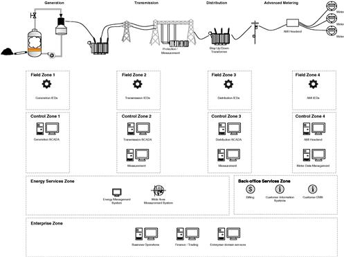
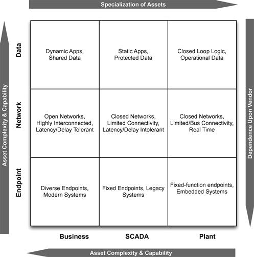
Figure 5.8 The McAfee “3 × 3” security model for critical infrastructure cyber security (source: McAfee, Inc. an Intel Company7).
Each point in the resulting matrix represents unique security challenges, and each requires special consideration when deploying cyber security measures. Not to be overlooked is that—because an attack can easily migrate from one area to the next (see Chapter 3, “Attacking the Smart Grid”)—it is equally important to monitor all nine areas as a cohesive whole. This can represent a challenge of its own due to the need for strong network separation and access controls between zones (see Chapter 6, “Securing the Smart Grid”). Complicating matters further, there are multiple areas in a Smart Grid to which the “3×3” model can be applied, and as shown above, many of these areas are interconnected, creating another dimension of zone definition and separation.
Applying the “3 × 3” cyber security model to Smart Grids
The Smart Grid is made up of many interconnected systems, making it extremely difficult to architect a single security model around the “Smart Grid” as a whole. However, by thinking of the Smart Grid as a conglomerate of component functional groups, the 3 × 3 model can be applied individually to each group. In Figure 5.9, the following functional groups are illustrated: back office, generation, transmission, distribution, and metering, and in-home systems. Each of these areas (with the exception of back office systems) consists of business functions, command functions (SCADA, EMS, etc.), and control functions (the embedded devices or “plant”).
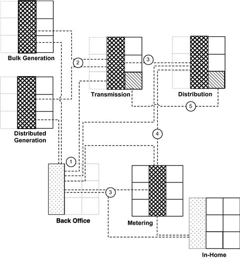
The challenge to cyber security is introduced when these systems are interconnected openly. Various SCADA and management servers will likely be collocated in one or more data centers. Just as likely, these systems will be interconnected via Ethernet, and while a security perimeter will be established around this network, the communication of devices within the network will be largely trusted. Figure 5.9 shows clearly that without a strong degree of access controls between all individual systems, there will be easy communications between any point (including highly accessible field devices in T&D and metering) and SCADA, control, management, measurement and business systems.
Figure 5.9 also illustrates how each area maintains the three primary security concerns expressed within the 3 × 3 security model: endpoint protection, network protection, and data protection, highlighting how certain domains are more heavily weighted toward business, operational or field device zones. This highlights where greater security controls are required and where each zone should focus on device security, network access, and data infiltration and exfiltration.
Back-office systems
Back-office systems—customer management systems, billing, corporate marketing and PR, sales and finance, and other common business system that provide information to and consume data from other Smart Grid systems—typically do not connect directly to SCADA or field devices, but they do connect to other applications and servers in generation, transmission, distribution, and metering. The primary purpose for this connectivity is one of data sharing, and therefore data security needs to be protected to ensure that sensitive data are not stolen or manipulated. In addition, these systems need to be protected against malware (they likely already are, as they are valuable enterprise IT assets). Finally, the authorized network paths between these and other services must be protected via a strong network security policy to ensure that if a back office system is compromised, it cannot be used to access SCADA and management systems elsewhere in the grid, and that the malware will not be able to propagate into these other systems.
Note the connections (1) in Figure 5.9, linking almost every operational service (SCADA or similar control function) within generation, transmission, distribution, and metering system connect to a back-office system. It is therefore extremely important to implement logical controls to separate these systems (if they are different), or to control the access to and use of data used within these systems (if they are shared).
Generation, transmission, distribution and metering systems
Most of the systems used within these domains are command and control management systems: SCADA systems, distribution management systems and demand response systems, meter data management systems, etc. These systems provide key operational capabilities within their domain and provide control over subordinate field devices (RTUs, IEDs, etc.)—all while providing important information to back-office systems. Separating these systems from the back-office systems is a good start, but each of these systems also requires a similar degree of separation from each other. Each must also be separated from other zones within its own functional group, to prevent malware from moving between SCADA systems, management systems, and other “command” infrastructure components—as well as to prevent threats from entering the business areas of each zone from these command environments.
In Figure 5.9, connections (2), (3), and (4) between the operational (SCADA) zones of these systems are illustrated to highlight how the infection of one domain can easily propagate into neighboring domains.
As proven by real-world examples, malware is capable of moving from SCADA to industrial control systems such as PLCs and HMIs, so again all three areas of security are required: endpoint to protect these command components, network protection to control access to them and limit network based exploits, as well as data protection to prevent theft of data or (perhaps more important in these environments) the injection of false data to manipulate or sabotage the control environment.
However, the Smart Grid also introduces several interesting back channels, such as between field devices shown in connection (5) in Figure 5.9. In this example, distributed phasor measurement units (PMUs) communicate to a central system (the PDC). While the PMUs do not communicate directly with each other, they are interdependent upon a common globally available (via GPS) time source for synchronization. Other field devices, such fault indicators, may also interconnect with each other as well as a headend unit of management systems, via GSM or other wireless network.
Generation, transmission, and metering embedded devices
Embedded systems include programmable logic controllers (PLC), remote terminal/telemetry units (RTU), intelligent electronic devices (IED), single-purpose process HMIs, power protection systems, transformers, reclosers, PMUs, Volt/VAR systems, and almost any field device within the Smart Grid that is not a server-based system. In many cases, these devices are also not typically based on a Windows OS. These devices represent the third environment of the “3 × 3” model and are, as previously mentioned, more difficult to secure. However, these systems are susceptible to attacks and must be secured both to (a) protect the devices from direct manipulation or sabotage, and (b) to prevent the use of these widely accessible field devices as an inbound attack vector to other more lucrative systems such as SCADA and back-office systems.
With the exception of distributed measurement (connection (5) in Figure 5.9), most field devices interconnect only with other devices within the same domain, and with corresponding management systems.
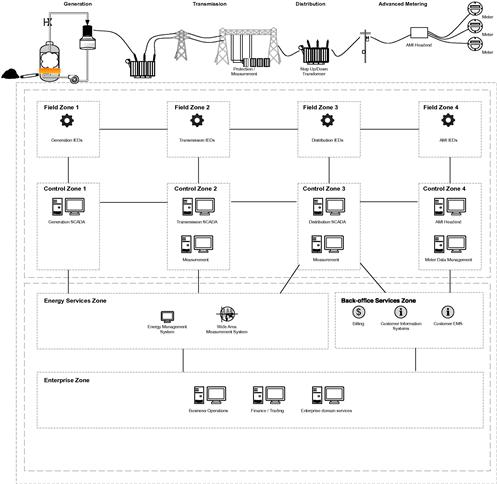
A simplified Smart Grid reference model
Putting all of this together, a new reference model for Smart Grid cyber security can be used to apply the same “zone and conduit” or “enclave separation” security methodology outlined by ISA-62443 and other cyber security standards. While no one architecture is universally applicable (all Smart Grid deployments will different substantially due to their inherent complexity), this reference model illustrated in Figure 5.10 provides a solid foundation upon which to plan, design, and implement the cyber security controls discussed in Chapter 6, “Protecting the Smart Grid.” Note that this reference model is not intended to be all-inclusive: it has been simplified to make it more understandable and so that it can be referenced heavily within Chapter 6 without undue distraction.
Summary
While cyber security methodologies based upon the separation of asset groups and the control of group interconnectivity—such as the methodologies of ISA-62443’s “zone and conduit” and the McAfee “3 × 3” cyber security model—are good practice in general, they can be difficult to apply to a system as broad and highly interconnected as a Smart Grid. By carefully mapping a Smart Grid’s architecture to these methodologies, an adequate security methodology can be achieved, and a workable reference model can be built. This reference model is a useful tool for security planning and implementation, and has been used extensively in Chapter 6, “Protecting the Smart Grid.”
References
1. Knapp Eric D. Industrial network security: securing critical infrastructure networks for smart grid, SCADA, and other industrial control systems. Massachusetts: Syngress; August 29, 2011.
2. The smart grid interoperability panel—cyber security working group. NISTIR 7628 guidelines for smart grid cyber security. Smart grid cyber security strategy, architecture, and high-level requirements, vol. 1. US Department of Commerce, National Institute of Standards and Technologies; August 2010.
3. M. Sa´Nchez Jime´Nez. Smart grid mandate M/490 EN: standardization mandate to european standardisation organisations (ESOs) to support European smart grid deployment. Brussels: European Commission Directorate-General for Energy; March 1, 2011.
4. CEN, CENELEC, ETSI. SGCG report on reference architecture for the smart grid external version V2.0. SGSC Reference Architecture Working Group (RAWG); August, 2012.
5. IEEE Standards Coordinating Committee 21. IEEE Standard 2030™-2011. IEEE guide for smart grid interoperability of energy technology and information technology operation with the electric power system (EPS), end-use applications, and loads. NY, USA: IEEE. September 10, 2011.
6. American National Standard ANSI/ISA–99.00.01–2007. Security for industrial automation and control systems, Part 1: Terminology, concepts, and models. NC: Research Triangle Park; October 2007.
7. Knapp Eric D. Industrial control systems cyber security proof of concept. Presented at the department of homeland security industrial control systems joint working group spring conference, Savannah, Georgia; May 9, 2012.