
1
PACKET ANALYSIS AND NETWORK BASICS

A million different things can go wrong with a computer network on any given day—from a simple spyware infection to a complex router configuration error—and it’s impossible to solve every problem immediately. The best we can hope for is to be fully prepared with the knowledge and tools we need to respond to these types of issues.
To truly understand network problems, we go to the packet level. All network problems stem from this level, where even the prettiest-looking applications can reveal their horrible implementations and seemingly trustworthy protocols can prove malicious. Here, nothing is hidden from us. Nothing is obscured by misleading menu structures, eye-catching graphics, or untrustworthy employees—there are no true secrets (only encrypted ones). The more we can do at the packet level, the more we can control our network and solve problems. This is the world of packet analysis.
This book dives into this world headfirst. Through real-world scenarios, you’ll learn how to tackle slow network communication, identify application bottlenecks, and even track hackers. By the time you’ve finished reading this book, you should be able to implement packet analysis techniques that will help you solve even the most difficult problems in your own network.
In this chapter, we’ll begin with the basics, focusing on network communication. The material here will help you gain the tools you’ll need to examine different scenarios.
Packet Analysis and Packet Sniffers
Packet analysis, often referred to as packet sniffing or protocol analysis, describes the process of capturing and interpreting live data as it flows across a network in order to better understand what is happening on that network. Packet analysis is typically performed by a packet sniffer, a tool used to capture raw network data going across the wire.
Packet analysis can help with the following:
• Understanding network characteristics
• Learning who is on a network
• Determining who or what is utilizing available bandwidth
• Identifying peak network usage times
• Identifying malicious activity
• Finding unsecured and bloated applications
There are various types of packet-sniffing programs, including both free and commercial ones. Each program is designed with different goals in mind. A few popular packet analysis programs are tcpdump, OmniPeek, and Wireshark (we’ll primarily be using Wireshark in this book). OmniPeek and Wireshark have graphical user interfaces (GUIs), while tcpdump is a command line program.
Evaluating a Packet Sniffer
You need to consider a number of factors when selecting a packet sniffer, including the following:
Supported protocols All packet sniffers can interpret various protocols. Most can interpret common network protocols (such as IPv4 and ICMP), transport protocols (such as TCP and UDP), and even application protocols (such as DNS and HTTP). However, they may not support nontraditional, newer, or more complex protocols (such as IPv6, SMBv2, and SIP). When choosing a sniffer, make sure that it supports the protocols you’re going to use.
User friendliness Consider the packet sniffer’s layout, ease of installation, and general workflow. The program you choose should fit your level of expertise. If you have very little packet analysis experience, you may want to avoid the more advanced command line packet sniffers like tcpdump. On the other hand, if you are a packet analysis veteran, you may find an advanced program more useful. As you gain experience, you may even find it useful to combine multiple packet-sniffing programs to fit particular scenarios.
Cost The great thing about packet sniffers is that there are many free ones that rival any commercial products. The most notable difference between commercial products and their free alternatives is their reporting engines. Commercial products typically include some form of fancy report generation module, while free applications either lack this capability or offer only very limited reporting.
Program support Even after you have mastered the basics of a sniffing program, you may occasionally need support to solve new problems as they arise. When evaluating available support, look for developer documentation, public forums, and mailing lists. Although there may be a lack of formalized commercial support for free packet-sniffing programs like Wireshark, communities of users and contributors often provide active discussion boards, wikis, and blogs to help you get more out of your packet sniffer.
Source code access Some packet sniffers are open source software. This means that you can view the source code of the program and, in some cases, even suggest and make changes to that source code. If you have a very specific or advanced use case for a sniffing application, this might be an appealing feature. Most commercial applications don’t provide source code access.
Operating system support Unfortunately, not all packet sniffers support every operating system. Choose one that will work on all the operating systems that you need to support. If you are a consultant, you may be required to capture and analyze packets on a variety of operating systems, so you’ll need a tool that runs on most of them. Also, keep in mind that you’ll sometimes capture packets on one machine and review them on another. Variations between operating systems may force you to use a different application for each device.
How Packet Sniffers Work
The packet-sniffing process involves a cooperative effort between software and hardware. This process can be broken down into three steps:
Collection: First, the packet sniffer collects raw binary data from the wire. Typically this is done by switching the selected network interface into promiscuous mode. In this mode, the network card can listen to all traffic on a network segment, not only the traffic that is addressed to it.
Conversion: Next, the captured binary data is converted into a readable form. This is as far as most advanced command line packet sniffers can go. At this point, the network data can be interpreted only on a very basic level, leaving the majority of the analysis to the end user.
Analysis: Finally, the packet sniffer conducts an analysis of the captured and converted data. The sniffer verifies the protocol of the captured network data based on the information extracted and begins its analysis of that protocol’s specific features.
How Computers Communicate
To fully understand packet analysis, you must know exactly how computers communicate with each other. In this section, we’ll examine the basics of network protocols, the Open Systems Interconnections (OSI) model, network data frames, and the hardware that supports it all.
Protocols
Modern networks are made up of a variety of systems running on many different platforms. To communicate between systems, we use a set of common languages called protocols. Common protocols include Transmission Control Protocol (TCP), Internet Protocol (IP), Address Resolution Protocol (ARP), and Dynamic Host Configuration Protocol (DHCP). A logical grouping of protocols that work together is called a protocol stack.
It might help to think of protocols as similar to the rules that govern human language. Every language has rules such as how to conjugate verbs, how to greet people, and even how to properly thank someone. Protocols work in much the same fashion, allowing us to define how packets should be routed, how to initiate a connection, and how to acknowledge the receipt of data.
A protocol can be extremely simple or highly complex, depending on its function. Although the various protocols can differ significantly, many protocols address the following issues:
Connection initiation Is it the client or server initiating the connection? What information must be exchanged prior to communication?
Negotiation of connection characteristics Is the communication of the protocol encrypted? How are encryption keys transmitted between communicating hosts?
Data formatting How is the data contained within the packet organized? In what order is the data processed by the devices receiving it?
Error detection and correction What happens in the event that a packet takes too long to reach its destination? How does a client recover if it cannot establish communication with a server for a short duration?
Connection termination How does one host signify to the other that communication has ended? What final information must be transmitted in order to gracefully terminate communication?
The Seven-Layer OSI Model
Protocols are separated according to their functions based on the industry-standard OSI reference model. This hierarchical model, with seven distinct layers, is very helpful for understanding network communications. In Figure 1-1, the layers of the OSI model are on the right, and the proper terminology for data at each of these layers is on the left. The application layer at the top represents the programs used to access network resources. The bottom layer is the physical layer, through which the network data travels. The protocols at each layer work together to ensure data is properly handled by the protocols at layers directly above and below.
NOTE
The OSI model was originally published in 1983 by the International Organization for Standardization (ISO) as a document called ISO 7498. The OSI model is no more than an industry-recommended standard. Protocol developers are not required to follow it exactly. In fact, the OSI model is not the only networking model; for example, some people prefer the Department of Defense (DoD) model, also known as the TCP/IP model.

Figure 1-1: A hierarchical view of the seven layers of the OSI model
Each OSI model layer has a specific function, as follows:
Application layer (layer 7) The topmost layer of the OSI model provides a means for users to access network resources. This is the only layer typically seen by end users, as it provides the interface that is the base for all of their network activities.
Presentation layer (layer 6) This layer transforms the data it receives into a format that can be read by the application layer. The data encoding and decoding done here depends on the application layer protocol that is sending or receiving the data. The presentation layer also handles several forms of encryption and decryption used to secure data.
Session layer (layer 5) This layer manages the dialogue, or session, between two computers. It establishes, manages, and terminates this connection among all communicating devices. The session layer is also responsible for establishing whether a connection is duplex (two-way) or half-duplex (one-way) and for gracefully closing a connection between hosts rather than dropping it abruptly.
Transport layer (layer 4) The primary purpose of the transport layer is to provide reliable data transport services to lower layers. Through flow control, segmentation/desegmentation, and error control, the transport layer makes sure data gets from point to point error-free. Because ensuring reliable data transportation can be extremely cumbersome, the OSI model devotes an entire layer to it. The transport layer utilizes both connection-oriented and connectionless protocols. Certain firewalls and proxy servers operate at this layer.
Network layer (layer 3) This layer, one of the most complex of the OSI layers, is responsible for routing data between physical networks. It sees to the logical addressing of network hosts (for example, through an IP address). It also handles splitting data streams into smaller fragments and, in some cases, error detection. Routers operate at this layer.
Data link layer (layer 2) This layer provides a means of transporting data across a physical network. Its primary purpose is to provide an addressing scheme that can be used to identify physical devices (for example, MAC addresses). Bridges and switches are physical devices that operate at the data link layer.
Physical layer (layer 1) The layer at the bottom of the OSI model is the physical medium through which network data is transferred. This layer defines the physical and electrical nature of all hardware used, including voltages, hubs, network adapters, repeaters, and cabling specifications. The physical layer establishes and terminates connections, provides a means of sharing communication resources, and converts signals from digital to analog and vice versa.
NOTE
A common mnemonic device for remembering the layers of the OSI model is Please Do Not Throw Sausage Pizza Away. The first letter of each word refers to each layer of the OSI model, starting with the first layer.
Table 1-1 lists some of the more common protocols used at each layer of the OSI model.
Table 1-1: Typical Protocols Used at Each Layer of the OSI Model
Layer |
Protocols |
Application |
HTTP, SMTP, FTP, Telnet |
Presentation |
ASCII, MPEG, JPEG, MIDI |
Session |
NetBIOS, SAP, SDP, NWLink |
Transport |
TCP, UDP, SPX |
Network |
IP, IPX |
Data link |
Ethernet, Token Ring, FDDI, AppleTalk |
Physical |
wired, wireless |
Although the OSI model is no more than a recommended standard, you should know it by heart as it provides a useful vocabulary for thinking about and describing network problems. As we progress through this book, you will find that router issues soon become “layer 3 problems” and software issues are readily recognized as “layer 7 problems.”
NOTE
A colleague once told me about a user who complained that he could not access a network resource. The issue was the result of the user’s entering an incorrect password. My colleague referred to this as a layer 8 issue. Layer 8 is the unofficial user layer. This term is commonly used among those who live at the packet level.
Data Flow Through the OSI Model
The initial data transfer on a network begins at the application layer of the transmitting system. Data works its way down the seven layers of the OSI model until it reaches the physical layer, at which point the physical layer of the transmitting system sends the data to the receiving system. The receiving system picks up the data at its physical layer, and the data proceeds up the layers of the receiving system to the application layer at the top.
Each layer in the OSI model is capable of communicating only with the layers directly above and below it. For example, layer 2 can send and receive data only from layers 1 and 3.
None of the services provided by various protocols at any given level of the OSI is redundant. For example, if a protocol at one layer provides a particular service, then no other protocol at any other layer will provide this same service. Protocols at different levels may have features with similar goals, but they will function a bit differently.
Protocols at corresponding layers on the sending and receiving devices are complementary. So, for example, if a protocol at layer 7 of the sending device is responsible for formatting the data being transmitted, the corresponding protocol at layer 7 of the receiving device is expected to be responsible for reading that formatted data.
Figure 1-2 is a graphical representation of the OSI model as it relates to two communicating devices. You can see communication going from top to bottom on one device and then reversing when it reaches the second device.

Figure 1-2: Protocols working at the same layer on both the sending and receiving systems
Data Encapsulation
The protocols at different layers of the OSI model pass data between each other with the aid of data encapsulation. Each layer in the stack is responsible for adding a header or footer—extra bits of information that allow the layers to communicate—to the data being transferred. For example, when the transport layer receives data from the session layer, the transport layer adds its own header information to that data before passing it to the network layer.
The encapsulation process creates a protocol data unit (PDU), which includes the data being sent and all header or footer information added to it. As data moves down the OSI model and the various protocols add header and footer information, the PDU changes and grows. The PDU is in its final form when it reaches the physical layer, at which point it is sent to the destination device. The receiving device strips the protocol headers and footers from the PDU as the data climbs up the OSI layers in the reverse of the order they were added. Once the PDU reaches the top layer of the OSI model, only the original application layer data remains.
NOTE
The OSI model uses specific terms to describe packaged data at each layer. The physical layer contains bits, the data link layer contains frames, the network layer contains packets, and the transport layer contains segments. The top three layers simply use the term data. This nomenclature isn’t used much in practice, so we’ll generally just use the term packet to refer to a complete or partial PDU that includes header and footer information from a few or many layers of the OSI model.
To illustrate how encapsulation of data works, we’ll look at a simplified practical example of a packet being built, transmitted, and received in relation to the OSI model. Keep in mind that as analysts, we don’t often talk about the session or presentation layers, so those will be absent in this example (and the rest of this book).
In this scenario, we are attempting to browse to http://www.google.com/. First, we must generate a request packet that is transmitted from our source client computer to the destination server computer. This scenario assumes that a TCP/IP communication session has already been initiated. Figure 1-3 illustrates the data encapsulation process in this example.
We begin on our client computer at the application layer. We are browsing to a website, so the application layer protocol being used is HTTP; the HTTP protocol will issue a command to download the file index.html from google.com.
NOTE
In practice, the browser will request the website document root first, signified by a forward slash (/). When the web server receives this request, it will redirect the browser to whatever file it is configured to serve upon receiving a document root request. This is usually something like index.html or index.php. We’ll cover this more in Chapter 9 when we discuss HTTP.
Once our application layer protocol has sent the command, our concern is with getting the packet to its destination. The data in our packet is passed down the OSI stack to the transport layer. HTTP is an application layer protocol that uses (or sits on) TCP, so TCP serves as the transport layer protocol used to ensure reliable delivery of the packet. A TCP header is generated and added to the PDU, as shown in the transport layer of Figure 1-3. This TCP header includes sequence numbers and other data that are appended to the packet, ensuring that the packet is properly delivered.
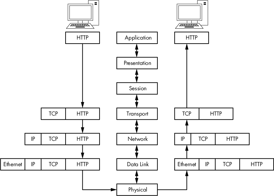
Figure 1-3: A graphical representation of encapsulation of data between client and server
NOTE
We often say that one protocol “sits on” or “rides on” another protocol because of the top-down design of the OSI model. An application protocol such as HTTP provides a particular service and relies on TCP to ensure reliable delivery of its service. Both of those services rely on the IP protocol at the network level to address and deliver their data. Therefore, HTTP sits on TCP, which sits on IP.
Having done its job, TCP hands the packet off to IP, which is the layer 3 protocol responsible for the logical addressing of the packet. IP creates a header containing logical addressing information, adds it to the PDU, and passes the packet along to the Ethernet on the data link layer. Physical Ethernet addresses are stored in the Ethernet header. The packet is now fully assembled and passed to the physical layer, where it is transmitted as zeros and ones across the network.
The completed packet traverses the network cabling system, eventually reaching the Google web server. The web server begins by reading the packet from the bottom up, meaning that it first reads the data link layer, which contains the physical Ethernet addressing information that the network card uses to determine that the packet is intended for a particular server. Once this information is processed, the layer 2 information is stripped away, and the layer 3 information is processed.
The layer 3 IP addressing information is read to ensure that the packet is properly addressed and is not fragmented. This data is also stripped away so that the next layer can be processed.
Layer 4 TCP information is now read to ensure that the packet has arrived in sequence. Then the layer 4 header information is stripped away to leave only the application layer data, which can be passed to the web server application hosting the website. In response to this packet from the client, the server should transmit a TCP acknowledgment packet so the client knows its request was received, followed by the index.html file.
All packets are built and processed as described in this example, regardless of which protocols are used. But at the same time, keep in mind that not every packet on a network is generated from an application layer protocol, so you will see packets that contain only information from layer 2, 3, or 4 protocols.
Network Hardware
Now it’s time to look at network hardware, where the dirty work is done. We’ll focus on just a few of the more common pieces of network hardware: hubs, switches, and routers.
Hubs
A hub is generally a box with multiple RJ-45 ports, like the NETGEAR hub shown in Figure 1-4. Hubs range from very small 4-port devices to larger 48-port devices designed for rack mounting in a corporate environment.

Figure 1-4: A typical 4-port Ethernet hub
Because hubs can generate a lot of unnecessary network traffic and are capable of operating only in half-duplex mode (they cannot send and receive data at the same time), you won’t typically see them used in most modern or high-density networks; switches are used instead (discussed in the next section). However, you should know how hubs work, since they will be very important to packet analysis when using the “hubbing out” technique discussed in Chapter 2.
A hub is no more than a repeating device that operates on the physical layer of the OSI model. It takes packets sent from one port and transmits (repeats) them to every other port on the device, and it’s up to the receiving device to accept or reject each packet. For example, if a computer on port 1 of a 4-port hub needs to send data to a computer on port 2, the hub sends those packets to ports 2, 3, and 4. The clients connected to ports 3 and 4 examine the destination Media Access Control (MAC) address field in the Ethernet header of the packet and see that the packet is not for them, so they drop (discard) the packet. Figure 1-5 illustrates an example in which computer A is transmitting data to computer B. When computer A sends this data, all computers connected to the hub receive it. However, only computer B actually accepts the data; the other computers discard it.

Figure 1-5: The flow of traffic when computer A transmits data to computer B through a hub
As an analogy, suppose that you sent an email with the subject line “Attention all marketing staff” to every employee in your company, rather than to only those people who work in the marketing department. The marketing department employees see the email is for them and open it. The other employees see it’s not for them and discard it. You can see how this approach to communication would result in a lot of unnecessary traffic and wasted time, yet this is exactly how a hub functions.
The best alternatives to hubs in production and high-density networks are switches, which are full-duplex devices that can send and receive data synchronously.
Switches
Like a hub, a switch is designed to repeat packets. However, unlike a hub, rather than broadcasting data to every port, a switch sends data to only the computer for which the data is intended. Switches look just like hubs, as shown in Figure 1-6.

Figure 1-6: A rack-mountable 48-port Ethernet switch
Several larger switches on the market, such as Cisco-branded ones, are managed via specialized, vendor-specific software or web interfaces. These switches are commonly referred to as managed switches. Managed switches provide several features that can be useful in network management, including the ability to enable or disable specific ports, view port statistics, make configuration changes, and remotely reboot.
Switches also offer advanced functionality for handling transmitted packets. To be able to communicate directly with specific devices, switches must be able to uniquely identify devices based on their MAC addresses, which means that they must operate on the data link layer of the OSI model.
Switches store the layer 2 address of every connected device in a CAM table, which acts as a kind of traffic cop. When a packet is transmitted, the switch reads the layer 2 header information in the packet and, using the CAM table as reference, determines to which port(s) to send the packet. Switches send packets only to specific ports, thus greatly reducing network traffic.
Figure 1-7 illustrates traffic flow through a switch. In this figure, computer A is sending data to only the intended recipient: computer B. Multiple conversations can happen on the network at the same time, but information is communicated directly between the switch and intended recipient, not between the switch and all connected computers.

Figure 1-7: The flow of traffic when computer A transmits data to computer B through a switch
Routers
A router is an advanced network device with a much higher level of functionality than a switch or a hub. A router can take many shapes and forms, but most devices have several LED indicator lights on the front and a few network ports on the back, depending on the size of the network. Figure 1-8 shows an example of a small router.
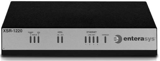
Figure 1-8: A low-level Enterasys router suitable for use in a small to midsized network
Routers operate at layer 3 of the OSI model, where they are responsible for forwarding packets between two or more networks. The process used by routers to direct the flow of traffic among networks is called routing. Several types of routing protocols dictate how different types of packets are routed to other networks. Routers commonly use layer 3 addresses (such as IP addresses) to uniquely identify devices on a network.
A good way to illustrate the concept of routing is to use the analogy of a neighborhood with several streets. Think of the houses, with their addresses, as computers. Then think of each street as a network segment. Figure 1-9 illustrates this comparison. From your house, you can easily go visit your neighbors in the other houses on the same street by walking in a straight line from your front door to theirs. In the same way, a switch allows communication among all computers on a network segment.
However, communicating with a neighbor who lives on another street is like communicating with a computer that is not on the same segment. Referring to Figure 1-9, let’s say that you’re sitting at 502 Vine Street and need to get to 206 Dogwood Lane. In order to do this, you must first turn onto Oak Street and then turn onto Dogwood Lane. Think of this as crossing network segments. If the device at 192.168.0.3 needs to communicate with the device at 192.168.0.54, it must cross a router to get to the 10.100.1.x network and then cross the destination network segment’s router before it can get to the destination network segment.
The size and number of routers on a network will typically depend on the network’s size and function. Personal and home office networks may have only a small router located at the edge of the network. A large corporate network might have several routers spread throughout various departments, all connecting to one large central router or layer 3 switch (an advanced type of switch that also has built-in functionality to act as a router).
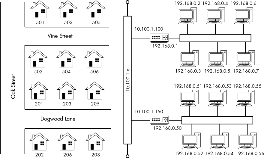
Figure 1-9: Comparison of a routed network to neighborhood streets
As you look at more and more network diagrams, you will come to understand how data flows through these various points. Figure 1-10 shows the layout of a very common form of routed network. In this example, two separate networks are connected via a single router. If a computer on network A wishes to communicate with a computer on network B, the transmitted data must go through the router.

Figure 1-10: The flow of traffic when computer A on one network transmits data to computer X on another network through a router
Traffic Classifications
Network traffic can be classified as one of three types: broadcast, multicast, and unicast. Each classification has a distinct characteristic that determines how packets in that class are handled by networking hardware.
Broadcast Traffic
A broadcast packet is a packet that’s sent to all ports on a network segment, regardless of whether a given port is a hub or switch.
There are layer 2 and layer 3 forms of broadcast traffic. On layer 2, the MAC address ff:ff:ff:ff:ff:ff is the reserved broadcast address, and any traffic sent to this address is broadcast to the entire network segment. Layer 3 also has a specific broadcast address, but it varies based on the network address range in use.
The highest possible IP address in an IP network range is reserved for use as the broadcast address. For example, if your computer has an address of 192.168.0.20 and a 255.255.255.0 subnet mask, then 192.168.0.255 is the broadcast address (more on IP addressing in Chapter 7).
The extent to which broadcast packets can travel is called the broadcast domain, which is the network segment where any computer can directly transmit to another computer without going through a router. In larger networks with multiple hubs or switches connected via different media, broadcast packets transmitted from one switch reach all the ports on all the other switches on the network, as the packets are repeated from switch to switch. Figure 1-11 shows an example of two broadcast domains on a small network. Because each broadcast domain extends until it reaches the router, broadcast packets circulate only within this specified broadcast domain.
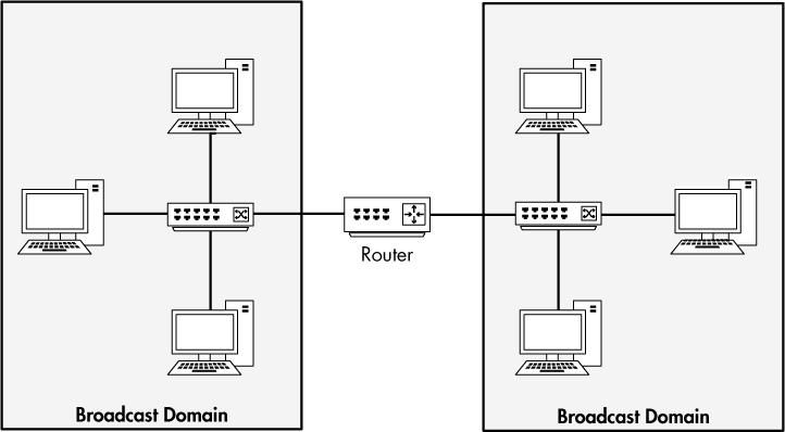
Figure 1-11: A broadcast domain extends to everything behind the current routed segment.
Our earlier neighborhood analogy provides good insight into how broadcast domains work, too. You can think of a broadcast domain as being like a neighborhood street where all your neighbors are sitting on their front porch. If you stand on your front porch and yell, the people on your street will be able to hear you. However, if you want to talk to someone on a different street, you need to find a way to speak to that person directly, rather than broadcasting (yelling) from your front porch.
Multicast Traffic
Multicast is a means of transmitting a packet from a single source to multiple destinations simultaneously. The goal of multicasting is to use as little bandwidth as possible. The optimization of this traffic lies in that a stream of data is replicated fewer times along its path to its destination. The exact handling of multicast traffic is highly dependent on its implementation in individual protocols.
The primary method of implementing multicast traffic is via an addressing scheme that joins the packet recipients to a multicast group. This is how IP multicast works. This addressing scheme ensures that the packets cannot be transmitted to computers to which the packets are not destined. In fact, IP devotes an entire range of addresses to multicast. If you see an IP address in the 224.0.0.0 to 239.255.255.255 range, it is most likely handling multicast traffic because these ranges are reserved for that purpose.
Unicast Traffic
A unicast packet is transmitted from one computer directly to another. The details of how unicast functions are dependent on the protocol using it. For example, consider a device that wishes to communicate with a web server. This is a one-to-one connection, so this communication process would begin with the client device transmitting a packet to only the web server.
Final Thoughts
This chapter covered the basics of networking that you need as a foundation for packet analysis. You must understand what is going on at this level of network communication before you can begin troubleshooting network issues. In Chapter 2, we will look at multiple techniques for capturing the packets you want to analyze.