
13
WIRELESS PACKET ANALYSIS

The world of wireless networking is a bit different from that of traditional wired networking. Although we are still dealing with common communication protocols such as TCP and IP, the game changes a bit when moving to the lowest levels of the OSI model. Here, the data link layer is of special importance due to the nature of wireless networking and the physical layer. Instead of simple wired protocols such as Ethernet, which haven’t changed much over time, we have to consider the nuances of wireless protocols such as 802.11, which have evolved pretty quickly. This puts new restrictions on the data we access and how we capture it.
Given these extra considerations, it should come as no surprise that an entire chapter of this book is dedicated to packet capture and analysis on wireless networks. In this chapter, we will discuss exactly why wireless networks are unique when it comes to packet analysis and how to overcome any challenges. Of course, we will be doing this by looking at actual practical examples of wireless network captures.
Physical Considerations
The first thing to consider about capturing and analyzing data transmitted across a wireless network is the physical transmission medium. Until now, we haven’t considered the physical layer because we’ve been communicating over physical cabling. Now we’re communicating through invisible airwaves, with packets flying right by us.
Sniffing One Channel at a Time
A consideration distinct to capturing traffic from a wireless local area network (WLAN) is that the wireless spectrum is a shared medium. Unlike wired networks, where each client has its own network cable connected to a switch, the wireless communication medium is the airspace clients share, which is limited in size. A single WLAN will occupy only a portion of the 802.11 spectrum. This allows multiple systems to operate in the same physical area on different portions of the spectrum.
NOTE
Wireless networking is based on the 802.11 standard, developed by the Institute of Electrical and Electronics Engineers (IEEE). Throughout this chapter, the terms wireless network and WLAN refer to networks that adhere to the 802.11 standard. The most popular versions of this standard are 802.11a, b, g, and n. Each offers a unique set of features and characteristics, with newer standards such as n offering faster speed. They all still use the same spectrum.
This separation of space is made possible by dividing the spectrum into operation channels. A channel is simply a portion of the 802.11 wireless spectrum. In the United States, 11 channels are available (more are allowed in some other countries). This is relevant because, just as a WLAN can operate on only one channel at a time, we can sniff packets on only one channel at a time, as illustrated in Figure 13-1. Therefore, if you are troubleshooting a WLAN operating on channel 6, you must configure your system to capture traffic seen on channel 6.

Figure 13-1: Sniffing wirelessly can be tedious, since it can be done on only one channel at a time.
Traditional wireless sniffing can only be done one channel at a time, with an exception: certain wireless scanning applications use a technique called channel hopping to change channels rapidly in order to collect data. One of the most popular tools of this type, Kismet (http://www.kismetwireless.net/), can hop up to 10 channels per second, a capability that makes it very effective at sniffing multiple channels at once.
Wireless Signal Interference
With wireless communications, we sometimes can’t rely on the integrity of the data being transmitted over the air. It’s possible that something will interfere with the signal. Wireless networks include some features to handle interference, but those features don’t always work. Therefore, when capturing packets over a wireless network, you must pay close attention to your environment to ensure that there are no significant sources of interference, such as big reflective surfaces, large rigid objects, microwaves, 2.4 GHz phones, thick walls, or high-density surfaces. These can cause packet loss, duplicated packets, and malformed packets.
Interference between channels is also a concern. Although you can sniff only one channel at a time, this comes with a small caveat: several transmission channels are available in the wireless networking spectrum, but because space is limited, there is a slight overlap between channels, as illustrated in Figure 13-2. This means that if there is traffic present on channel 4 and channel 5, and you are sniffing on one of these channels, you will likely capture packets from the other channel. Typically, networks that coexist in the same area are designed to use nonoverlapping channels of 1, 6, and 11, so you probably won’t encounter this problem. But just in case, you should understand why it happens.
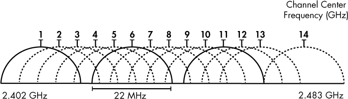
Figure 13-2: There is overlap between channels due to limited spectrum space.
Detecting and Analyzing Signal Interference
Troubleshooting wireless signal interference isn’t something that can be done by looking at packets in Wireshark. If you are going to make a habit or a career out of troubleshooting WLANs, you will surely need to check for signal interference regularly. This task is done with a spectrum analyzer, a tool that displays data or interference across the spectrum.
Commercial spectrum analyzers can cost upward of thousands of dollars, but there is a great solution for common everyday use. MetaGeek makes a USB hardware device, the Wi-Spy, that monitors the entire 802.11 spectrum for signals. When paired with MetaGeek’s inSSIDer or Chanalyzer software, this hardware outputs the spectrum graphically to aid in the troubleshooting process. Sample output from Chanalyzer is shown in Figure 13-3.

Figure 13-3: This Chanalyzer output shows four signals equally spaced along the Wi-Fi spectrum.
Wireless Card Modes
Before we start sniffing wireless packets, we need to look at the different modes in which a wireless card can operate as it pertains to packet capture.
Four wireless NIC modes are available:
Managed mode This mode is used when your wireless client connects directly to a wireless access point (WAP). In these cases, the driver associated with the wireless NIC relies on the WAP to manage the entire communication process.
Ad hoc mode This mode is used when you have a wireless network setup in which devices connect directly to each other. In this mode, two wireless clients that want to communicate with each other share the responsibilities that a WAP would normally handle.
Master mode Some higher-end wireless NICs also support master mode. This mode allows the wireless NIC to work in conjunction with specialized driver software in order to allow the computer to act as a WAP for other devices.
Monitor mode This is the most important mode for our purposes. Monitor mode is used when you want your wireless client to stop transmitting and receiving data and instead only listen to the packets flying through the air. For Wireshark to capture wireless packets, your wireless NIC and accompanying driver must support monitor mode (also known as RFMON mode).
Most users use wireless cards in only managed mode or ad hoc mode. A graphical representation of the way each mode operates is shown in Figure 13-4.
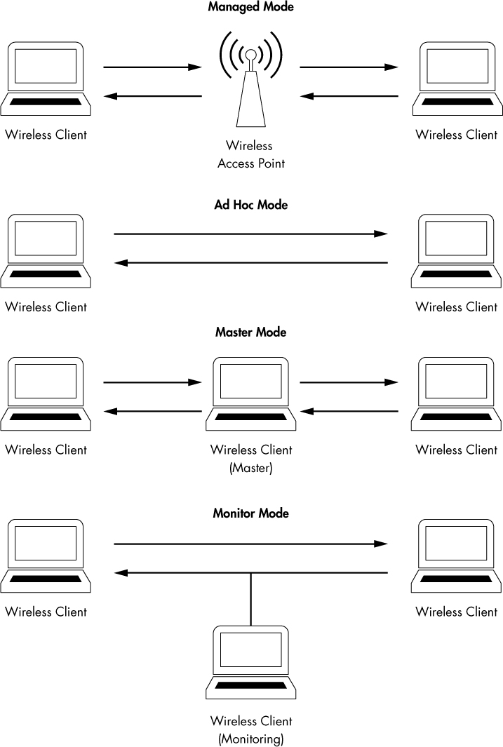
Figure 13-4: The different wireless card modes
NOTE
I’m often asked which wireless card I recommend for wireless packet analysis. I use and highly recommend products from ALFA network. Their products are regarded as some of the best on the market for ensuring you are capturing every possible packet, and they’re cost-effective and portable. ALFA’s products are available through most online computer hardware retailers.
Sniffing Wirelessly in Windows
Even if you have a wireless NIC that supports monitor mode, most Windows-based wireless NIC drivers won’t allow you to change into this mode. This means that you’ll only be able to capture packets to and from the wireless interface on the device you’re using to connect to the network. To capture packets between all devices on a channel, you’ll need extra hardware.
Configuring AirPcap
AirPcap from Riverbed Technologies (http://www.riverbed.com/) is designed to overcome the limitations that Windows places on wireless packet analysis. AirPcap is a small USB device that resembles a flash drive, as shown in Figure 13-5. It is designed to capture wireless traffic from one or more specified channels. AirPcap uses the WinPcap driver and a special client configuration utility.

Figure 13-5: The AirPcap device is very compact, making it easy to tote along with a laptop.
The AirPcap configuration program (shown in Figure 13-6) is simple to use, with only a few configurable options:
Interface You can select the device you are using for your capture here. Some advanced analysis scenarios may require you to use more than one AirPcap device to sniff simultaneously on multiple channels.
Blink Led Clicking this button will make the LED lights on the AirPcap device blink. This is primarily used to identify the specific adapter you are using if you have multiple AirPcap devices.
Channel In this field, you select the channel you want AirPcap to listen on.

Figure 13-6: The AirPcap configuration program
Extension Channel Here you can select an extension channel, a feature of 802.11n adapters allowing for the creation of wider channels.
Include 802.11 FCS in Frames By default, some systems strip the last four checksum bits from wireless packets. This checksum, known as a frame check sequence (FCS), is used to ensure that packets have not been corrupted during transmission. Unless you have a specific reason to do otherwise, check this box to include the FCS checksums.
Capture Type The three options here are 802.11 Only, 802.11 + Radio, and 802.11 + PPI. The 802.11 Only option includes the standard 802.11 packet header on all captured packets. The 802.11 + Radio option includes this header and prepends it with a radiotap header, which contains additional information about the packet, such as data rate, frequency, signal level, and noise level. The 802.11 + PPI option adds the Per-Packet Information Header, which contains additional information about 802.11n packets.
FCS Filter Even if you uncheck the Include 802.11 FCS in Frames box, this option lets you filter out packets that FCS determines are corrupted. Use the Valid Frames option to show only those packets that FCS thinks can be received successfully.
WEP Configuration This area (accessible on the Keys tab of the AirPcap Control Panel) allows you to enter WEP decryption keys for the networks you will be sniffing. To be able to interpret data encrypted by WEP, you will need to enter the correct WEP keys into this field. WEP keys are discussed in “Successful WEP Authentication” on page 309.
Capturing Traffic with AirPcap
Once you have AirPcap installed and configured, the capture process should be familiar to you. Just start up Wireshark and select the AirPcap interface to start collecting packets from it (Figure 13-7).

Figure 13-7: Selecting the AirPcap interface to capture packets
Remember that you will be capturing packets from whatever channel you selected in the AirPcap configuration utility. If you don’t see the packets you’re looking for, it’s probably because you’re looking on the wrong channel. Change the channel by stopping the active capture, selecting a new channel in the AirPcap configuration utility, and restarting the capture. You can’t actively capture packets while you attempt to change the channel.
If you need to verify what channel you’re capturing from within Wireshark, an easy way is to view wireless capture statistics. Do this by clicking Wireless ▶ WLAN Traffic from the main drop-down menu. The resulting window will show you the devices that were observed and information about them, including the 802.11 channel, as shown in Figure 13-8.
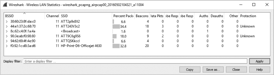
Figure 13-8: The Wireless LAN Statistics window indicates this data was captured by listening to channel 11.
Sniffing Wirelessly in Linux
Sniffing in Linux is simply a matter of enabling monitor mode on the wireless NIC and firing up Wireshark. Unfortunately, the procedure for enabling monitor mode differs with each model of wireless NIC, so I can’t offer definitive advice for doing this. In fact, some wireless NICs don’t require you to enable monitor mode. Your best bet is to do a quick Google search for your NIC model to determine whether you need to enable it and, if so, how.
One of the more common ways to enable monitor mode in Linux is through its built-in wireless extensions. You can access these wireless extensions with the iwconfig command. If you type iwconfig from the console, you should see results like this:
$ iwconfig
➊ Eth0 no wireless extensions
Lo0 no wireless extensions
➋ Eth1 IEEE 802.11g ESSID: "Tesla Wireless Network"
Mode: Managed Frequency: 2.462 GHz Access Point: 00:02:2D:8B:70:2E
Bit Rate: 54 Mb/s Tx-Power-20 dBm Sensitivity=8/0
Retry Limit: 7 RTS thr: off Fragment thr: off
Power Management: off
Link Quality=75/100 Signal level=-71 dBm Noise level=-86 dBm
Rx invalid nwid: 0 Rx invalid crypt: 0 Rx invalid frag: 0
Tx excessive retries: 0 Invalid misc: 0 Missed beacon: 2
The output from the iwconfig command shows that the Eth1 interface can be configured wirelessly. This is apparent because it shows data for the 802.11g protocol ➋, whereas the interfaces Eth0 and Lo0 return the phrase no wireless extensions ➊.
Along with all the wireless information this command provides, such as the wireless extended service set ID (ESSID) and frequency, notice that the second line under Eth1 shows that the mode is currently set to managed. This is what we want to change.
To change the Eth1 interface to monitor mode, you must be logged in as the root user, either directly or via the switch user (su) command, as shown here:
$ su
Password: <enter root password here>
Once you’re root, you can type commands to configure the wireless interface options. To configure Eth1 to operate in monitor mode, enter this:
# iwconfig eth1 mode monitor
Once the NIC is in monitor mode, running the iwconfig command again should reflect your changes. Now ensure that the Eth1 interface is operational by entering the following:
# iwconfig eth1 up
We’ll also use the iwconfig command to change the channel we are listening on. Change the channel of the Eth1 interface to channel 3 by entering this:
# iwconfig eth1 channel 3
NOTE
You can change channels on the fly as you are capturing packets, so don’t hesitate to do so at will. The iwconfig command can also be scripted to make the process easier.
When you have completed these configurations, start Wireshark and begin your packet capture.
802.11 Packet Structure
80211beacon.pcapng
The primary difference between wireless and wired packets is the addition of the 802.11 header. This layer 2 header contains extra information about the packet and the medium by which it is transmitted. There are three types of 802.11 packets:
Management These packets are used to establish connectivity between hosts at layer 2. Some important subtypes of management packets include authentication, association, and beacon packets.
Control Control packets allow for delivery of management and data packets, and they are concerned with congestion management. Common subtypes include request-to-send and clear-to-send packets.
Data These packets contain actual data and are the only types of packets that can be forwarded from the wireless network to the wired network.
The type and subtype of a wireless packet determine its structure, so there are a large number of possible structures. We’ll examine one such structure by looking at a single packet in the file 80211beacon.pcapng. This file contains an example of a management packet called a beacon, as shown in Figure 13-9.
A beacon is one of the most informative wireless packets you can find. It is sent as a broadcast packet from a WAP across a wireless channel to notify any listening wireless clients that the WAP is available and to define the parameters that must be set in order to connect to it. In our example file, you can see that this packet is defined as a beacon in the Type/Subtype field in the 802.11 header ➊.
A great deal of additional information is found in the 802.11 management frame header, including the following:
Timestamp The time the packet was transmitted
Beacon Interval The interval at which the beacon packet is retransmitted
Capabilities Information Information about the hardware capabilities of the WAP

Figure 13-9: This is an 802.11 beacon packet.
SSID parameter set The SSID (network name) broadcast by the WAP
Supported Rates The data transfer rates supported by the WAP
DS Parameter set The channel on which the WAP is broadcasting
The header also includes the source and destination addresses and vendor-specific information.
Based on this, we can determine quite a few things about the WAP transmitting the beacon in the example file. It is apparent that it is a D-Link device ➋ using the 802.11b standard (B) ➌ on channel 11 ➍.
Although the exact contents and purpose of 802.11 management packets will change, the general structure remains similar to this example.
Adding Wireless-Specific Columns to the Packet List Pane
In previous chapters, we’ve leveraged Wireshark’s flexible interface to add situationally appropriate columns. Before we proceed with any additional wireless analysis, it will be helpful to add the following three columns to the Packet List pane.
• The Channel column, to show the channel on which the packet was collected
• The Signal Strength column, to show the signal strength of a captured packet in dBm
• The Data Rate column, to show the throughput rate of a captured packet
These indicators can be of great help when troubleshooting wireless connections. For instance, even if your wireless client software says you have excellent signal strength, doing a capture and checking these columns may show you a number that does not support this claim.
To add these columns to the Packet List pane, follow these steps:
Choose Edit ▶ Preferences.
Navigate to the Columns section and click +.
Type Channel in the Title field, select Custom in the Type drop-down list, and use the filter wlan_radio.channel in the Field Name box.
Repeat this process for the Signal Strength and Data Rate columns, titling them appropriately and selecting wlan_radio.signal_dbm and wlan_radio.data_rate, respectively, in the Field Name drop-down list. Figure 13-10 shows what the Preferences window should look like after you have added all three columns.
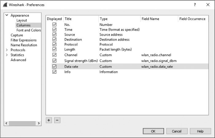
Figure 13-10: Adding the IEEE wireless-specific columns in the Packet List pane
Click OK to save your changes.
Wireless-Specific Filters
We discussed the benefits of capture and display filters in Chapter 4. Filtering traffic in a wired infrastructure is a lot easier since each device has its own dedicated cable. In a wireless network, however, all traffic generated by wireless clients coexists on shared channels, meaning that a capture of any one channel may contain traffic from dozens of clients. This section is devoted to some packet filters that can be used to help you find specific traffic.
Filtering Traffic for a Specific BSS ID
Each WAP in a network has a unique identifying name called its basic service set identifier (BSS ID). This name is sent in every wireless management packet and data packet that the access point transmits.
Once you know the name of the BSS ID you want to examine, all you really need to do is find a packet that has been sent from that particular WAP. Wireshark shows the transmitting WAP in the Info column of the Packet List pane, so finding this information is typically easy.
Once you have a packet from the WAP of interest, find its BSS ID field in the 802.11 header. This is the address on which you will base your filter. After you have found the BSS ID MAC address, you can use this filter:
wlan.bssid == 00:11:22:33:44:55
And you will see only the traffic flowing through the specified WAP.
Filtering Specific Wireless Packet Types
Earlier in this chapter, we discussed the different types of wireless packets you might see on a network. You’ll often need to filter based on these types and subtypes. This can be done with the filters wlan.fc.type for specific types and wc.fc.type_subtype for specific type or subtype combinations. For instance, to filter for a NULL data packet (a Type 2 Subtype 4 packet in hex), you could use the filter wlan.fc.type_subtype == 0x24. Table 13-1 provides a quick reference to some common filters you might need when filtering on 802.11 packet types and subtypes.
Table 13-1: Wireless Types/Subtypes and Associated Filter Syntax
Frame type/subtype |
Filter syntax |
Management frame |
wlan.fc.type == 0 |
Control frame |
wlan.fc.type == 1 |
Data frame |
wlan.fc.type == 2 |
Association request |
wlan.fc.type_subtype == 0x00 |
Association response |
wlan.fc.type_subtype == 0x01 |
Reassociation request |
wlan.fc.type_subtype == 0x02 |
Reassociation response |
wlan.fc.type_subtype == 0x03 |
Probe request |
wlan.fc.type_subtype == 0x04 |
Probe response |
wlan.fc.type_subtype == 0x05 |
Beacon |
wlan.fc.type_subtype == 0x08 |
Disassociate |
wlan.fc.type_subtype == 0x0A |
Authentication |
wlan.fc.type_subtype == 0x0B |
Deauthentication |
wlan.fc.type_subtype == 0x0C |
Action frame |
wlan.fc.type_subtype == 0x0D |
Block ACK requests |
wlan.fc.type_subtype == 0x18 |
Block ACK |
wlan.fc.type_subtype == 0x19 |
Power save poll |
wlan.fc.type_subtype == 0x1A |
Request to send |
wlan.fc.type_subtype == 0x1B |
Clear to send |
wlan.fc.type_subtype == 0x1C |
ACK |
wlan.fc.type_subtype == 0x1D |
Contention free period end |
wlan.fc.type_subtype == 0x1E |
NULL data |
wlan.fc.type_subtype == 0x24 |
QoS data |
wlan.fc.type_subtype == 0x28 |
Null QoS data |
wlan.fc.type_subtype == 0x2C |
Filtering a Specific Frequency
If you are examining a compilation of traffic that includes packets from multiple channels, it can be very useful to filter based on each individual channel. For instance, if you are expecting to have traffic present on only channels 1 and 6, you can input a filter to show all channel 11 traffic. If you find any traffic, then you’ll know that something is wrong—perhaps a misconfiguration or a rogue device. To filter on a specific channel, use this filter syntax:
wlan_radio.channel == 11
This will show all traffic on channel 11. You can replace the 11 value with the channel you wish to filter. There are hundreds of additional useful filters that you can use for wireless network traffic. You can view additional wireless capture filters on the Wireshark wiki at http://wiki.wireshark.org/.
Saving a Wireless Profile
It’s a fair bit of work to go through all the trouble of setting up specific columns and saving custom filters for wireless packet analysis. Instead of reconfiguring and removing columns and filters all the time, you can create and save a custom profile to quickly switch between configurations for wired and wireless analysis.
To save a custom profile, first configure wireless columns and filters to your liking. Then right-click the active profile listing at the bottom right of the screen and click New. Name the profile Wireless and click OK.
Wireless Security
The biggest concern when deploying and administering a wireless network is the security of the data transmitted across it. With data flying through the air, free for the taking by anyone who knows how, it’s crucial that the data be encrypted. Otherwise, anyone with Wireshark and an AirPcap can see it.
NOTE
When another layer of encryption, such as SSL or SSH, is used, traffic will still be encrypted at that layer, and the user’s communication will still be unreadable by a person with a packet sniffer.
The original preferred method for securing data transmitted over wireless networks was in accordance with the Wired Equivalent Privacy (WEP) standard. WEP was mildly successful for years until several weaknesses were uncovered in its encryption key management. To improve security, new standards were created. These include the Wi-Fi Protected Access (WPA) and the more secure WPA2 standards. Although WPA and WPA2 are fallible, they are considered more secure than WEP.
In this section, we’ll look at some WEP and WPA traffic, along with examples of failed authentication attempts.
Successful WEP Authentication
3e80211_WEPauth.pcapng
The file 3e80211_WEPauth.pcapng contains an example of a successful connection to a WEP-enabled wireless network. The security on this network is set up using a WEP key. This is a key you must provide to the WAP (the wireless access point) in order to authenticate to it and decrypt data sent from it. You can think of this WEP key as a wireless network password.
As shown in Figure 13-11, the capture file begins with a challenge from the WAP (28:c6:8e:ab:96:16) to the wireless client (ac:cf:5c:78:6c:9c) in packet 3 ➊. The purpose of this challenge is to determine whether the wireless client has the correct WEP key. You can see this challenge by expanding the 802.11 header and its tagged parameters.
The wireless client responds, as shown in Figure 13-12, by decrypting the challenge text ➊ with the WEP key and returning it to the WAP in packet 4. The WEP key was provided by the user when attempting to connect to the wireless network.
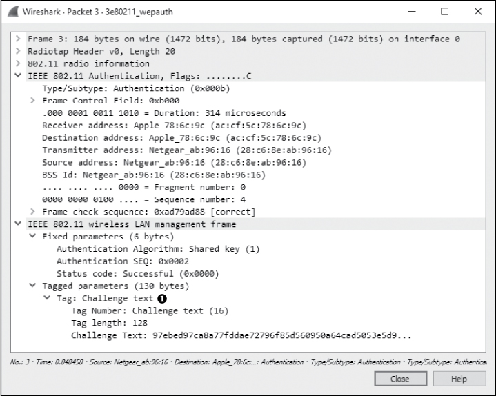
Figure 13-11: The WAP issues challenge text to the wireless client.

Figure 13-12: The wireless client sends the unencrypted challenge text back to the WAP.
The WAP responds to the wireless client in packet 5, as shown in Figure 13-13. The response contains a notification that the authentication process was successful ➊.
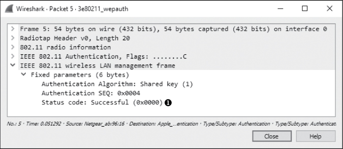
Figure 13-13: The WAP alerts the client that authentication was successful.
Finally, after successful authentication, the client can transmit an association request, receive an acknowledgment, and complete the connection process, as shown in Figure 13-14.
Figure 13-14: The authentication process is followed by a simple two-packet association request and response.
Failed WEP Authentication
3e80211_WEPauthfail.pcapng.
In our next example, a user enters a WEP key to connect to a WAP. After several seconds, the wireless client utility reports that it was unable to connect to the wireless network but fails to tell why. The resulting file is 3e80211_WEPauthfail.pcapng.
As with the successful attempt, this communication begins with the WAP’s sending challenge text to the wireless client in packet 3. In packet 4, the wireless client sends its response using the WEP key provided by the user.
At this point, we would expect to see a notification that the authentication was successful, but we see something different in packet 5, as shown in Figure 13-15 ➊.
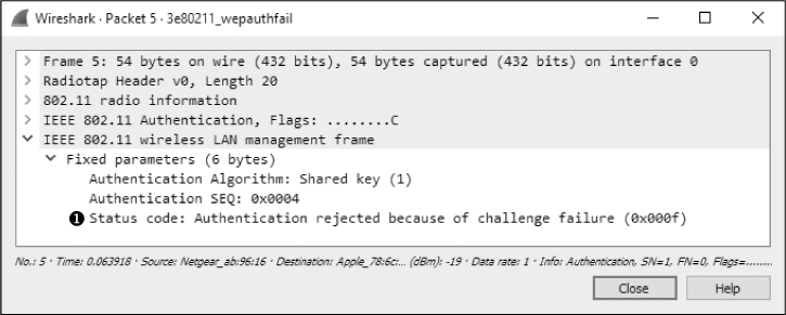
Figure 13-15: This message tells us the authentication was unsuccessful.
This message tells us that the wireless client’s response to the challenge text was incorrect and suggests that the WEP key the client used to decrypt the text must have also been incorrect. As a result, the connection process has failed. It must be reattempted with the proper WEP key.
Successful WPA Authentication
3e80211_WPAauth.pcapng
WPA uses a very different authentication mechanism than WEP, but it still relies on the user to enter a key into the wireless client to connect to the network. An example of a successful WPA authentication is found in the file 3e80211_WPAauth.pcapng.
The first packet in this file is a beacon broadcast from the WAP. Expand the 802.11 header of this packet, look under tagged parameters, and expand the Vendor Specific heading, as shown in Figure 13-16. You should see a section devoted to the WPA attributes of the WAP ➊. This lets us know the version and implementation of WPA that a WAP supports, if any.

Figure 13-16: This beacon lets us know that the WAP supports WPA authentication.
Once the beacon is received, the wireless client (ac:cf:5c:78:6c:9c) broadcasts a probe request in packet 2 that is received by the WAP (28:c6 :8e:ab:96:16), which responds in packet 3. After that, authentication and association requests and responses are generated between the wireless client and WAP in packets 4 through 7. These are similar to the authentication and association packets we saw in the WEP example earlier, but no challenge and response occur here. That exchange happens next.
Things really start to pick up in packet 8. This is where the WPA handshake begins, continuing through packet 11. During the handshake, the WPA challenge and response take place, as shown in Figure 13-17.

Figure 13-17: These packets are a part of the WPA handshake.
There are two challenges and responses. Each can be matched with the other based on the Replay Counter field under the 802.1x Authentication header, as shown in Figure 13-18. Notice that the Replay Counter value for the first two handshake packets is 1 ➊ and for the second two handshake packets is 2 ➋.

Figure 13-18: The Replay Counter field helps us pair challenges and responses.
After the WPA handshake is completed and authentication is successful, data begins transferring between the wireless client and the WAP.
NOTE
This example is from a WAP using WPA with TKIP encryption. TKIP is just one method for encrypting data on WLANs. There are many other types of encryption, and different access points will support different techniques. A WAP using a different encryption method or WPA version will likely exhibit different characteristics at the packet level. You can read the RFC document relating to the technology being used to better decipher what the connection sequence should look like.
Failed WPA Authentication
3e80211_WPAauthfail.pcapng
As with WEP, we’ll look at what happens when a user enters a WPA key and the wireless client utility reports that it was unable to connect to the wireless network without indicating the problem. The resulting file is 3e80211_WPAauthfail.pcapng.
The capture file begins in a manner identical to the file showing a successful WPA authentication and includes probe, authentication, and association requests. The WPA handshake begins in packet 8, but in this case, there are eight handshake packets instead of the four we saw in the successful authentication attempt.
Packets 8 and 9 represent the first two packets seen in the WPA handshake. In this case, however, the challenge text the client sends back to the WAP is incorrect. As a result, the sequence is repeated in packets 10 and 11, 12 and 13, and 14 and 15, as shown in Figure 13-19. Each request and response can be paired using the Replay Counter value.
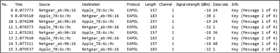
Figure 13-19: The additional EAPoL (Extensible Authentication Protocol over LAN) packets here indicate the failed WPA authentication.
Once the handshake process has been attempted and failed four times, the communication is aborted. As shown in Figure 13-20, the wireless client deauthenticates from the WAP in packet 16 ➊.
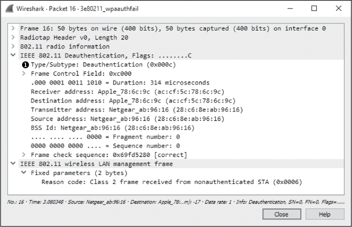
Figure 13-20: After failing the WPA handshake, the client deauthenticates.
Final Thoughts
Although wireless networks are still considered somewhat insecure, unless a plethora of additional security mechanisms are piled on, that concern hasn’t slowed their deployment in various organizational environments. As communication without wires is the new norm, it’s crucial to be able to capture and analyze data on wireless networks, as well as wired ones. The skills and concepts taught in this chapter are by no means exhaustive, but they should provide a jump-start for understanding the intricacies of troubleshooting wireless networks with packet analysis.