
Chapter 5
Shading Basics
“A good picture is equivalent to a good deed.”
—Vincent Van Gogh
When you render images of three-dimensional objects, the models should not only have the proper geometrical shape, they should also have the desired visual appearance. Depending on the application, this can range from photorealism—an appearance nearly identical to photographs of real objects—to various types of stylized appearance chosen for creative reasons. See Figure 5.1 for examples of both.
This chapter will discuss those aspects of shading that are equally applicable to photorealistic and stylized rendering. Chapter 15 is dedicated specifically to stylized rendering, and a significant part of the book, Chapters 9 through 14, focuses on physically based approaches commonly used for photorealistic rendering.
5.1 Shading Models
The first step in determining the appearance of a rendered object is to choose a shading model to describe how the object’s color should vary based on factors such as surface orientation, view direction, and lighting.
As an example, we will use a variation on the Gooch shading model [561]. This is a form of non-photorealistic rendering, the subject of Chapter 15. The Gooch shading model was designed to increase legibility of details in technical illustrations.
The basic idea behind Gooch shading is to compare the surface normal to the light’s location. If the normal points toward the light, a warmer tone is used to color the surface; if it points away, a cooler tone is used. Angles in between interpolate between these tones, which are based on a user-supplied surface color. In this example, we add a stylized “highlight” effect to the model to give the surface a shiny appearance. Figure 5.2 shows the shading model in action.
Shading models often have properties used to control appearance variation. Setting the values of these properties is the next step in determining object appearance. Our example model has just one property, surface color, as shown in the bottom image of Figure 5.2.

Figure 5.1. The top image is from a realistic landscape scene rendered using the Unreal Engine. The bottom image is from the game Firewatch
Like most shading models, this example is affected by the surface orientation relative to the view and lighting directions. For shading purposes, these directions are commonly expressed as normalized (unit-length) vectors, as illustrated in Figure 5.3.
Now that we have defined all the inputs to our shading model, we can look at the mathematical definition of the model itself:
(5.1)
cshaded=schighlight+(1-s)(tcwarm+(1-t)ccool).
Figure 5.2. A stylized shading model combining Gooch shading with a highlight effect. The top image shows a complex object with a neutral surface color. The bottom image shows spheres with various different surface colors. (Chinese Dragon mesh from Computer Graphics Archive [1172], original model from Stanford 3D Scanning Repository.)

Figure 5.3. Unit-length vector inputs to the example shading model (and most others): surface normal n , view vector v , and light direction l .figSPSUNDSCRgoochSPSUNDSCRvectors
In this equation, we have used the following intermediate calculations:
(5.2)
ccool=(0,0,0.55)+0.25csurface,cwarm=(0.3,0.3,0)+0.25csurface,chighlight=(1,1,1),t=(n·l)+12,r=2(n·l)n-l,s=(100(r·v)-97)+.Several of the mathematical expressions in this definition are often found in other shading models as well. Clamping operations, typically clamping to 0 or clamping between 0 and 1, are common in shading. Here we use the x+ notation, introduced in Section 1.2, for the clamp between 0 and 1 used in the computation of the highlight blend factor s. The dot product operator appears three times, in each case between two unit-length vectors; this is an extremely common pattern. The dot product of two vectors is the product of their lengths and the cosine of the angle between them. So, the dot product of two unit-length vectors is simply the cosine, which is a useful measure of the degree to which two vectors are aligned with each other. Simple functions composed of cosines are often the most pleasing and accurate mathematical expressions to account for the relationship between two directions, e.g., light direction and surface normal, in a shading model.
Another common shading operation is to interpolate linearly between two colors based on a scalar value between 0 and 1. This operation takes the form tca + (1-t)cb that interpolates between ca and cb as the value of t moves between 1 and 0, respectively. This pattern appears twice in this shading model, first to interpolate between cwarm and ccool and second to interpolate between the result of the previous interpolation and chighlight . Linear interpolation appears so often in shaders that it is a built-in function, called lerp or mix, in every shading language we have seen.
The line “ r=2(n·l)n-l ” computes the reflected light vector, reflecting l about n . While not quite as common as the previous two operations, this is common enough for most shading languages to have a built-in reflect function as well.
By combining such operations in different ways with various mathematical expressions and shading parameters, shading models can be defined for a huge variety of stylized and realistic appearances.
5.2 Light Sources
The impact of lighting on our example shading model was quite simple; it provided a dominant direction for shading. Of course, lighting in the real world can be quite complex. There can be multiple light sources each with its own size, shape, color, and intensity; indirect lighting adds even more variation. As we will see in Chapter 9, physically based, photorealistic shading models need to take all these parameters into account.
In contrast, stylized shading models may use lighting in many different ways, depending on the needs of the application and visual style. Some highly stylized models may have no concept of lighting at all, or (like our Gooch shading example) may only use it to provide some simple directionality.
The next step in lighting complexity is for the shading model to react to the presence or absence of light in a binary way. A surface shaded with such a model would have one appearance when lit and a different appearance when unaffected by light. This implies some criteria for distinguishing the two cases: distance from light sources, shadowing (which will be discussed in Chapter ), whether the surface is facing away from the light source (i.e., the angle between the surface normal n and the light vector l is greater than 90∘ ), or some combination of these factors.
It is a small step from the binary presence or absence of light to a continuous scale of light intensities. This could be expressed as a simple interpolation between absence and full presence, which implies a bounded range for the intensity, perhaps 0 to 1, or as an unbounded quantity that affects the shading in some other way. A common option for the latter is to factor the shading model into lit and unlit parts, with the light intensity klight linearly scaling the lit part:
(5.3)
cshaded=funlit(n,v)+klightflit(l,n,v).This easily extends to an RGB light color clight ,
(5.4)
cshaded=funlit(n,v)+clightflit(l,n,v),and to multiple light sources,
(5.5)
cshaded=funlit(n,v)+∑ni=1clightiflit(li,n,v).The unlit part funlit(n,v) corresponds to the “appearance when unaffected by light” of shading models that treat light as a binary. It can have various forms, depending on the desired visual style and the needs of the application. For example, funlit()=(0,0,0) will cause any surface unaffected by a light source to be colored pure black. Alternately, the unlit part could express some form of stylized appearance for unlit objects, similar to the Gooch model’s cool color for surfaces facing away from light. Often, this part of the shading model expresses some form of lighting that does not come directly from explicitly placed light sources, such as light from the sky or light bounced from surrounding objects. These other forms of lighting will be discussed in Chapters and 11.
We mentioned earlier that a light source does not affect a surface point if the light direction l is more than 90∘ from the surface normal n , in effect coming from underneath the surface. This can be thought of as a special case of a more general relationship between the light’s direction, relative to the surface, and its effect on shading. Although physically based, this relationship can be derived from simple geometrical principles and is useful for many types of non-physically based, stylized shading models as well.

Figure 5.4. The upper row of drawings shows a cross-section view of light on a surface. On the left the light rays hit the surface straight on, in the center they hit the surface at an angle, and on the right we see the use of vector dot products to compute the angle cosine. The bottom drawing shows the cross-section plane (which includes the light and view vectors) in relation to the full surface.
The effect of light on a surface can be visualized as a set of rays, with the density of rays hitting the surface corresponding to the light intensity for surface shading purposes. See Figure 5.4, which shows a cross section of a lit surface. The spacing between light rays hitting the surface along that cross section is inversely proportional to the cosine of the angle between l and n . So, the overall density of light rays hitting the surface is proportional to the cosine of the angle between l and n , which, as we have seen earlier, is equal to the dot product between those two unit-length vectors. Here we see why it is convenient to define the light vector l opposite to the light’s direction of travel; otherwise we would have to negate it before performing the dot product.
More precisely, the ray density (and thus the light’s contribution to shading) is proportional to the dot product when it is positive. Negative values correspond to light rays coming from behind the surface, which have no effect. So, before multiplying the light’s shading by the lighting dot product, we need to first clamp the dot product to 0. Using the x+ notation introduced in Section 1.2, which means clamping negative values to zero, we have
(5.6)
cshaded=funlit(n,v)+∑ni=1(li·n)+clightiflit(li,n,v).Shading models that support multiple light sources will typically use one of the structures from Equation 5.5, which is more general, or Equation 5.6, which is required for physically based models. It can be advantageous for stylized models as well, since it helps ensure an overall consistency to the lighting, especially for surfaces that are facing away from the light or are shadowed. However, some models are not a good fit for that structure; such models would use the structure in Equation 5.5.
The simplest possible choice for the function flit() is to make it a constant color,
(5.7)
flit()=csurface,which results in the following shading model:
(5.8)
cshaded=funlit(n,v)+∑ni=1(li·n)+clighticsurface.The lit part of this model corresponds to the Lambertian shading model, after Johann Heinrich Lambert [967], who published it in 1760! This model works in the context of ideal diffusely reflecting surfaces, i.e., surfaces that are perfectly matte. We present here a somewhat simplified explanation of Lambert’s model, which will be covered with more rigor in Chapter 9. The Lambertian model can be used by itself for simple shading, and it is a key building block in many shading models.
We can see from Equations 5.3–5.6 that a light source interacts with the shading model via two parameters: the vector l pointing toward the light and the light color clight . There are various different types of light sources, which differ primarily in how these two parameters vary over the scene.
We will next discuss several popular types of light sources, which have one thing in common: At a given surface location, each light source illuminates the surface from only one direction l . In other words, the light source, as seen from the shaded surface location, is an infinitesimally small point. This is not strictly true for real-world lights, but most light sources are small relative to their distance from illuminated surfaces, making this a reasonable approximation. In Sections 7.1.2 and 10.1, we will discuss light sources that illuminate a surface location from a range of directions, i.e., “area lights.”
5.2.1. Directional Lights
Directional light is the simplest model of a light source. Both l and clight are constant over the scene, except that clight may be attenuated by shadowing. Directional lights have no location. Of course, actual light sources do have specific locations in space. Directional lights are abstractions, which work well when the distance to the light is large relative to the scene size. For example, a floodlight 20 feet away illuminating a small tabletop diorama could be represented as a directional light. Another example is pretty much any scene lit by the sun, unless the scene in question is something such as the inner planets of the solar system.
The concept of a directional light can be somewhat extended to allow varying the value of clight while the light direction l remains constant. This is most often done to bound the effect of the light to a particular part of the scene for performance or creative reasons. For example, a region could be defined with two nested (one inside the other) box-shaped volumes, where clight is equal to (0, 0, 0) (pure black) outside the outer box, is equal to some constant value inside the inner box, and smoothly interpolates between those extremes in the region between the two boxes.
5.2.2. Punctual Lights
A punctual light is not one that is on time for its appointments, but rather a light that has a location, unlike directional lights. Such lights also have no dimensions to them, no shape or size, unlike real-world light sources. We use the term “punctual,” from the Latin punctus meaning “point,” for the class consisting of all sources of illumination that originate from a single, local position. We use the term “point light” to mean a specific kind of emitter, one that shines light equally in all directions. So, point and spotlight are two different forms of punctual lights. The light direction vector l varies depending on the location of the currently shaded surface point p0 relative to the punctual light’s position plight :
(5.9)
l=plight-p0||plight-p0||.This equation is an example of vector normalization: dividing a vector by its length to produce a unit-length vector pointing in the same direction. This is another common shading operation, and, like the shading operations we have seen in the previous section, it is a built-in function in most shading languages. However, sometimes an intermediate result from this operation is needed, which requires performing the normalization explicitly, in multiple steps, using more basic operations. Applying this to the punctual light direction computation gives us the following:
(5.10)
d=plight-p0,r=√d·d,l=dr.Since the dot product of two vectors is equal to the product of the two vector’s lengths with the cosine of the angle between them, and the cosine of 0∘ is 1.0, the dot product of a vector with itself is the square of its length. So, to find the length of any vector, we just dot it with itself and take the square root of the result.
The intermediate value that we need is r, the distance between the punctual light source and the currently shaded point. Besides its use in normalizing the light vector, the value of r is also needed to compute the attenuation (darkening) of the light color clight as a function of distance. This will be discussed further in the following section.
Point/Omni Lights
Punctual lights that emit light uniformly in all directions are known as point lights or omni lights. For point lights, clight varies as a function of the distance r, with the only source of variation being the distance attenuation mentioned above. Figure 5.5 shows why this darkening occurs, using similar geometric reasoning as the demonstration of the cosine factor in Figure 5.4. At a given surface, the spacing between rays from a point light is proportional to the distance from the surface to the light. Unlike the cosine factor in Figure 5.4, this spacing increase happens along both dimensions of the surface, so the ray density (and thus the light color clight ) is proportional to the inverse square distance 1/r2 . This enables us to specify the spatial variation in clight with a single light property, clight0 , which is defined as the value of clight at a fixed reference distance r0 :
(5.11)
clight(r)=clight0(r0r)2.Equation 5.11 is often referred to as inverse-square light attenuation. Although technically the correct distance attenuation for a point light, there are some issues that make this equation less than ideal for practical shading use.
The first issue occurs at relatively small distances. As the value of r tends to 0, the value of clight will increase in an unbounded manner. When r reaches 0, we will have a divide-by-zero singularity. To address this, one common modification is to add a small value ϵ to the denominator [861]:
(5.12)
clight(r)=clight0r20r2+ϵ.The exact value used for ϵ depends on the application; for example, the Unreal game engine uses ϵ=1cm [861].
An alternative modification, used in the CryEngine [1591] and Frostbite [960] game engines, is to clamp r to a minimum value rmin :
(5.13)
clight(r)=clight0(r0max(r,rmin))2.Unlike the somewhat arbitrary ϵ value used in the previous method, the value of rmin has a physical interpretation: the radius of the physical object emitting the light. Values of r smaller than rmin correspond to the shaded surface penetrating inside the physical light source, which is impossible.

Figure 5.5. The spacing between light rays from a point light increases proportionally to the distance r. Since the spacing increase occurs in two dimensions, the density of rays (and thus the light intensity) decreases proportionally to 1/r2 .
In contrast, the second issue with inverse-square attenuation occurs at relatively large distances. The problem is not with visuals but with performance. Although light intensity keeps decreasing with distance it never goes to 0. For efficient rendering, it is desirable for lights to reach 0 intensity at some finite distance (Chapter 20). There are many different ways in which the inverse-square equation could be modified to achieve this. Ideally the modification should introduce as little change as possible. To avoid a sharp cutoff at the boundary of the light’s influence, it is also preferable for the derivative and value of the modified function to reach 0 at the same distance. One solution is to multiply the inverse-square equation by a windowing function with the desired properties. One such function [860] is used by both the Unreal Engine [861] and Frostbite [960] game engines:
(5.14)
fwin(r)=(1-(rrmax)4)+2.The +2 means to clamp the value, if negative, to 0 before squaring it. Figure 5.6 shows an example inverse-square curve, the windowing function from Equation 5.14, and the result of multiplying the two.

Figure 5.6. This graph shows an inverse-square curve (using the ϵ method to avoid singularities, with an ϵ value of 1), the windowing function described in Equation 5.14 (with rmax set to 3), and the windowed curve.
Application requirements will affect the choice of method used. For example, having the derivative equal to 0 at rmax is particularly important when the distance attenuation function is sampled at a relatively low spatial frequency (e.g., in light maps or per-vertex). CryEngine does not use light maps or vertex lighting, so it employs a simpler adjustment, switching to linear falloff in the range between 0.8rmax and rmax [1591].
For some applications, matching the inverse-square curve is not a priority, so some other function entirely is used. This effectively generalizes Equations 5.11–5.14 to the following:
(5.15)
clight(r)=clight0fdist(r),where fdist(r) is some function of distance. Such functions are called distance falloff functions. In some cases, the use of non-inverse-square falloff functions is driven by performance constraints. For example, the game Just Cause 2 needed lights that were extremely inexpensive to compute. This dictated a falloff function that was simple to compute, while also being smooth enough to avoid per-vertex lighting artifacts [1379]:
(5.16)
fdist(r)=(1-(rrmax)2)+2.In other cases, the choice of falloff function may be driven by creative considerations. For example, the Unreal Engine, used for both realistic and stylized games, has two modes for light falloff: an inverse-square mode, as described in Equation 5.12, and an exponential falloff mode that can be tweaked to create a variety of attenuation curves [1802]. The developers of the game Tomb Raider used spline-editing tools to author falloff curves [953], allowing for even greater control over the curve shape.
Spotlights
Unlike point lights, illumination from nearly all real-world light sources varies by direction as well as distance. This variation can be expressed as a directional falloff function fdir(l) , which combines with the distance falloff function to define the overall spatial variation in light intensity:
(5.17)
clight=clight0fdist(r)fdir(l).Different choices of fdir(l) can produce various lighting effects. One important type of effect is the spotlight, which projects light in a circular cone. A spotlight’s directional falloff function has rotational symmetry around a spotlight direction vector s , and thus can be expressed as a function of the angle θs between s and the reversed light vector -l to the surface. The light vector needs to be reversed because we define l at the surface as pointing toward the light, and here we need the vector pointing away from the light.
Most spotlight functions use expressions composed of the cosine of θs , which (as we have seen earlier) is the most common form for angles in shading. Spotlights typically have an umbra angle θu , which bounds the light such that fdir(l)=0 for all θs≥θu . This angle can be used for culling in a similar manner to the maximum falloff distance rmax seen earlier. It is also common for spotlights to have a penumbra angle θp , which defines an inner cone where the light is at its full intensity. See Figure 5.7.

Figure 5.7. A spotlight: θs is the angle from the light’s defined direction s to the vector -l , the direction to the surface; θp shows the penumbra; and θu shows the umbra angles defined for the light.
Various directional falloff functions are used for spotlights, but they tend to be roughly similar. For example, the function fdirF(l) is used in the Frostbite game engine [960], and the function fdirT(l) is used in the three.js browser graphics library [218]:
(5.18)
t=(cosθs-cosθucosθp-cosθu)+,fdirF(l)=t2,fdirT(l)=smoothstep(t)=t2(3-2t).Recall that x+ is our notation for clamping x between 0 and 1, as introduced in Section 1.2. The smoothstep function is a cubic polynomial that is often used for smooth interpolation in shading. It is a built-in function in most shading languages.
Figure 5.8 shows some of the light types we have discussed so far.

Figure 5.8. Some types of lights. From left to right: directional, point light with no falloff, and spotlight with a smooth transition. Note that the point light dims toward the edges due to the changing angle between the light and the surface.
Other Punctual Lights
There are many other ways in which the clight value of a punctual light can vary.
The fdir(l) function is not limited to the simple spotlight falloff functions discussed above; it can represent any type of directional variation, including complex tabulated patterns measured from real-world light sources. The Illuminating Engineering Society (IES) have defined a standard file format for such measurements. IES profiles are available from many lighting manufacturers and have been used in the game Killzone: Shadow Fall [379,380], as well as the Unreal [861] and Frostbite [960] game engines, among others. Lagarde gives a good summary [961] of issues relating to parsing and using this file format.
The game Tomb Raider (2013) [953] has a type of punctual light that applies independent falloff functions for distance along the x, y, and z world axes. In Tomb Raider curves can also be applied to vary light intensity over time, e.g., to produce a flickering torch.
In Section 6.9 we will discuss how light intensity and color can be varied via the use of textures.
5.2.3. Other Light Types
Directional and punctual lights are primarily characterized by how the light direction l is computed. Different types of lights can be defined by using other methods to compute the light direction. For example, in addition to the light types mentioned earlier, Tomb Raider also has capsule lights that use a line segment as the source instead of a point [953]. For each shaded pixel, the direction to the closest point on the line segment is used as the light direction l .
As long as the shader has l and clight values for use in evaluating the shading equation, any method can be used to compute those values.
The types of light discussed so far are abstractions. In reality, light sources have size and shape, and they illuminate surface points from multiple directions. In rendering, such lights are called area lights, and their use in real-time applications is steadily increasing. Area-light rendering techniques fall into two categories: those that simulate the softening of shadow edges that results from the area light being partially occluded (Section 7.1.2) and those that simulate the effect of the area light on surface shading (Section 10.1). This second category of lighting is most noticeable for smooth, mirror-like surfaces, where the light’s shape and size can be clearly discerned in its reflection. Directional and punctual lights are unlikely to fall into disuse, though they are no longer as ubiquitous as in the past. Approximations accounting for a light’s area have been developed that are relatively inexpensive to implement, and so are seeing wider use. Increased GPU performance also allows for more elaborate techniques than in the past.
5.3 Implementing Shading Models
To be useful, these shading and lighting equations must of course be implemented in code. In this section we will go over some key considerations for designing and writing such implementations. We will also walk through a simple implementation example.
5.3.1. Frequency of Evaluation
When designing a shading implementation, the computations need to be divided according to their frequency of evaluation. First, determine whether the result of a given computation is always constant over an entire draw call. In this case, the computation can be performed by the application, typically on the CPU, though a GPU compute shader could be used for especially costly computations. The results are passed to the graphics API via uniform shader inputs.
Even within this category, there is a broad range of possible frequencies of evaluation, starting from “once ever.” The simplest such case would be a constant subexpression in the shading equation, but this could apply to any computation based on rarely changing factors such as the hardware configuration and installation options. Such shading computations might be resolved when the shader is compiled, in which case there is no need to even set a uniform shader input. Alternatively, the computation might be performed in an offline precomputation pass, at installation time, or when the application is loaded.
Another case is when the result of a shading computation changes over an application run, but so slowly that updating it every frame is not necessary. For example, lighting factors that depend on the time of day in a virtual game world. If the computation is costly, it may be worthwhile to amortize it over multiple frames.
Other cases include computations that are performed once per frame, such as concatenating the view and perspective matrices; or once per model, such as updating model lighting parameters that depend on location; or once per draw call, e.g., updating parameters for each material within a model. Grouping uniform shader inputs by frequency of evaluation is useful for application efficiency, and can also help GPU performance by minimizing constant updates [1165].
If the result of a shading computation changes within a draw call, it cannot be passed to the shader through a uniform shader input. Instead, it must be computed by one of the programmable shader stages described in Chapter 3 and, if needed, passed to other stages via varying shader inputs. In theory, shading computations can be performed on any of the programmable stages, each one corresponding to a different evaluation frequency:
- Vertex shader—Evaluation per pre-tessellation vertex.
- Hull shader—Evaluation per surface patch.
- Domain shader—Evaluation per post-tessellation vertex.
- Geometry shader—Evaluation per primitive.
- Pixel shader—Evaluation per pixel.

Figure 5.9. A comparison of per-pixel and per-vertex evaluations for the example shading model from Equation 5.19, shown on three models of varying vertex density. The left column shows the results of per-pixel evaluation, the middle column shows per-vertex evaluation, and the right column presents wireframe renderings of each model to show vertex density. (Chinese Dragon mesh from Computer Graphics Archive [1172], original model from Stanford 3D Scanning Repository.)
In practice most shading computations are performed per pixel. While these are typically implemented in the pixel shader, compute shader implementations are increasingly common; several examples will be discussed in Chapter 20. The other stages are primarily used for geometric operations such as transformation and deformation. To understand why this is the case, we will compare the results of per-vertex and per-pixel shading evaluations. In older texts, these are sometimes referred to as Gouraud shading [578] and Phong shading [1414], respectively, though those terms are not often used today. This comparison uses a shading model somewhat similar to the one in Equation 5.1, but modified to work with multiple light sources. The full model will be given a bit later, when we cover an example implementation in detail.
Figure 5.9 shows the results of per-pixel and per-vertex shading on models with a wide range of vertex densities. For the dragon, an extremely dense mesh, the difference between the two is small. But on the teapot, vertex shading evaluation causes visible errors such as angularly shaped highlights, and on the two-triangle plane the vertex-shaded version is clearly incorrect. The cause of these errors is that parts of the shading equation, the highlight in particular, have values that vary nonlinearly over the mesh surface. This makes them a poor fit for the vertex shader, the results of which are interpolated linearly over the triangle before being fed to the pixel shader.

Figure 5.10. On the left, we see that linear interpolation of unit normals across a surface results in interpolated vectors with lengths less than one. On the right, we see that linear interpolation of normals with significantly different lengths results in interpolated directions that are skewed toward the longer of the two normals.
In principle, it would be possible to compute only the specular highlight part of the shading model in the pixel shader, and calculate the rest in the vertex shader. This would likely not result in visual artifacts and in theory would save some computation. In practice, this kind of hybrid implementation is often not optimal. The linearly varying parts of the shading model tend to be the least computationally costly, and splitting up the shading computation in this way tends to add enough overhead, such as duplicated computations and additional varying inputs, to outweigh any benefit.
As we mentioned earlier, in most implementations the vertex shader is responsible for non-shading operations such as geometry transformation and deformation. The resulting geometric surface properties, transformed into the appropriate coordinate system, are written out by the vertex shader, linearly interpolated over the triangle, and passed into the pixel shader as varying shader inputs. These properties typically include the position of the surface, the surface normal, and optionally surface tangent vectors, if needed for normal mapping.
Note that even if the vertex shader always generates unit-length surface normals, interpolation can change their length. See the left side of Figure 5.10. For this reason the normals need to be renormalized (scaled to length 1) in the pixel shader. However, the length of the normals generated by the vertex shader still matters. If the normal length varies significantly between vertices, e.g., as a side effect of vertex blending, this will skew the interpolation. This can be seen in the right side of Figure 5.10. Due to these two effects, implementations often normalize interpolated vectors before and after interpolation, i.e., in both the vertex and pixel shaders.
Unlike the surface normals, vectors that point toward specific locations, such as the view vector and the light vector for punctual lights, are typically not interpolated. Instead, the interpolated surface position is used to compute these vectors in the pixel shader. Other than the normalization, which as we have seen needs to be performed in the pixel shader in any case, each of these vectors is computed with a vector subtraction, which is quick. If for some reason it is necessary to interpolate these vectors, do not normalize them beforehand. This will yield incorrect results, as shown in Figure 5.11.

Figure 5.11. Interpolation between two light vectors. On the left, normalizing them before interpolation causes the direction to be incorrect after interpolation. On the right, interpolating the non-normalized vectors yields correct results.
Earlier we mentioned that the vertex shader transforms the surface geometry into “the appropriate coordinate system.” The camera and light positions, passed to the pixel shader through uniform variables, are typically transformed by the application into the same coordinate system. This minimizes work done by the pixel shader to bring all the shading model vectors into the same coordinate space. But which coordinate system is the “appropriate” one? Possibilities include the global world space as well as the local coordinate system of the camera or, more rarely, that of the currently rendered model. The choice is typically made for the rendering system as a whole, based on systemic considerations such as performance, flexibility, and simplicity. For example, if rendered scenes are expected to include huge numbers of lights, world space might be chosen to avoid transforming the light positions. Alternately, camera space might be preferred, to better optimize pixel shader operations relating to the view vector and to possibly improve precision (Section 16.6).
Although most shader implementations, including the example implementation we are about to discuss, follow the general outline described above, there are certainly exceptions. For example, some applications choose the faceted appearance of per-primitive shading evaluation for stylistic reasons. This style is often referred to as flat shading. Two examples are shown in Figure 5.12.
In principle, flat shading could be performed in the geometry shader, but recent implementations typically use the vertex shader. This is done by associating each primitive’s properties with its first vertex and disabling vertex value interpolation. Disabling interpolation (which can be done for each vertex value separately) causes the value from the first vertex to be passed to all pixels in the primitive.
5.3.2. Implementation Example
We will now present an example shading model implementation. As mentioned earlier, the shading model we are implementing is similar to the extended Gooch model from Equation 5.1, but modified to work with multiple light sources. It is described by

Figure 5.12. Two games that use flat shading as a stylistic choice: Kentucky Route Zero
(5.19)
cshaded=12ccool+∑ni=1(li·n)+clighti(sichighlight+(1-si)cwarm),with the following intermediate calculations:
(5.20)
ccool=(0,0,0.55)+0.25csurface,cwarm=(0.3,0.3,0)+0.25csurface,chighlight=(2,2,2),ri=2(n·li)n-li,si=(100(ri·v)-97)+.This formulation fits the multi-light structure in Equation 5.6, repeated here for convenience:
The lit and unlit terms in this case are
(5.21)
funlit(n,v)=12ccool,flit(li,n,v)=sichighlight+(1-si)cwarm,with the cool color’s unlit contribution adjusted to make results look more like the original equation.
In most typical rendering applications, varying values for material properties such as csurface would be stored in vertex data or, more commonly, in textures (Chapter ). However, to keep this example implementation simple, we will assume that csurface is constant across the model.
This implementation will use the shader’s dynamic branching capabilities to loop over all light sources. While this straightforward approach can work well for reasonably simple scenes, it does not scale well to large and geometrically complex scenes with many light sources. Rendering techniques to efficiently handle large light counts will be covered in Chapter 20. Also, in the interest of simplicity, we will only support one type of light source: point lights. Although the implementation is quite simple, it follows the best practices covered earlier.
Shading models are not implemented in isolation, but in the context of a larger rendering framework. This example is implemented inside a simple WebGL 2 application, modified from the “Phong-shaded Cube” WebGL 2 sample by Tarek Sherif [1623], but the same principles apply to more complex frameworks as well.
We will be discussing some samples of GLSL shader code and JavaScript WebGL calls from the application. The intent is not to teach the specifics of the WebGL API but to show general implementation principles. We will go through the implementation in “inside out” order, starting with the pixel shader, then the vertex shader, and finally the application-side graphics API calls.
Before the shader code proper, the shader source includes definitions of the shader inputs and outputs. As discussed earlier in Section 3.3, using GLSL terminology, shader inputs fall into two categories. One is the set of uniform inputs, which have values set by the application and which remain constant over a draw call. The second type consists of varying inputs, which have values that can change between shader invocations (pixels or vertices). Here we see the definitions of the pixel shader’s varying inputs, which in GLSL are marked in, as well as its outputs:
![]()
This pixel shader has a single output, which is the final shaded color. The pixel shader inputs match the vertex shader outputs, which are interpolated over the triangle before being fed into the pixel shader. This pixel shader has two varying inputs: surface position and surface normal, both in the application’s world-space coordinate system. The number of uniform inputs is much larger, so for brevity we will only show the definitions of two, both related to light sources:

Since these are point lights, the definition for each one includes a position and a color. These are defined as vec4 instead of vec3 to conform to the restrictions of the GLSL std140 data layout standard. Although, as in this case, the std140 layout can lead to some wasted space, it simplifies the task of ensuring consistent data layout between CPU and GPU, which is why we use it in this sample. The array of Light structs is defined inside a named uniform block, which is a GLSL feature for binding a group of uniform variables to a buffer object for faster data transfer. The array length is defined to be equal to the maximum number of lights that the application allows in a single draw call. As we will see later, the application replaces the MAXLIGHTS string in the shader source with the correct value (10 in this case) before shader compilation. The uniform integer uLightCount is the actual number of active lights in the draw call.
Next, we will take a look at the pixel shader code:


We have a function definition for the lit term, which is called by the main() function. Overall, this is a straightforward GLSL implementation of Equations 5.20 and 5.21. Note that the values of funlit() and cwarm are passed in as uniform variables. Since these are constant over the entire draw call, the application can compute these values, saving some GPU cycles.
This pixel shader uses several built-in GLSL functions. The reflect() function reflects one vector, in this case the light vector, in the plane defined by a second vector, in this case the surface normal. Since we want both the light vector and reflected vector to point away from the surface, we need to negate the former before passing it into reflect(). The clamp() function has three inputs. Two of them define a range to which the third input is clamped. The special case of clamping to the range between 0 and 1 (which corresponds to the HLSL saturate() function) is quick, often effectively free, on most GPUs. This is why we use it here, although we only need to clamp the value to 0, as we know it will not exceed 1. The function mix() also has three inputs and linearly interpolates between two of them, the warm color and the highlight color in this case, based on the value of the third, a mixing parameter between 0 and 1. In HLSL this function is called lerp(), for “linear interpolation.” Finally, normalize() divides a vector by its length, scaling it to a length of 1.
Now let us look at the vertex shader. We will not show any of its uniform definitions since we already saw some example uniform definitions for the pixel shader, but the varying input and output definitions are worth examining:

Note that, as mentioned earlier, the vertex shader outputs match the pixel shader varying inputs. The inputs include directives that specify how the data are laid out in the vertex array. The vertex shader code comes next:

These are common operations for a vertex shader. The shader transforms the surface position and normal into world space and passes them to the pixel shader for use in shading. Finally, the surface position is transformed into clip space and passed into gl_Position, a special system-defined variable used by the rasterizer. The gl_Position variable is the one required output from any vertex shader.
Note that the normal vectors are not normalized in the vertex shader. They do not need to be normalized since they have a length of 1 in the original mesh data and this application does not perform any operations, such as vertex blending or nonuniform scaling, that could change their length unevenly. The model matrix could have a uniform scale factor, but that would change the length of all normals proportionally and thus not result in the problem shown on the right side of Figure 5.10.
The application uses the WebGL API for various rendering and shader setup. Each of the programmable shader stages are set up individually, and then they are all bound to a program object. Here is the pixel shader setup code:

Note the “fragment shader” references. This term is used by WebGL (and OpenGL, on which it is based). As noted earlier in this book, although “pixel shader” is less precise in some ways, it is the more common usage, which we follow in this book. This code is also where the MAXLIGHTS string is replaced with the appropriate numerical value. Most rendering frameworks perform similar pre-compilation shader manipulations.
There is more application-side code for setting uniforms, initializing vertex arrays, clearing, drawing, and so on, which you can view in the program [1623] and which are explained by numerous API guides. Our goal here is to give a sense of how shaders are treated as separate processors, with their own programming environment. We thus end our walkthrough at this point.
5.3.3. Material Systems
Rendering frameworks rarely implement just a single shader, as in our simple example. Typically, a dedicated system is needed to handle the variety of materials, shading models, and shaders used by the application.
As explained in earlier chapters, a shader is a program for one of the GPU’s programmable shader stages. As such, it is a low-level graphics API resource and not something with which artists would interact directly. In contrast, a material is an artist-facing encapsulation of the visual appearance of a surface. Materials sometimes also describe non-visual aspects, such as collision properties, which we will not discuss further because they are outside the scope of this book.
While materials are implemented via shaders, this is not a simple one-to-one correspondence. In different rendering situations, the same material may use different shaders. A shader can also be shared by multiple materials. The most common case is parameterized materials. In its simplest form, material parameterization requires two types of material entities: material templates and material instances. Each material template describes a class of materials and has a set of parameters that can be assigned numerical, color, or texture values depending on the parameter type. Each material instance corresponds to a material template plus a specific set of values for all of its parameters. Some rendering frameworks such as the Unreal Engine [1802] allow for a more complex, hierarchical structure, with material templates deriving from other templates at multiple levels.
Parameters may be resolved at runtime, by passing uniform inputs to the shader program, or at compile time, by substituting values before the shader is compiled. A common type of compile-time parameter is a boolean switch that controls the activation of a given material feature. This can be set by artists via a checkbox in the material user interface or procedurally by the material system, e.g., to reduce shader cost for distant objects where the visual effect of the feature is negligible.
While the material parameters may correspond one-to-one with the parameters of the shading model, this is not always the case. A material may fix the value of a given shading model parameter, such as the surface color, to a constant value. Alternately, a shading model parameter may be computed as the result of a complex series of operations taking multiple material parameters, as well as interpolated vertex or texture values, as inputs. In some cases, parameters such as surface position, surface orientation, and even time may also factor into the calculation. Shading based on surface position and orientation is especially common in terrain materials. For example, the height and surface normal can be used to control a snow effect, blending in a white surface color on high-altitude horizontal and almost-horizontal surfaces. Time-based shading is common in animated materials, such as a flickering neon sign.
One of the most important tasks of a material system is dividing various shader functions into separate elements and controlling how these are combined. There are many cases where this type of composition is useful, including the following:
- Composing surface shading with geometric processing, such as rigid transforms, vertex blending, morphing, tessellation, instancing, and clipping. These bits of functionality vary independently: Surface shading depends on the material, and geometry processing depends on the mesh. So, it is convenient to author them separately and have the material system compose them as needed.
- Composing surface shading with compositing operations such as pixel discard and blending. This is particularly relevant to mobile GPUs, where blending is typically performed in the pixel shader. It is often desirable to select these operations independently of the material used for surface shading.
- Composing the operations used to compute the shading model parameters with the computation of the shading model itself. This allows authoring the shading model implementation once and reusing it in combination with various different methods for computing the shading model parameters.
- Composing individually selectable material features with each other, the selection logic, and the rest of the shader. This enables writing the implementation of each feature separately.
- Composing the shading model and computation of its parameters with light source evaluation: computing the values of clight and l at the shaded point for each light source. Techniques such as deferred rendering (discussed in Chapter 20) change the structure of this composition. In rendering frameworks that support multiple such techniques, this adds an additional layer of complexity.
It would be convenient if the graphics API provided this type of shader code modularity as a core feature. Sadly, unlike CPU code, GPU shaders do not allow for post-compilation linking of code fragments. The program for each shader stage is compiled as a unit. The separation between shader stages does offer some limited modularity, which somewhat fits the first item on our list: composing surface shading (typically performed in the pixel shader) with geometric processing (typically performed in other shader stages). But the fit is not perfect, since each shader performs other operations as well, and the other types of composition still need to be handled. Given these limitations, the only way that the material system can implement all these types of composition is at the source-code level. This primarily involves string operations such as concatenation and replacement, often performed via C-style preprocessing directives such as #include, #if, and #define.
Early rendering systems had a relatively small number of shader variants, and often each one was written manually. This has some benefits. For example, each variant can be optimized with full knowledge of the final shader program. However, this approach quickly becomes impractical as the number of variants grows. When taking all the different parts and options into account, the number of possible different shader variants is huge. This is why modularity and composability are so crucial.
The first question to be resolved when designing a system for handling shader variants is whether selection between different options is performed at runtime via dynamic branching, or at compile time via conditional preprocessing. On older hardware, dynamic branching was often impossible or extremely slow, so runtime selection was not an option. Variants were then all handled at compile time, including all possible combinations of counts of the different light types [1193].
In contrast, current GPUs handle dynamic branching quite well, especially when the branch behaves the same for all pixels in a draw call. Today much of the functionality variation, such as the number of lights, is handled at runtime. However, adding a large amount of functional variation to a shader incurs a different cost: an increase in register count and a corresponding reduction in occupancy, and thus performance. See Section 18.4.5 for more details. So, compile-time variation is still valuable. It avoids including complex logic that will never be executed.
As an example, let us imagine an application that supports three different types of lights. Two light types are simple: point and directional. The third type is a generalized spotlight that supports tabulated illumination patterns and other complex features, requiring a significant amount of shader code to implement. However, say the generalized spotlight is used relatively rarely, with less than 5% of the lights in the application being this type. In the past, a separate shader variant would be compiled for each possible combination of counts of the three light types, to avoid dynamic branching. While this would not be needed today, it may still be beneficial to compile two separate variants, one for the case when the count of generalized spotlights is equal to or greater than 1, and one for the case where the count of such lights is exactly 0. Due to its simpler code, the second variant (which is most commonly used) is likely to have lower register occupancy and thus higher performance.
Modern material systems employ both runtime and compile-time shader variation. Even though the full burden is no longer handled only at compile time, the overall complexity and number of variations keep increasing, so a large number of shader variants still need to be compiled. For example, in some areas of the game Destiny: The Taken King, over 9000 compiled shader variations were used in a single frame [1750]. The number of possible variations can be much larger, e.g., the Unity rendering system has shaders with close to 100 billion possible variants. Only the variants that are actually used are compiled, but the shader compilation system had to be redesigned to handle the huge number of possible variants [1439].
Material-system designers employ different strategies to address these design goals. Although these are sometimes presented as mutually exclusive system architectures [342], these strategies can be—and usually are—combined in the same system. These strategies include the following:
- Code reuse—Implementing functions in shared files, using #include preprocessor directives to access those functions from any shader that needs them.
- Subtractive—A shader, often referred to as an übershader or supershader [1170,1784], that aggregates a large set of functionality, using a combination of compile-time preprocessor conditionals and dynamic branching to remove unused parts and to switch between mutually exclusive alternatives.
- Additive—Various bits of functionality are defined as nodes with input and output connectors, and these are composed together. This is similar to the code reuse strategy but is more structured. The composition of nodes can be done via text [342] or a visual graph editor. The latter is intended to make it easier for non-engineers, such as technical artists, to author new material templates [1750,1802]. Typically only part of the shader is accessible to visual graph authoring. For example, in the Unreal Engine the graph editor can only affect the computation of shading model inputs [1802]. See Figure 5.13.
- Template-based—An interface is defined, into which different implementations can be plugged as long as they conform to that interface. This is a bit more formal than the additive strategy and is typically used for larger chunks of functionality. A common example for such an interface is the separation between the calculation of shading model parameters and the computation of the shading model itself. The Unreal Engine [1802] has different “material domains,” including the Surface domain for computing shading model parameters and the Light Function domain for computing a scalar value that modulates clight for a given light source. A similar “surface shader” structure also exists in Unity [1437]. Note that deferred shading techniques (discussed in Chapter 20) enforce a similar structure, with the G-buffer serving as the interface.

Figure 5.13. The Unreal Engine material editor. Note the tall node on the right side of the node graph. The input connectors of this node correspond to various shading inputs used by the rendering engine, including all the shading model parameters. (Material sample courtesy of Epic Games.)
For more specific examples, several chapters in the (now free) book WebGL Insights [301] discuss how a variety of engines control their shader pipelines. Besides composition, there are several other important design considerations for modern material systems, such as the need to support multiple platforms with minimal duplication of shader code. This includes variations in functionality to account for performance and capability differences among platforms, shading languages, and APIs. The Destiny shader system [1750] is a representative solution to this type of problem. It uses a proprietary preprocessor layer that takes shaders written in a custom shading language dialect. This allows writing platform-independent materials with automatic translation to different shading languages and implementations. The Unreal Engine [1802] and Unity [1436] have similar systems.
The material system also needs to ensure good performance. Besides specialized compilation of shading variants, there are a few other common optimizations the material system can perform. The Destiny shader system and the Unreal Engine automatically detect computations that are constant across a draw call (such as the warm and cool color computation in the earlier implementation example) and move it outside of the shader. Another example is the scoping system used in Destiny to differentiate between constants that are updated at different frequencies (e.g., once per frame, once per light, once per object) and update each set of constants at the appropriate times to reduce API overhead.
As we have seen, implementing a shading equation is a matter of deciding what parts can be simplified, how frequently to compute various expressions, and how the user is able to modify and control the appearance. The ultimate output of the rendering pipeline is a color and blend value. The remaining sections on antialiasing, transparency, and image display detail how these values are combined and modified for display.
5.4 Aliasing and Antialiasing
Imagine a large black triangle moving slowly across a white background. As a screen grid cell is covered by the triangle, the pixel value representing this cell should smoothly drop in intensity. What typically happens in basic renderers of all sorts is that the moment the grid cell’s center is covered, the pixel color immediately goes from white to black. Standard GPU rendering is no exception. See the leftmost column of Figure 5.14.

Figure 5.14. The upper row shows three images with different levels of antialiasing of a triangle, a line, and some points. The lower row images are magnifications of the upper row. The leftmost column uses only one sample per pixel, which means that no antialiasing is used. The middle column images were rendered with four samples per pixel (in a grid pattern), and the right column used eight samples per pixel (in a 4×4 checkerboard, half the squares sampled).
Triangles show up in pixels as either there or not there. Lines drawn have a similar problem. The edges have a jagged look because of this, and so this visual artifact is called “the jaggies,” which turn into “the crawlies” when animated. More formally, this problem is called aliasing, and efforts to avoid it are called antialiasing techniques.
The subject of sampling theory and digital filtering is large enough to fill its own book [559,1447,1729]. As this is a key area of rendering, the basic theory of sampling and filtering will be presented. We will then focus on what currently can be done in real time to alleviate aliasing artifacts.
5.4.1. Sampling and Filtering Theory
The process of rendering images is inherently a sampling task. This is so since the generation of an image is the process of sampling a three-dimensional scene in order to obtain color values for each pixel in the image (an array of discrete pixels). To use texture mapping (Chapter 6), texels have to be resampled to get good results under varying conditions. To generate a sequence of images in an animation, the animation is often sampled at uniform time intervals. This section is an introduction to the topic of sampling, reconstruction, and filtering. For simplicity, most material will be presented in one dimension. These concepts extend naturally to two dimensions as well, and can thus be used when handling two-dimensional images.
Figure 5.15 shows how a continuous signal is being sampled at uniformly spaced intervals, that is, discretized. The goal of this sampling process is

Figure 5.15. A continuous signal (left) is sampled (middle), and then the original signal is recovered by reconstruction (right).

Figure 5.16. The top row shows a spinning wheel (original signal). This is inadequately sampled in second row, making it appear to move in the opposite direction. This is an example of aliasing due to a too low sampling rate. In the third row, the sampling rate is exactly two samples per revolution, and we cannot determine in which direction the wheel is spinning. This is the Nyquist limit. In the fourth row, the sampling rate is higher than two samples per revolution, and we suddenly can see that the wheel spins in the right direction.
to represent information digitally. In doing so, the amount of information is reduced. However, the sampled signal needs to be reconstructed to recover the original signal. This is done by filtering the sampled signal.
Whenever sampling is done, aliasing may occur. This is an unwanted artifact, and we need to battle aliasing to generate pleasing images. A classic example of aliasing seen in old Westerns is a spinning wagon wheel filmed by a movie camera. Because the spokes move much faster than the camera records images, the wheel may appear to be spinning slowly (backward or forward), or may even look like it is not rotating at all. This can be seen in Figure 5.16. The effect occurs because the images of the wheel are taken in a series of time steps, and is called temporal aliasing.
Common examples of aliasing in computer graphics are the “jaggies” of a rasterized line or triangle edge, flickering highlights known as “fireflies”, and when a texture with a checker pattern is minified (Section 6.2.2).
Aliasing occurs when a signal is being sampled at too low a frequency. The sampled signal then appears to be a signal of lower frequency than the original. This is illustrated in Figure 5.17.

Figure 5.17. The solid blue line is the original signal, the red circles indicate uniformly spaced sample points, and the green dashed line is the reconstructed signal. The top figure shows a too low sample rate. Therefore, the reconstructed signal appears to be of lower frequency, i.e., an alias of the original signal. The bottom shows a sampling rate of exactly twice the frequency of the original signal, and the reconstructed signal is here a horizontal line. It can be proven that if the sampling rate is increased ever so slightly, perfect reconstruction is possible.
For a signal to be sampled properly (i.e., so that it is possible to reconstruct the original signal from the samples), the sampling frequency has to be more than twice the maximum frequency of the signal to be sampled. This is often called the sampling theorem, and the sampling frequency is called the Nyquist rate [1447] or Nyquist limit, after Harry Nyquist (1889–1976), a Swedish scientist who discovered this in 1928. The Nyquist limit is also illustrated in Figure 5.16. The fact that the theorem uses the term “maximum frequency” implies that the signal has to be band-limited, which just means that there are not any frequencies above a certain limit. Put another way, the signal has to be smooth enough relative to the spacing between neighboring samples.
A three-dimensional scene is normally never band-limited when rendered with point samples. Edges of triangles, shadow boundaries, and other phenomena produce a signal that changes discontinuously and so produces frequencies that are infinite [252]. Also, no matter how closely packed the samples are, objects can still be small enough that they do not get sampled at all. Thus, it is impossible to entirely avoid aliasing problems when using point samples to render a scene, and we almost always use point sampling. However, at times it is possible to know when a signal is band-limited. One example is when a texture is applied to a surface. It is possible to compute the frequency of the texture samples compared to the sampling rate of the pixel. If this frequency is lower than the Nyquist limit, then no special action is needed to properly sample the texture. If the frequency is too high, then a variety of algorithms are used to band-limit the texture (Section ).

Figure 5.18. The top left shows the box filter, and the top right the tent filter. The bottom shows the sinc filter (which has been clamped on the x-axis here).
Reconstruction
Given a band-limited sampled signal, we will now discuss how the original signal can be reconstructed from the sampled signal. To do this, a filter must be used. Three commonly used filters are shown in Figure 5.18. Note that the area of the filter should always be one, otherwise the reconstructed signal can appear to grow or shrink.
In Figure 5.19, the box filter (nearest neighbor) is used to reconstruct a sampled signal.

Figure 5.19. The sampled signal (left) is reconstructed using the box filter. This is done by placing the box filter over each sample point, and scaling it in the y-direction so that the height of the filter is the same as the sample point. The sum is the reconstruction signal (right).
This is the worst filter to use, as the resulting signal is a noncontinuous stair case. Still, it is often used in computer graphics because of its simplicity. As can be seen in the illustration, the box filter is placed over each sample point, and then scaled so that the topmost point of the filter coincides with the sample point. The sum of all these scaled and translated box functions is the reconstructed signal shown to the right.
The box filter can be replaced with any other filter. In Figure 5.20, the tent filter, also called the triangle filter, is used to reconstruct a sampled signal.

Figure 5.20. The sampled signal (left) is reconstructed using the tent filter. The reconstructed signal is shown to the right.
Note that this filter implements linear interpolation between neighboring sample points, and so it is better than the box filter, as the reconstructed signal now is continuous.
However, the smoothness of the reconstructed signal using a tent filter is poor; there are sudden slope changes at the sample points. This has to do with the fact that the tent filter is not a perfect reconstruction filter. To get perfect reconstruction the ideal low-pass filter has to be used. A frequency component of a signal is a sine wave: sin(2πf) , where f is the frequency of that component. Given this, a low-pass filter removes all frequency components with frequencies higher than a certain frequency defined by the filter. Intuitively, the low-pass filter removes sharp features of the signal, i.e., the filter blurs it. The ideal low-pass filter is the sinc filter (Figure 5.18 bottom):
(5.22)
sinc(x)=sin(πx)πx.The theory of Fourier analysis [1447] explains why the sinc filter is the ideal low-pass filter. Briefly, the reasoning is as follows. The ideal low-pass filter is a box filter in the frequency domain, which removes all frequencies above the filter width when it is multiplied with the signal. Transforming the box filter from the frequency domain to the spatial domain gives a sinc function. At the same time, the multiplication operation is transformed into the convolution function, which is what we have been using in this section, without actually describing the term.

Figure 5.21. Here, the sinc filter is used to reconstruct the signal. The sinc filter is the ideal low-pass filter.
Using the sinc filter to reconstruct the signal gives a smoother result, as shown in Figure 5.21. The sampling process introduces high-frequency components (abrupt changes) in the signal, and the task of the low-pass filter is to remove these. In fact, the sinc filter eliminates all sine waves with frequencies higher than 1 / 2 the sampling rate. The sinc function, as presented in Equation 5.22, is the perfect reconstruction filter when the sampling frequency is 1.0 (i.e., the maximum frequency of the sampled signal must be smaller than 1 / 2). More generally, assume the sampling frequency is fs , that is, the interval between neighboring samples is 1/fs . For such a case, the perfect reconstruction filter is sinc(fsx) , and it eliminates all frequencies higher than fs/2 . This is useful when resampling the signal (next section). However, the filter width of the sinc is infinite and is negative in some areas, so it is rarely useful in practice.
There is a useful middle ground between the low-quality box and tent filters on one hand, and the impractical sinc filter on the other. Most widely used filter functions [1214,1289,1413,1793] are between these extremes. All these filter functions have some approximation to the sinc function, but with a limit on how many pixels they influence. The filters that most closely approximate the sinc function have negative values over part of their domain. For applications where negative filter values are undesirable or impractical, filters with no negative lobes (often referred to generically as Gaussian filters, since they either derive from or resemble a Gaussian curve) are typically used [1402]. Section 12.1 discusses filter functions and their use in more detail.
After using any filter, a continuous signal is obtained. However, in computer graphics we cannot display continuous signals directly, but we can use them to resample the continuous signal to another size, i.e., either enlarging the signal, or diminishing it. This topic is discussed next.
Resampling
Resampling is used to magnify or minify a sampled signal. Assume that the original sample points are located at integer coordinates ( 0,1,2,⋯) , that is, with unit intervals between samples. Furthermore, assume that after resampling we want the new sample points to be located uniformly with an interval a between samples. For a>1 , minification (downsampling) takes place, and for a<1 , magnification (upsampling) occurs.
Magnification is the simpler case of the two, so let us start with that. Assume the sampled signal is reconstructed as shown in the previous section. Intuitively, since the signal now is perfectly reconstructed and continuous, all that is needed is to resample the reconstructed signal at the desired intervals. This process can be seen in Figure 5.22.

Figure 5.22. On the left is the sampled signal, and the reconstructed signal. On the right, the reconstructed signal has been resampled at double the sample rate, that is, magnification has taken place.
However, this technique does not work when minification occurs. The frequency of the original signal is too high for the sampling rate to avoid aliasing. Instead it has been shown that a filter using sinc(x/a) should be used to create a continuous signal from the sampled one [1447,1661]. After that, resampling at the desired intervals can take place. This can be seen in Figure 5.23.

Figure 5.23. On the left is the sampled signal, and the reconstructed signal. On the right, the filter width has doubled in order to double the interval between the samples, that is, minification has taken place.
Said another way, by using sinc(x/a) as a filter here, the width of the low-pass filter is increased, so that more of the signal’s higher frequency content is removed. As shown in the figure, the filter width (of the individual sinc ’s) is doubled to decrease the resampling rate to half the original sampling rate. Relating this to a digital image, this is similar to first blurring it (to remove high frequencies) and then resampling the image at a lower resolution.
With the theory of sampling and filtering available as a framework, the various algorithms used in real-time rendering to reduce aliasing are now discussed.
5.4.2. Screen-Based Antialiasing
Edges of triangles produce noticeable artifacts if not sampled and filtered well. Shadow boundaries, specular highlights, and other phenomena where the color is changing rapidly can cause similar problems. The algorithms discussed in this section help improve the rendering quality for these cases. They have the common thread that they are screen based, i.e., that they operate only on the output samples of the pipeline. There is no one best antialiasing technique, as each has different advantages in terms of quality, ability to capture sharp details or other phenomena, appearance during movement, memory cost, GPU requirements, and speed.
In the black triangle example in Figure 5.14, one problem is the low sampling rate. A single sample is taken at the center of each pixel’s grid cell, so the most that is known about the cell is whether or not the center is covered by the triangle. By using more samples per screen grid cell and blending these in some fashion, a better pixel color can be computed. This is illustrated in Figure 5.24.

Figure 5.24. On the left, a red triangle is rendered with one sample at the center of the pixel. Since the triangle does not cover the sample, the pixel will be white, even though a substantial part of the pixel is covered by the red triangle. On the right, four samples are used per pixel, and as can be seen, two of these are covered by the red triangle, which results in a pink pixel color.
The general strategy of screen-based antialiasing schemes is to use a sampling pattern for the screen and then weight and sum the samples to produce a pixel color, p :
(5.23)
p(x,y)=∑ni=1wic(i,x,y),where n is the number of samples taken for a pixel. The function c(i,x,y) is a sample color and wi is a weight, in the range [0, 1], that the sample will contribute to the overall pixel color. The sample position is taken based on which sample it is in the series 1,…,n , and the function optionally also uses the integer part of the pixel location (x, y). In other words, where the sample is taken on the screen grid is different for each sample, and optionally the sampling pattern can vary from pixel to pixel. Samples are normally point samples in real-time rendering systems (and most other rendering systems, for that matter). So, the function c can be thought of as two functions. First, a function f(i,n) retrieves the floating point (xf,yf) location on the screen where a sample is needed. This location on the screen is then sampled, i.e., the color at that precise point is retrieved. The sampling scheme is chosen and the rendering pipeline configured to compute the samples at particular subpixel locations, typically based on a per-frame (or per-application) setting.
The other variable in antialiasing is wi , the weight of each sample. These weights sum to one. Most methods used in real-time rendering systems give a uniform weight to their samples, i.e., wi=1n . The default mode for graphics hardware, a single sample at the center of the pixel, is the simplest case of the antialiasing equation above. There is only one term, the weight of this term is one, and the sampling function f always returns the center of the pixel being sampled.
Antialiasing algorithms that compute more than one full sample per pixel are called supersampling (or oversampling) methods. Conceptually simplest, full-scene antialiasing (FSAA), also known as “supersampling antialiasing” (SSAA), renders the scene at a higher resolution and then filters neighboring samples to create an image. For example, say an image of 1280×1024 pixels is desired. If you render an image of 2560×2048 offscreen and then average each 2×2 pixel area on the screen, the desired image is generated with four samples per pixel, filtered using a box filter. Note that this corresponds to 2×2 grid sampling in Figure 5.25. This method is costly, as all subsamples must be fully shaded and filled, with a z-buffer depth per sample. FSAA’s main advantage is simplicity. Other, lower-quality versions of this method sample at twice the rate on only one screen axis, and so are called 1×2 or 2×1 supersampling. Typically, powers-of-two resolution and a box filter are used for simplicity. NVIDIA’s dynamic super resolution feature is a more elaborate form of supersampling, where the scene is rendered at some higher resolution and a 13-sample Gaussian filter is used to generate the displayed image [1848].

Figure 5.25. A comparison of some pixel sampling schemes, ranging from least to most samples per pixel. Quincunx shares the corner samples and weights its center sample to be worth half of the pixel’s final color. The 2×2 rotated grid captures more gray levels for the nearly horizontal edge than a straight 2×2 grid. Similarly, the 8 rooks pattern captures more gray levels for such lines than a 4×4 grid, despite using fewer samples.
A sampling method related to supersampling is based on the idea of the accumulation buffer [637,1115]. Instead of one large offscreen buffer, this method uses a buffer that has the same resolution as the desired image, but with more bits of color per channel. To obtain a 2×2 sampling of a scene, four images are generated, with the view moved half a pixel in the screen x- or y-direction as needed. Each image generated is based on a different sample position within the grid cell. The additional costs of having to re-render the scene a few times per frame and copy the result to the screen makes this algorithm costly for real-time rendering systems. It is useful for generating higher-quality images when performance is not critical, since any number of samples, placed anywhere, can be used per pixel [1679]. The accumulation buffer used to be a separate piece of hardware. It was supported directly in the OpenGL API, but was deprecated in version 3.0. On modern GPUs the accumulation buffer concept can be implemented in a pixel shader by using a higher-precision color format for the output buffer.
Additional samples are needed when phenomena such as object edges, specular highlights, and sharp shadows cause abrupt color changes. Shadows can often be made softer and highlights smoother to avoid aliasing. Particular object types can be increased in size, such as electrical wires, so that they are guaranteed to cover at least one pixel at each location along their length [1384]. Aliasing of object edges still remains as a major sampling problem. It is possible to use analytical methods, where object edges are detected during rendering and their influence is factored in, but these are often more expensive and less robust than simply taking more samples. However, GPU features such as conservative rasterization and rasterizer order views have opened up new possibilities [327].
Techniques such as supersampling and accumulation buffering work by generating samples that are fully specified with individually computed shades and depths. The overall gains are relatively low and the cost is high, as each sample has to run through a pixel shader.
Multisampling antialiasing (MSAA) lessens the high computational costs by computing the surface’s shade once per pixel and sharing this result among the samples. Pixels may have, say, four (x, y) sample locations per fragment, each with their own color and z-depth, but the pixel shader is evaluated only once for each object fragment applied to the pixel. If all MSAA positional samples are covered by the fragment, the shading sample is evaluated at the center of the pixel. If instead the fragment covers fewer positional samples, the shading sample’s position can be shifted to better represent the positions covered. Doing so avoids shade sampling off the edge of a texture, for example. This position adjustment is called centroid sampling or centroid interpolation and is done automatically by the GPU, if enabled. Centroid sampling avoids off-triangle problems but can cause derivative computations to return incorrect values [530,1041]. See Figure 5.26.

Figure 5.26. In the middle, a pixel with two objects overlapping it. The red object covers three samples, the blue just one. Pixel shader evaluation locations are shown in green. Since the red triangle covers the center of the pixel, this location is used for shader evaluation. The pixel shader for the blue object is evaluated at the sample’s location. For MSAA, a separate color and depth is stored at all four locations. On the right the 2f4x mode for EQAA is shown. The four samples now have four ID values, which index a table of the two colors and depths stored.
MSAA is faster than a pure supersampling scheme because the fragment is shaded only once. It focuses effort on sampling the fragment’s pixel coverage at a higher rate and sharing the computed shade. It is possible to save more memory by further decoupling sampling and coverage, which in turn can make antialiasing faster still—the less memory touched, the quicker the render. NVIDIA introduced coverage sampling antialiasing (CSAA) in 2006, and AMD followed suit with enhanced quality antialiasing (EQAA). These techniques work by storing only the coverage for the fragment at a higher sampling rate. For example, EQAA’s “2f4x” mode stores two color and depth values, shared among four sample locations. The colors and depths are no longer stored for particular locations but rather saved in a table. Each of the four samples then needs just one bit to specify which of the two stored values is associated with its location. See Figure 5.26. The coverage samples specify the contribution of each fragment to the final pixel color. If the number of colors stored is exceeded, a stored color is evicted and its samples are marked as unknown. These samples do not contribute to the final color [382,383]. For most scenes there are relatively few pixels containing three or more visible opaque fragments that are radically different in shade, so this scheme performs well in practice [1405]. However, for highest quality, the game Forza Horizon 2 went with 4 × MSAA, though EQAA had a performance benefit [1002].
Once all geometry has been rendered to a multiple-sample buffer, a resolve operation is then performed. This procedure averages the sample colors together to determine the color for the pixel. It is worth noting that a problem can arise when using multisampling with high dynamic range color values. In such cases, to avoid artifacts you normally need to tone-map the values before the resolve [1375]. This can be expensive, so a simpler approximation to the tone map function or other methods can be used [862,1405].
By default, MSAA is resolved with a box filter. In 2007 ATI introduced custom filter antialiasing (CFAA) [1625], with the capabilities of using narrow and wide tent filters that extend slightly into other pixel cells. This mode has since been supplanted by EQAA support. On modern GPUs pixel or compute shaders can access the MSAA samples and use whatever reconstruction filter is desired, including one that samples from the surrounding pixels’ samples. A wider filter can reduce aliasing, though at the loss of sharp details. Pettineo [1402,1405] found that the cubic smoothstep and B-spline filters with a filter width of 2 or 3 pixels gave the best results overall. There is also a performance cost, as even emulating the default box filter resolve will take longer with a custom shader, and a wider filter kernel means increased sample access costs.
NVIDIA’s built-in TXAA support similarly uses a better reconstruction filter over a wider area than a single pixel to give a better result. It and the newer MFAA (multi-frame antialiasing) scheme both also use temporal antialiasing (TAA), a general class of techniques that use results from previous frames to improve the image. In part such techniques are made possible due to functionality that lets the programmer set the MSAA sampling pattern per frame [1406]. Such techniques can attack aliasing problems such as the spinning wagon wheel and can also improve edge rendering quality.
Imagine performing a sampling pattern “manually” by generating a series of images where each render uses a different location within the pixel for where the sample is taken. This offsetting is done by appending a tiny translation on to the projection matrix [1938]. The more images that are generated and averaged together, the better the result. This concept of using multiple offset images is used in temporal antialiasing algorithms. A single image is generated, possibly with MSAA or another method, and the previous images are blended in. Usually just two to four frames are used [382,836,1405]. Older images may be given exponentially less weight [862], though this can have the effect of the frame shimmering if the viewer and scene do not move, so often equal weighting of just the last and current frame is done. With each frame’s samples in a different subpixel location, the weighted sum of these samples gives a better coverage estimate of the edge than a single frame does. So, a system using the latest two frames averaged together can give a better result. No additional samples are needed for each frame, which is what makes this type of approach so appealing. It is even possible to use temporal sampling to allow generation of a lower-resolution image that is upscaled to the display’s resolution [1110]. In addition, illumination methods or other techniques that require many samples for a good result can instead use fewer samples each frame, since the results will be blended over several frames [1938].
While providing antialiasing for static scenes at no additional sampling cost, this type of algorithm has a few problems when used for temporal antialiasing. If the frames are not weighted equally, objects in a static scene can exhibit a shimmer. Rapidly moving objects or quick camera moves can cause ghosting, i.e., trails left behind the object due to the contributions of previous frames. One solution to ghosting is to perform such antialiasing on only slow-moving objects [1110]. Another important approach is to use reprojection (Section ) to better correlate the previous and current frames’ objects. In such schemes, objects generate motion vectors that are stored in a separate “velocity buffer” (Section ). These vectors are used to correlate the previous frame with the current one, i.e., the vector is subtracted from the current pixel location to find the previous frame’s color pixel for that object’s surface location. Samples unlikely to be part of the surface in the current frame are discarded [1912]. Because no extra samples, and so relatively little extra work, are needed for temporal antialiasing, there has been a strong interest and wider adoption of this type of algorithm in recent years. Some of this attention has been because deferred shading techniques (Section ) are not compatible with MSAA and other multisampling support [1486]. Approaches vary and, depending on the application’s content and goals, a range of techniques for avoiding artifacts and improving quality have been developed [836,1154,1405,1533,1938]. Wihlidal’s presentation [1885], for example, shows how EQAA, temporal antialiasing, and various filtering techniques applied to a checkerboard sampling pattern can combine to maintain quality while lowering the number of pixel shader invocations. Iglesias-Guitian et al. [796] summarize previous work and present their scheme to use pixel history and prediction to minimize filtering artifacts. Patney et al. [1357] extend TAA work by Karis and Lottes on the Unreal Engine 4 implementation [862] for use in virtual reality applications, adding variable-sized sampling along with compensation for eye movement (Section 21.3.2).
Sampling Patterns
Effective sampling patterns are a key element in reducing aliasing, temporal and otherwise. Naiman [1257] shows that humans are most disturbed by aliasing on near-horizontal and near-vertical edges. Edges with near 45 degrees slope are next most disturbing. Rotated grid supersampling (RGSS) uses a rotated square pattern to give more vertical and horizontal resolution within the pixel. Figure 5.25 shows an example of this pattern.
The RGSS pattern is a form of Latin hypercube or N-rooks sampling, in which n samples are placed in an n×n grid, with one sample per row and column [1626]. With RGSS, the four samples are each in a separate row and column of the 4×4 subpixel grid. Such patterns are particularly good for capturing nearly horizontal and vertical edges compared to a regular 2×2 sampling pattern, where such edges are likely to cover an even number of samples, so giving fewer effective levels.
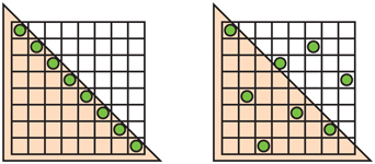
Figure 5.27. N-rooks sampling. On the left is a legal N-rooks pattern, but it performs poorly in capturing triangle edges that are diagonal along its line, as all sample locations will be either inside or outside the triangle as this triangle shifts. On the right is a pattern that will capture this and other edges more effectively.
N-rooks is a start at creating a good sampling pattern, but it is not sufficient. For example, the samples could all be places along the diagonal of a subpixel grid and so give a poor result for edges that are nearly parallel to this diagonal. See Figure 5.27. For better sampling we want to avoid putting two samples near each other. We also want a uniform distribution, spreading samples evenly over the area. To form such patterns, stratified sampling techniques such as Latin hypercube sampling are combined with other methods such as jittering, Halton sequences, and Poisson disk sampling [1413,1758].
In practice GPU manufacturers usually hard-wire such sampling patterns into their hardware for multisampling antialiasing. Figure 5.28 shows some MSAA patterns used in practice.

Figure 5.28. MSAA sampling patterns for AMD and NVIDIA graphics accelerators. The green square is the location of the shading sample, and the red squares are the positional samples computed and saved. From left to right: 2× , 4× , 6× (AMD), and 8× (NVIDIA) sampling. (Generated by the D3D FSAA Viewer.)
For temporal antialiasing, the coverage pattern is whatever the programmer wants, as the sample locations can be varied frame to frame. For example, Karis [862] finds that a basic Halton sequence works better than any MSAA pattern provided by the GPU. A Halton sequence generates samples in space that appear random but have low discrepancy, that is, they are well distributed over the space and none are clustered [1413,1938].
While a subpixel grid pattern results in a better approximation of how each triangle covers a grid cell, it is not ideal. A scene can be made of objects that are arbitrarily small on the screen, meaning that no sampling rate can ever perfectly capture them. If these tiny objects or features form a pattern, sampling at constant intervals can result in Moiré fringes and other interference patterns. The grid pattern used in supersampling is particularly likely to alias.
One solution is to use stochastic sampling, which gives a more randomized pattern. Patterns such as those in Figure 5.28 certainly qualify. Imagine a fine-toothed comb at a distance, with a few teeth covering each pixel. A regular pattern can give severe artifacts as the sampling pattern goes in and out of phase with the tooth frequency. Having a less ordered sampling pattern can break up these patterns. The randomization tends to replace repetitive aliasing effects with noise, to which the human visual system is much more forgiving [1413]. A pattern with less structure helps, but it can still exhibit aliasing when repeated pixel to pixel. One solution is use a different sampling pattern at each pixel, or to change each sampling location over time. Interleaved samplingindexsampling!interleaved, where each pixel of a set has a different sampling pattern, has occasionally been supported in hardware over the past decades. For example, ATI’s SMOOTHVISION allowed up to 16 samples per pixel and up to 16 different user-defined sampling patterns that could be intermingled in a repeating pattern (e.g., in a 4×4 pixel tile). Molnar [1234], as well as Keller and Heidrich [880], found that using interleaved stochastic sampling minimizes the aliasing artifacts formed when using the same pattern for every pixel.
A few other GPU-supported algorithms are worth noting. One real-time antialiasing scheme that lets samples affect more than one pixel is NVIDIA’s older Quincunx method [365]. “Quincunx” means an arrangement of five objects, four in a square and the fifth in the center, such as the pattern of five dots on a six-sided die. Quincunx multisampling antialiasing uses this pattern, putting the four outer samples at the corners of the pixel. See Figure 5.25. Each corner sample value is distributed to its four neighboring pixels. Instead of weighting each sample equally (as most other real-time schemes do), the center sample is given a weight of 12 , and each corner sample has a weight of 18 . Because of this sharing, an average of only two samples are needed per pixel, and the results are considerably better than two-sample FSAA methods [1678]. This pattern approximates a two-dimensional tent filter, which, as discussed in the previous section, is superior to the box filter.
Quincunx sampling can also be applied to temporal antialiasing by using a single sample per pixel [836,1677]. Each frame is offset half a pixel in each axis from the frame before, with the offset direction alternating between frames. The previous frame provides the pixel corner samples, and bilinear interpolation is used to rapidly compute the contribution per pixel. The result is averaged with the current frame. Equal weighting of each frame means there are no shimmer artifacts for a static view. The issue of aligning moving objects is still present, but the scheme itself is simple to code and gives a much better look while using only one sample per pixel per frame.
When used in a single frame, Quincunx has a low cost of only two samples by sharing samples at the pixel boundaries. The RGSS pattern is better at capturing more gradations of nearly horizontal and vertical edges. First developed for mobile graphics, the FLIPQUAD pattern combines both of these desirable features [22]. Its advantages are that the cost is only two samples per pixel, and the quality is similar to RGSS (which costs four samples per pixel). This sampling pattern is shown in Figure 5.29. Other inexpensive sampling patterns that exploit sample sharing are explored by Hasselgren et al. [677].

Figure 5.29. To the left, the RGSS sampling pattern is shown. This costs four samples per pixel. By moving these locations out to the pixel edges, sample sharing can occur across edges. However, for this to work out, every other pixel must have a reflected sample pattern, as shown on the right. The resulting sample pattern is called FLIPQUAD and costs two samples per pixel.
Like Quincunx, the two-sample FLIPQUAD pattern can also be used with temporal antialiasing and spread over two frames. Drobot [382,383,1154] tackles the question of which two-sample pattern is best in his hybrid reconstruction antialiasing (HRAA) work. He explores different sampling patterns for temporal antialiasing, finding the FLIPQUAD pattern to be the best of the five tested. A checkerboard pattern has also seen use with temporal antialiasing. El Mansouri [415] discusses using two-sample MSAA to create a checkerboard render to reduce shader costs while addressing aliasing issues. Jimenez [836] uses SMAA, temporal antialiasing, and a variety of other techniques to provide a solution where antialiasing quality can be changed in response to rendering engine load. Carpentier and Ishiyama [231] sample on edges, rotating the sampling grid by 45∘ . They combine this temporal antialiasing scheme with FXAA (discussed later) to efficiently render on higher-resolution displays.
Morphological Methods
Aliasing often results from edges, such as those formed by geometry, sharp shadows, or bright highlights. The knowledge that aliasing has a structure associated with it can be exploited to give a better antialiased result. In 2009 Reshetov [1483] presented an algorithm along these lines, calling it morphological antialiasing (MLAA). “Morphological” means “relating to structure or shape.” Earlier work had been done in this area [830], as far back as 1983 by Bloomenthal [170]. Reshetov’s paper reinvigorated research into alternatives to multisampling approaches, emphasizing searching for and reconstructing edges [1486].
This form of antialiasing is performed as a post-process. That is, rendering is done in the usual fashion, then the results are fed to a process that generates the antialiased result. A wide range of techniques have been developed since 2009. Those that rely on additional buffers such as depths and normals can provide better results, such as subpixel reconstruction antialiasing (SRAA) [43,829], but are then applicable for antialiasing only geometric edges. Analytical approaches, such as geometry buffer antialiasing (GBAA) and distance-to-edge antialiasing (DEAA), have the renderer compute additional information about where triangle edges are located, e.g., how far the edge is from the center of the pixel [829].
The most general schemes need only the color buffer, meaning they can also improve edges from shadows, highlights, or various previously applied post-processing techniques, such as silhouette edge rendering (Section ). For example, directionally localized antialiasing (DLAA) [52,829] is based on the observation that an edge which is nearly vertical should be blurred horizontally, and likewise nearly horizontal edges should be blurred vertically with their neighbors.
More elaborate forms of edge detection attempt to find pixels likely to contain an edge at any angle and determine its coverage. The neighborhoods around potential edges are examined, with the goal of reconstructing as possible where the original edge was located. The edge’s effect on the pixel can then be used to blend in neighboring pixels’ colors. See Figure 5.30 for a conceptual view of the process.

Figure 5.30. Morphological antialiasing. On the left is the aliased image. The goal is to determine the likely orientation of the edge that formed it. In the middle, the algorithm notes the likelihood of an edge by examining neighbors. Given the samples, two possible edge locations are shown. On the right, a best-guess edge is used to blend neighboring colors into the center pixel in proportion to the estimated coverage. This process is repeated for every pixel in the image.
Iourcha et al. [798] improve edge-finding by examine the MSAA samples in pixels to compute a better result. Note that edge prediction and blending can give a higher-precision result than sample-based algorithms. For example, a technique that uses four samples per pixel can give only five levels of blending for an object’s edge: no samples covered, one covered, two, three, and four. The estimated edge location can have more locations and so provide better results.
There are several ways image-based algorithms can go astray. First, the edge may not be detected if the color difference between two objects is lower than the algorithm’s threshold. Pixels where there are three or more distinct surfaces overlapping are difficult to interpret. Surfaces with high-contrast or high-frequency elements, where the color is changing rapidly from pixel to pixel, can cause algorithms to miss edges. In particular, text quality usually suffers when morphological antialiasing is applied to it. Object corners can be a challenge, with some algorithms giving them a rounded appearance. Curved lines can also be adversely affected by the assumption that edges are straight. A single pixel change can cause a large shift in how the edge is reconstructed, which can create noticeable artifacts frame to frame. One approach to ameliorate this problem is to use MSAA coverage masks to improve edge determination [1484].
Morphological antialiasing schemes use only the information that is provided. For example, an object thinner than a pixel in width, such as an electrical wire or rope, will have gaps on the screen wherever it does not happen to cover the center location of a pixel. Taking more samples can improve the quality in such situations; image-based antialiasing alone cannot. In addition, execution time can be variable depending on what content is viewed. For example, a view of a field of grass can take three times as long to antialias as a view of the sky [231].
All this said, image-based methods can provide antialiasing support for modest memory and processing costs, so they are used in many applications. The color-only versions are also decoupled from the rendering pipeline, making them easy to modify or disable, and can even be exposed as GPU driver options. The two most popular algorithms are fast approximate antialiasing (FXAA) [1079,1080,1084], and subpixel morphological antialiasing (SMAA) [828,830,834], in part because both provide solid (and free) source code implementations for a variety of machines. Both algorithms use color-only input, with SMAA having the advantage of being able to access MSAA samples. Each has its own variety of settings available, trading off between speed and quality. Costs are generally in the range of 1 to 2 milliseconds per frame, mainly because that is what video games are willing to spend. Finally, both algorithms can also take advantage of temporal antialiasing [1812]. Jimenez [836] presents an improved SMAA implementation, faster than FXAA, and describes a temporal antialiasing scheme. To conclude, we recommend the reader to the wide-ranging review by Reshetov and Jimenez [1486] of morphological techniques and their use in video games.
5.5 Transparency, Alpha, and Compositing
There are many different ways in which semitransparent objects can allow light to pass through them. For rendering algorithms, these can be roughly divided into light-based and view-based effects. Light-based effects are those in which the object causes light to be attenuated or diverted, causing other objects in the scene to be lit and rendered differently. View-based effects are those in which the semitransparent object itself is being rendered.
In this section we will deal with the simplest form of view-based transparency, in which the semitransparent object acts as an attenuator of the colors of the objects behind it. More elaborate view- and light-based effects such as frosted glass, the bending of light (refraction), attenuation of light due to the thickness of the transparent object, and reflectivity and transmission changes due to the viewing angle are discussed in later chapters.
One method for giving the illusion of transparency is called screen-door transparency [1244]. The idea is to render the transparent triangle with a pixel-aligned checkerboard fill pattern. That is, every other pixel of the triangle is rendered, thereby leaving the object behind it partially visible. Usually the pixels on the screen are close enough together that the checkerboard pattern itself is not visible. A major drawback of this method is that often only one transparent object can be convincingly rendered on one area of the screen. For example, if a transparent red object and transparent green object are rendered atop a blue object, only two of the three colors can appear on the checkerboard pattern. Also, the 50% checkerboard is limiting. Other larger pixel masks could be used to give other percentages, but these tend to create detectable patterns [1245].
That said, one advantage of this technique is its simplicity. Transparent objects can be rendered at any time, in any order, and no special hardware is needed. The transparency problem goes away by making all objects opaque at the pixels they cover. This same idea is used for antialiasing edges of cutout textures, but at a subpixel level, using a feature called alpha to coverage (Section ).
Introduced by Enderton et al. [423], stochastic transparency uses subpixel screen-door masks combined with stochastic sampling. A reasonable, though noisy, image is created by using random stipple patterns to represent the alpha coverage of the fragment. See Figure 5.31. A large number of samples per pixel is needed for the result to look reasonable, as well as a sizable amount of memory for all the subpixel samples. What is appealing is that no blending is needed, and antialiasing, transparency, and any other phenomena that creates partially covered pixels are covered by a single mechanism.

Figure 5.31. Stochastic transparency. The noise produced is displayed in the magnified area. (Images from NVIDIA SDK 11 [1301] samples, courtesy of NVIDIA Corporation.)
Most transparency algorithms blend the transparent object’s color with the color of the object behind it. For this, the concept of alpha blending is needed [199,387,1429]. When an object is rendered on the screen, an RGB color and a z-buffer depth are associated with each pixel. Another component, called alpha ( α ), can also be defined for each pixel the object covers. Alpha is a value describing the degree of opacity and coverage of an object fragment for a given pixel. An alpha of 1.0 means the object is opaque and entirely covers the pixel’s area of interest; 0.0 means the pixel is not obscured at all, i.e., the fragment is entirely transparent.
A pixel’s alpha can represent either opacity, coverage, or both, depending on the circumstances. For example, the edge of a soap bubble may cover three-quarters of the pixel, 0.75, and may be nearly transparent, letting nine-tenths of the light through to the eye, so it is one-tenth opaque, 0.1. Its alpha would then be 0.75×0.1=0.075 . However, if we were using MSAA or similar antialiasing schemes, the coverage would be taken into account by the samples themselves. Three-quarters of the samples would be affected by the soap bubble. At each of these samples we would then use the 0.1 opacity value as the alpha.
5.5.1. Blending Order
To make an object appear transparent, it is rendered on top of the existing scene with an alpha of less than 1.0. Each pixel covered by the object will receive a resulting RGB α (also called RGBA) from the pixel shader. Blending this fragment’s value with the original pixel color is usually done using the over operator, as follows:
(5.24)
co=αscs+(1-αs)cd[overoperator],where cs is the color of the transparent object (called the source), αs is the object’s alpha, cd is the pixel color before blending (called the destination), and co is the resulting color due to placing the transparent object over the existing scene. In the case of the rendering pipeline sending in cs and αs , the pixel’s original color cd gets replaced by the result co . If the incoming RGB α is, in fact, opaque ( αs=1.0 ), the equation simplifies to the full replacement of the pixel’s color by the object’s color.
EXAMPLE: BLENDING. A red semitransparent object is rendered onto a blue background. Say that at some pixel the RGB shade of the object is (0.9, 0.2, 0.1), the background is (0.1, 0.1, 0.9), and the object’s opacity is set at 0.6. The blend of these two colors is then
which gives a color of (0.58, 0.16, 0.42).
The over operator gives a semitransparent look to the object being rendered. Transparency done this way works, in the sense that we perceive something as transparent whenever the objects behind can be seen through it [754]. Using over simulates the real-world effect of a gauzy fabric. The view of the objects behind the fabric are partially obscured—the fabric’s threads are opaque. In practice, loose fabric has an alpha coverage that varies with angle [386]. Our point here is that alpha simulates how much the material covers the pixel.
The over operator is less convincing simulating other transparent effects, most notably viewing through colored glass or plastic. A red filter held in front of a blue object in the real world usually makes the blue object look dark, as this object reflects little light that can pass through the red filter. See Figure 5.32.

Figure 5.32. A red gauzy square of fabric and a red plastic filter, giving different transparency effects. Note how the shadows also differ. (Photograph courtesy of Morgan McGuire.)
When over is used for blending, the result is a portion of the red and the blue added together. It would be better to multiply the two colors together, as well as adding in any reflection off the transparent object itself. This type of physical transmittance is discussed in Sections 14.5.1 and 14.5.2.
Of the basic blend stage operators, over is the one commonly used for a transparency effect [199,1429]. Another operation that sees some use is additive blending, where pixel values are simply summed. That is,
(5.25)
co=αscs+cd.This blending mode can work well for glowing effects such as lightning or sparks that do not attenuate the pixels behind but instead only brighten them [1813]. However, this mode does not look correct for transparency, as the opaque surfaces do not appear filtered [1192]. For several layered semitransparent surfaces, such as smoke or fire, additive blending has the effect of saturating the colors of the phenomenon [1273].
To render transparent objects properly, we need to draw them after the opaque objects. This is done by rendering all opaque objects first with blending off, then rendering the transparent objects with over turned on. In theory we could always have over on, since an opaque alpha of 1.0 would give the source color and hide the destination color, but doing so is more expensive, for no real gain.
A limitation of the z-buffer is that only one object is stored per pixel. If several transparent objects overlap the same pixel, the z-buffer alone cannot hold and later resolve the effect of all the visible objects. When using over the transparent surfaces at any given pixel generally need to be rendered in back-to-front order. Not doing so can give incorrect perceptual cues. One way to achieve this ordering is to sort individual objects by, say, the distance of their centroids along the view direction. This rough sorting can work reasonably well, but has a number of problems under various circumstances. First, the order is just an approximation, so objects classified as more distant may be in front of objects considered nearer. Objects that interpenetrate are impossible to resolve on a per-mesh basis for all view angles, short of breaking each mesh into separate pieces. See the left image in Figure 5.33 for an example.

Figure 5.33. On the left the model is rendered with transparency using the z-buffer. Rendering the mesh in an arbitrary order creates serious errors. On the right, depth peeling provides the correct appearance, at the cost of additional passes. (Images courtesy of NVIDIA Corporation.)
Even a single mesh with concavities can exhibit sorting problems for view directions where it overlaps itself on the screen.
Nonetheless, because of its simplicity and speed, as well as needing no additional memory or special GPU support, performing a rough sort for transparency is still commonly used. If implemented, it is usually best to turn off z-depth replacement when performing transparency. That is, the z-buffer is still tested normally, but surviving surfaces do not change the z-depth stored; the closest opaque surface’s depth is left intact. In this way, all transparent objects will at least appear in some form, versus suddenly appearing or disappearing when a camera rotation changes the sort order. Other techniques can also help improve the appearance, such as drawing each transparent mesh twice as you go, first rendering backfaces and then frontfaces [1192,1255].
The over equation can also be modified so that blending front to back gives the same result. This blending mode is called the under operator:
(5.26)
co=αdcd+(1-αd)αscs[underoperator],ao=αs(1-αd)+αd=αs-αsαd+αd.Note that under requires the destination to maintain an alpha value, which over does not. In other words, the destination—the closer transparent surface being blended under—is not opaque and so needs to have an alpha value. The under formulation is like over, but with source and destination swapped. Also, notice that the formula for computing alpha is order-independent, in that the source and destination alphas can be swapped, with the same final alpha being the result.

Figure 5.34. A pixel and two fragments, s and d. By aligning the two fragments along different axes, each fragment covers a proportional amount of the other, i.e., they are uncorrelated. The area covered by the two fragments is equivalent to the under output alpha value αs-αsαd+αd . This translates to adding the two areas, then subtracting the area where they overlap.
The equation for alpha comes from considering the fragment’s alphas as coverages. Porter and Duff [1429] note that since we do not know the shape of the coverage area for either fragment, we assume that each fragment covers the other in proportion to its alpha. For example, if αs=0.7 , the pixel is somehow divided into two areas, with 0.7 covered by the source fragment and 0.3 not. Barring any other knowledge, the destination fragment covering, say, αd=0.6 will be proportionally overlapped by the source fragment. This formula has a geometric interpretation, shown in Figure 5.34.
5.5.2. Order-Independent Transparency
The under equations are used by drawing all transparent objects to a separate color buffer, then merging this color buffer atop the opaque view of the scene using over. Another use of the under operator is for performing an order-independent transparency (OIT) algorithm known as depth peeling [449,1115]. Order-independent means that the application does not need to perform sorting. The idea behind depth peeling is to use two z-buffers and multiple passes. First, a rendering pass is made so that all surfaces’ z-depths, including transparent surfaces, are in the first z-buffer. In the second pass all transparent objects are rendered. If the z-depth of an object matches the value in the first z-buffer, we know this is the closest transparent object and save its RGB α to a separate color buffer. We also “peel” this layer away by saving the z-depth of whichever transparent object, if any, is beyond the first z-depth and is closest. This z-depth is the distance of the second-closest transparent object. Successive passes continue to peel and add transparent layers using under. We stop after some number of passes and then blend the transparent image atop the opaque image. See Figure 5.35.

Figure 5.35. Each depth peel pass draws one of the transparent layers. On the left is the first pass, showing the layer directly visible to the eye. The second layer, shown in the middle, displays the second-closest transparent surface at each pixel, in this case the backfaces of objects. The third layer, on the right, is the set of third-closest transparent surfaces. Final results can be found in Figure 14.33 on page 624. (Images courtesy of Louis Bavoil.)
Several variants on this scheme have been developed. For example, Thibieroz [1763] gives an algorithm that works back to front, which has the advantage of being able to blend the transparent values immediately, meaning that no separate alpha channel is needed. One problem with depth peeling is knowing how many passes are sufficient to capture all the transparent layers. One hardware solution is to provide a pixel draw counter, which tells how many pixels were written during rendering; when no pixels are rendered by a pass, rendering is done. The advantage of using under is that the most important transparent layers—those the eye first sees—are rendered early on. Each transparent surface always increases the alpha value of the pixel it covers. If the alpha value for a pixel nears 1.0, the blended contributions have made the pixel almost opaque, and so more distant objects will have a negligible effect [394]. Front-to-back peeling can be cut short when the number of pixels rendered by a pass falls below some minimum, or a fixed number of passes can be specified. This does not work as well with back-to-front peeling, as the closest (and usually most important) layers are drawn last and so may be lost by early termination.
While depth peeling is effective, it can be slow, as each layer peeled is a separate rendering pass of all transparent objects. Bavoil and Myers [118] presented dual depth peeling, where two depth peel layers, the closest and the farthest remaining, are stripped off in each pass, thus cutting the number of rendering passes in half. Liu et al. [1056] explore a bucket sort method that captures up to 32 layers in a single pass. One drawback of this type of approach is that it needs considerable memory to keep a sorted order for all layers. Antialiasing via MSAA or similar would increase the costs astronomically.
The problem of blending transparent objects together properly at interactive rates is not one in which we are lacking algorithms, it is one of efficiently mapping those algorithms to the GPU. In 1984 Carpenter presented the A-buffer [230], another form of multisampling. In the A-buffer, each triangle rendered creates a coverage mask for each screen grid cell it fully or partially covers. Each pixel stores a list of all relevant fragments. Opaque fragments can cull out fragments behind them, similar to the z-buffer. All the fragments are stored for transparent surfaces. Once all lists are formed, a final result is produced by walking through the fragments and resolving each sample.
The idea of creating linked lists of fragments on the GPU was made possible through new functionality exposed in DirectX 11 [611,1765]. The features used include unordered access views (UAVs) and atomic operations, described in Section 3.8. Antialiasing via MSAA is enabled by the ability to access the coverage mask and to evaluate the pixel shader at every sample. This algorithm works by rasterizing each transparent surface and inserting the fragments generated in a long array. Along with the colors and depths, a separate pointer structure is generated that links each fragment to the previous fragment stored for the pixel. A separate pass is then performed, where a screen-filling quadrilateral is rendered so that a pixel shader is evaluated at every pixel. This shader retrieves all the transparent fragments at each pixel by following the links. Each fragment retrieved is sorted in turn with the previous fragments. This sorted list is then blended back to front to give the final pixel color. Because blending is performed by the pixel shader, different blend modes can be specified per pixel, if desired. Continuing evolution of the GPU and APIs have improved performance by reducing the cost of using atomic operators [914].
The A-buffer has the advantage that only the fragments needed for each pixel are allocated, as does the linked list implementation on the GPU. This in a sense can also be a disadvantage, as the amount of storage required is not known before rendering of a frame begins. A scene with hair, smoke, or other objects with a potential for many overlapping transparent surfaces can produce a huge number of fragments. Andersson [46] notes that, for complex game scenes, up to 50 transparent meshes of objects such as foliage and up to 200 semitransparent particles may overlap.
GPUs normally have memory resources such as buffers and arrays allocated in advance, and linked-list approaches are no exception. Users need to decide how much memory is enough, and running out of memory causes noticeable artifacts. Salvi and Vaidyanathan [1532] present an approach tackling this problem, multi-layer alpha blending, using a GPU feature introduced by Intel called pixel synchronization. See Figure 5.36. This capability provides programmable blending with less overhead than atomics. Their approach reformulates storage and blending so that it gracefully degrades if memory runs out. A rough sort order can benefit their scheme. DirectX 11.3 introduced rasterizer order views (Section ), a type of buffer that allows this transparency method to be implemented on any GPU supporting this feature [327,328]. Mobile devices have a similar technology called tile local storage that permits them to implement multi-layer alpha blending [153]. Such mechanisms have a performance cost, however, so this type of algorithm can be expensive [1931].

Figure 5.36. In the upper left, traditional back-to-front alpha blending is performed, leading to rendering errors due to incorrect sort order. In the upper right, the A-buffer is used to give a perfect, non-interactive result. The lower left presents the rendering with multi-layer alpha blending. The lower right shows the differences between the A-buffer and multi-layer images, multiplied by 4 for visibility [1532]. (Images courtesy of Marco Salvi and Karthik Vaidyanathan, Intel Corporation.)
This approach builds on the idea of the k-buffer, introduced by Bavoil et al. [115], where the first few visible layers are saved and sorted as possible, with deeper layers discarded and merged as possible. Maule et al. [1142] use a k-buffer and account for these more distant deep layers by using weighted averaging. Weighted sum [1202] and weighted average [118] transparency techniques are order-independent, are single-pass, and run on almost every GPU. The problem is that they do not take into account the ordering of the objects. So, for example, using alpha to represent coverage, a gauzy red scarf atop a gauzy blue scarf gives a violet color, versus properly seeing a red scarf with a little blue showing through. While nearly opaque objects give poor results, this class of algorithms is useful for visualization and works well for highly transparent surfaces and particles. See Figure 5.37.

Figure 5.37. The object order becomes more important as opacity increases. (Images after Dunn [394].)
In weighted sum transparency the formula is
(5.27)
co=∑ni=1(αici)+cd(1-∑ni=1αi),where n is the number of transparent surfaces, ci and αi represent the set of transparency values, and cd is the color of the opaque portion of the scene. The two sums are accumulated and stored separately as transparent surfaces are rendered, and at the end of the transparency pass, the equation is evaluated at each pixel. Problems with this method are that the first sum saturates, i.e., generates color values greater than (1.0, 1.0, 1.0), and that the background color can have a negative effect, since the sum of the alphas can surpass 1.0.
The weighted average equation is usually preferred because it avoids these problems:
(5.28)
csum=n∑i=1(αici),αsum=n∑i=1αi,cwavg=csumαsum,αavg=αsumn,u=(1-αavg)n,co=(1-u)cwavg+ucd.The first line represents the results in the two separate buffers generated during transparency rendering. Each surface contributing to csum is given an influence weighted by its alpha; nearly opaque surfaces contribute more of their color, and nearly transparent surfaces have little influence. By dividing csum by αsum we get a weighted average transparency color. The value αavg is the average of all alpha values. The value u is the estimated visibility of the destination (the opaque scene) after this average alpha is applied n times, for n transparent surfaces. The final line is effectively the over operator, with (1-u) representing the source’s alpha.
One limitation with weighted average is that, for identical alphas, it blends all colors equally, regardless of order. McGuire and Bavoil [1176,1180] introduced weighted blended order-independent transparency to give a more convincing result. In their formulation, the distance to the surface also affects the weight, with closer surfaces given more influence. Also, rather than averaging the alphas, u is computed by multiplying the terms (1-αi) together and subtracting from one, giving the true alpha coverage of the set of surfaces. This method produces more visually convincing results, as seen in Figure 5.38.
A drawback is that objects close to one another in a large environment can have nearly equal weightings from distance, making the result little different than the weighted average. Also, as the camera’s distance to the transparent objects changes, the depth weightings may then vary in effect, but this change is gradual.

Figure 5.38. Two different camera locations viewing the same engine model, both rendered with weighted blended order-independent transparency. Weighting by distance helps clarify which surfaces are closer to the viewer [1185]. (Images courtesy of Morgan McGuire.)
McGuire and Mara [1181,1185] extend this method to include a plausible transmission color effect. As noted earlier, all the transparency algorithms discussed in this section blend various colors instead of filtering them, mimicking pixel coverage. To give a color filter effect, the opaque scene is read by the pixel shader and each transparent surface multiplies the pixels it covers in this scene by its color, saving the result to a third buffer. This buffer, in which the opaque objects are now tinted by the transparent ones, is then used in place of the opaque scene when resolving the transparency buffers. This method works because, unlike transparency due to coverage, colored transmission is order-independent.
There are yet other algorithms that use elements from several of the techniques presented here. For example, Wyman [1931] categorizes previous work by memory requirements, insertion and merge methods, whether alpha or geometric coverage is used, and how discarded fragments are treated. He presents two new methods found by looking for gaps in previous research. His stochastic layered alpha blending method uses k-buffers, weighted average, and stochastic transparency. His other algorithm is a variant on Salvi and Vaidyanathan’s method, using coverage masks instead of alpha.
Given the wide variety of types of transparent content, rendering methods, and GPU capabilities, there is no perfect solution for rendering transparent objects. We refer the interested reader to Wyman’s paper [1931] and Maule et al.’s more detailed survey [1141] of algorithms for interactive transparency. McGuire’s presentation [1182] gives a wider view of the field, running through other related phenomena such as volumetric lighting, colored transmission, and refraction, which are discussed in greater depth later in this book.
5.5.3. Premultiplied Alphas and Compositing
The over operator is also used for blending together photographs or synthetic renderings of objects. This process is called compositing [199,1662]. In such cases, the alpha value at each pixel is stored along with the RGB color value for the object. The image formed by the alpha channel is sometimes called the matte. It shows the silhouette shape of the object. See Figure on page for an example. This RGB α image can then be used to blend it with other such elements or against a background.
One way to use synthetic RGB α data is with premultiplied alphas (also known as associated alphas). That is, the RGB values are multiplied by the alpha value before being used. This makes the compositing over equation more efficient:
(5.29)
co=c′s+(1-αs)cd,where c′s is the premultiplied source channel, replacing αscs in Equation 5.25. Premultiplied alpha also makes it possible to use over and additive blending without changing the blend state, since the source color is now added in during blending [394]. Note that with premultiplied RGB α values, the RGB components are normally not greater than the alpha value, though they can be made so to create a particularly bright semitransparent value.
Rendering synthetic images dovetails naturally with premultiplied alphas. An antialiased opaque object rendered over a black background provides premultiplied values by default. Say a white (1, 1, 1) triangle covers 40% of some pixel along its edge. With (extremely precise) antialiasing, the pixel value would be set to a gray of 0.4, i.e., we would save the color (0.4, 0.4, 0.4) for this pixel. The alpha value, if stored, would also be 0.4, since this is the area the triangle covered. The RGB α value would be (0.4, 0.4, 0.4, 0.4), which is a premultiplied value.
Another way images are stored is with unmultiplied alphas, also known as unassociated alphas or even as the mind-bending term nonpremultiplied alphas. An unmultiplied alpha is just what it says: The RGB value is not multiplied by the alpha value. For the white triangle example, the unmultiplied color would be (1, 1, 1, 0.4). This representation has the advantage of storing the triangle’s original color, but this color always needs to be multiplied by the stored alpha before being display. It is best to use premultiplied data whenever filtering and blending is performed, as operations such as linear interpolation do not work correctly using unmultiplied alphas [108,164]. Artifacts such as black fringes around the edges of objects can result [295,648]. See the end of Section for further discussion. Premultiplied alphas also allow cleaner theoretical treatment [1662].
For image-manipulation applications, an unassociated alpha is useful to mask a photograph without affecting the underlying image’s original data. Also, an unassociated alpha means that the full precision range of the color channels can be used. That said, care must be taken to properly convert unmultiplied RGB α values to and from the linear space used for computer graphics computations. For example, no browsers do this properly, nor are they ever likely to do so, since the incorrect behavior is now expected [649]. Image file formats that support alpha include PNG (unassociated alpha only), OpenEXR (associated only), and TIFF (both types of alpha).
A concept related to the alpha channel is chroma-keying [199]. This is a term from video production, in which actors are filmed against a green or blue screen and blended with a background. In the film industry this process is called green-screening or blue-screening. The idea here is that a particular color hue (for film work) or precise value (for computer graphics) is designated to be considered transparent; the background is displayed whenever it is detected. This allows images to be given an outline shape by using just RGB colors; no alpha needs to be stored. One drawback of this scheme is that the object is either entirely opaque or transparent at any pixel, i.e., alpha is effectively only 1.0 or 0.0. As an example, the GIF format allows one color to be designated as transparent.
5.6 Display Encoding
When we calculate the effect of lighting, texturing, or other operations, the values used are assumed to be linear. Informally, this means that addition and multiplication work as expected. However, to avoid a variety of visual artifacts, display buffers and textures use nonlinear encodings that we must take into account. The short and sloppy answer is as follows: Take shader output colors in the range [0, 1] and raise them by a power of 1 / 2.2, performing what is called gamma correction. Do the opposite for incoming textures and colors. In most cases you can tell the GPU to do these things for you. This section explains the how and why of that quick summary.
We begin with the cathode-ray tube (CRT). In the early years of digital imaging, CRT displays were the norm. These devices exhibit a power law relationship between input voltage and display radiance. As the energy level applied to a pixel is increased, the radiance emitted does not grow linearly but (surprisingly) rises proportional to that level raised to a power greater than one. For example, imagine the power is 2. A pixel set to 50% will emit a quarter the amount of light, 0.52=0.25 , as a pixel that is set to 1.0 [607]. Although LCDs and other display technologies have different intrinsic tone response curves than CRTs, they are manufactured with conversion circuitry that causes them to mimic the CRT response.
This power function nearly matches the inverse of the lightness sensitivity of human vision [1431]. The consequence of this fortunate coincidence is that the encoding is roughly perceptually uniform. That is, the perceived difference between a pair of encoded values N and N+1 is roughly constant over the displayable range. Measured as threshold contrast, we can detect a difference in lightness of about 1% over a wide range of conditions. This near-optimal distribution of values minimizes banding artifacts when colors are stored in limited-precision display buffers (Section ). The same benefit also applies to textures, which commonly use the same encoding.
The display transfer function describes the relationship between the digital values in the display buffer and the radiance levels emitted from the display. For this reason it is also called the electrical optical transfer function (EOTF). The display transfer function is part of the hardware, and there are different standards for computer monitors, televisions, and film projectors. There is also a standard transfer function for the other end of the process, image and video capture devices, called the optical electric transfer function (OETF) [672].
When encoding linear color values for display, our goal is to cancel out the effect of the display transfer function, so that whatever value we compute will emit a corresponding radiance level. For example, if our computed value is doubled, we want the output radiance to be doubled. To maintain this connection, we apply the inverse of the display transfer function to cancel out its nonlinear effect. This process of nullifying the display’s response curve is also called gamma correction, for reasons that will become clear shortly. When decoding texture values, we need to apply the display transfer function to generate a linear value for use in shading. Figure 5.39 shows the use of decoding and encoding in the display process.

Figure 5.39. On the left, a PNG color texture is accessed by a GPU shader, and its nonlinearly encoded value is converted (blue) to a linear value. After shading and tone mapping (Section ), the final computed value is encoded (green) and stored in the framebuffer. This value and the display transfer function determine the amount of radiance emitted (red). The green and red functions combined cancel out, so that the radiance emitted is proportional to the linear computed value.
The standard transfer function for personal computer displays is defined by a color-space specification called sRGB. Most APIs controlling GPUs can be set to automatically apply the proper sRGB conversion when values are read from textures or written to the color buffer [491]. As discussed in Section 6.2.2, mipmap generation will also take sRGB encoding into account. Bilinear interpolation among texture values will work correctly, by first converting to linear values and then performing the interpolation. Alpha blending is done correctly by decoding the stored value back into linear values, blending in the new value, and then encoding the result.
It is important to apply the conversion at the final stage of rendering, when the values are written to the framebuffer for the display. If post-processing is applied after display encoding, such effects will be computed on nonlinear values, which is usually incorrect and will often cause artifacts. Display encoding can be thought of as a form of compression, one that best preserves the value’s perceptual effect [491]. A good way to think about this area is that there are linear values that we use to perform physical computations, and whenever we want to display results or access displayable images such as color textures, we need to move data to or from its display-encoded form, using the proper encode or decode transform.
If you do need to apply sRGB manually, there is a standard conversion equation or a few simplified versions that can be used. In practical terms the display is controlled by a number of bits per color channel, e.g., 8 for consumer-level monitors, giving a set of levels in the range [0, 255]. Here we express the display-encoded levels as a range [0.0, 1.0], ignoring the number of bits. The linear values are also in the range [0.0, 1.0], representing floating point numbers. We denote these linear values by x and the nonlinearly encoded values stored in the framebuffer by y. To convert linear values to sRGB nonlinear encoded values, we apply the inverse of the sRGB display transfer function:
(5.30)
y=fsRGB-1(x)={1.055x1/2.4-0.055,wherex>0.0031308,12.92x,wherex≤0.0031308,with x representing a channel of the linear RGB triplet. The equation is applied to each channel, and these three generated values drive the display. Be careful if you apply conversion functions manually. One source of error is using an encoded color instead of its linear form, and another is decoding or encoding a color twice.
The bottom of the two transform expressions is a simple multiply, which arises from a need by digital hardware to make the transform perfectly invertible [1431]. The top expression, involving raising the value to a power, applies to almost the whole range [0.0, 1.0] of input values x. With the offset and scale taken into account, this function closely approximates a simpler formula [491]:
(5.31)
y=fdisplay-1(x)=x1/γ,with γ=2.2 . The Greek letter γ is the basis for the name “gamma correction.”
Just as computed values must be encoded for display, images captured by still or video cameras must be converted to linear values before being used in calculations. Any color you see on a monitor or television has some display-encoded RGB triplet that you can obtain from a screen capture or color picker. These values are what are stored in file formats such as PNG, JPEG, and GIF, formats that can be directly sent to a framebuffer for display on the screen without conversion. In other words, whatever you see on the screen is by definition display-encoded data. Before using these colors in shading calculations, we must convert from this encoded form back to linear values. The sRGB transformation we need from display encoding to linear values is
(5.32)
x=fsRGB(y)={(y+0.0551.055)2.4,wherey>0.04045,y12.92,wherey≤0.04045,with y representing a normalized displayed channel value, i.e., what is stored in an image or framebuffer, expressed as a value in the range [0.0, 1.0]. This decode function is the inverse of our previous sRGB formula. This means that if a texture is accessed by a shader and output without change, it will appear the same as before being processed, as expected. The decode function is the same as the display transfer function because the values stored in a texture have been encoded to display correctly. Instead of converting to give a linear-response display, we are converting to give linear values.
The simpler gamma display transfer function is the inverse of Equation 5.31:
(5.33)
x=fdisplay(y)=yγ.Sometimes you will see a conversion pair that is simpler still, particularly on mobile and browser apps [1666]:
(5.34)
y=fsimpl-1(x)=√x,x=fsimpl(y)=y2;that is, take the square root of the linear value for conversion for display, and just multiply the value by itself for the inverse. While a rough approximation, this conversion is better than ignoring the problem altogether.
If we do not pay attention to gamma, lower linear values will appear too dim on the screen. A related error is that the hue of some colors can shift if no gamma correction is performed. Say our . We want to emit a radiance from the displayed pixel proportional to the linear, computed value, which means that we must raise the linear value to the (1 / 2.2) power. A linear value of 0.1 gives 0.351, 0.2 gives 0.481, and 0.5 gives 0.730. If not encoded, these values used as is will cause the display to emit less radiance than needed. Note that 0.0 and 1.0 are always unchanged by any of these transforms. Before gamma correction was used, dark surface colors would often be artificially boosted by the person modeling the scene, folding in the inverse display transform.
Another problem with neglecting gamma correction is that shading computations that are correct for physically linear radiance values are performed on nonlinear values. An example of this can be seen in Figure 5.40.

Figure 5.40. Two overlapping spotlights illuminating a plane. In the left image, gamma correction is not performed after adding the light values of 0.6 and 0.4. The addition is effectively performed on nonlinear values, causing errors. Note how the left light looks considerably brighter than the right, and the overlap appears unrealistically bright. In the right image, the values are gamma corrected after addition. The lights themselves are proportionally brighter, and they combine properly where they overlap.
Ignoring gamma correction also affects the quality of antialiased edges. For example, say a triangle edge covers four screen grid cells (Figure 5.41).

Figure 5.41. On the left, four pixels covered by the edge of a white triangle on a black (shown as gray) background, with true area coverage shown. If gamma correction is not performed, the darkening of midtones will cause the perception of the edge to be distorted, as seen on the right.
The triangle’s normalized radiance is 1 (white); the background’s is 0 (black). Left to right, the cells are covered , , , and . So, if we are using a box filter, we want to represent the normalized linear radiance of the pixels as 0.125, 0.375, 0.625, and 0.875. The correct approach is to perform antialiasing on linear values, applying the encoding function to the four resulting values. If this is not done, the represented radiance for the pixels will be too dark, resulting in a perceived deformation of the edge as seen in the right side of the figure. This artifact is called roping, because the edge looks somewhat like a twisted rope [167,1265]. Figure 5.42 shows this effect.

Figure 5.42. On the left, the set of antialiased lines are gamma-corrected; in the middle, the set is partially corrected; on the right, there is no gamma correction. (Images courtesy of Scott R. Nelson.)
The sRGB standard was created in 1996 and has become the norm for most computer monitors. However, display technology has evolved since that time. Monitors that are brighter and that can display a wider range of colors have been developed. Color display and brightness are discussed in Section 8.1.3, and display encoding for high dynamic range displays is presented in Section 8.2.1. Hart’s article [672] is a particularly thorough source for more information about advanced displays.
Further Reading and Resources
Pharr et al. [1413] discuss sampling patterns and antialiasing in more depth. Teschner’s course notes [1758] show various sampling pattern generation methods. Drobot [382,383] runs through previous research on real-time antialiasing, explaining the attributes and performance of a variety of techniques. Information on a wide variety of morphological antialiasing methods can be found in the notes for the related SIGGRAPH course [829]. Reshetov and Jimenez [1486] provide an updated retrospective of morphological and related temporal antialiasing work used in games.
For transparency research we again refer the interested reader to McGuire’s presentation [1182] and Wyman’s work [1931]. Blinn’s article “What Is a Pixel?” [169] provides an excellent tour of several areas of computer graphics while discussing different definitions. Blinn’s Dirty Pixels and Notation, Notation, Notation books [166,168] include some introductory articles on filtering and antialiasing, as well as articles on alpha, compositing, and gamma correction. Jimenez’s presentation [836] gives a detailed treatment of state-of-the-art techniques used for antialiasing.
Gritz and d’Eon [607] have an excellent summary of gamma correction issues. Poynton’s book [1431] gives solid coverage of gamma correction in various media, as well as other color-related topics. Selan’s white paper [1602] is a newer source, explaining display encoding and its use in the film industry, along with much other related information.