
14
CHAPTER
Capacitive Reactance
CAPACITIVE REACTANCE ACTS AS THE NATURAL COUNTERPART OF INDUCTIVE REACTANCE. WE CAN represent it graphically as a ray that goes in a negative direction. When we join the capacitive-reactance and inductive-reactance rays at their end points (both of which correspond to a reactance of zero), we get a complete number line, as shown in Fig. 14-1. This line depicts all possible values of reactance because any nonzero reactance must be either inductive or capacitive.

14-1 We can represent inductive and capacitive reactance values as points along a number line.
Capacitors and Direct Current
Imagine two huge, flat metal plates, both of which constitute excellent electrical conductors. If we connect them to a source of DC, as shown in Fig. 14-2, they draw a large amount of current while they become electrically charged. But as the plates reach equilibrium, the charging current goes down to zero.
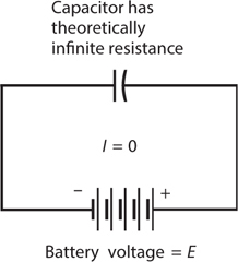
14-2 A capacitor connected across a source of DC.
If we increase the voltage of the battery or power supply, we eventually reach a point at which sparks jump between the plates of our capacitor. Ultimately, if the power supply can deliver the necessary voltage, this sparking, or arcing, becomes continuous. Under these conditions, the pair of plates no longer acts like a capacitor at all. When we place excessive voltage across a capacitor, the dielectric can’t provide electrical separation between the plates. We call this undesirable condition dielectric breakdown.
In an air-dielectric or vacuum-dielectric capacitor, dielectric breakdown manifests itself as a temporary affair, rarely causing permanent damage to the component. The device operates normally after we reduce the voltage so that the arcing stops. However, in capacitors made with solid dielectric materials, such as mica, paper, polystyrene, or tantalum, dielectric breakdown can burn or crack the dielectric, causing the component to conduct current even after we reduce the voltage. If a capacitor suffers this sort of damage, we must remove it from the circuit, discard it, and replace it with a new one.
Capacitors and Alternating Current
Now suppose that we change the voltage source from DC to AC (Fig. 14-3). Imagine that we can adjust the frequency of this AC from a low initial value of a few hertz, up to hundreds of hertz, then to many kilohertz, megahertz, or gigahertz.

14-3 A capacitor connected across a source of AC.
At first, the voltage between the plates follows the voltage of the power source as the AC polarity alternates. The plates can charge up quickly if they have small surface areas and/or if a lot of space exists between them, but they can’t charge instantaneously. As we increase the frequency of the applied AC, we reach a point at which the plates can’t charge up very much before the AC polarity reverses. Just as the plates begin to get a good charge, the AC passes its peak and starts to discharge them. As we raise the frequency still further, the set of plates acts increasingly like a short circuit. Eventually, if we keep raising the AC frequency, the period of the wave becomes much shorter than the charge/discharge time, and current flows in and out of the plates just as fast as it would if the plates were removed altogether and replaced with a plain piece of wire.
Capacitive reactance quantifies the opposition that a capacitor offers to AC. We express and measure capacitive reactance in ohms, just as we do with inductive reactance or pure resistance. But capacitive reactance, by convention, has negative values rather than positive ones. Capacitive reactance, denoted XC in mathematical formulas, can vary from near zero (when the plates are gigantic and close together, and/or the frequency is very high) to a few negative ohms, to many negative kilohms or megohms.
Capacitive reactance varies with frequency. It gets larger negatively as the AC frequency goes down, and smaller negatively as the applied AC frequency goes up. This behavior runs contrary to what happens with inductive reactance, which gets larger positively as the frequency goes up. Sometimes, non-technical people talk about capacitive reactance in terms of its absolute value, with the minus sign removed. Then we might say that XC increases as the frequency goes down, or that XC decreases as the frequency goes up. Nevertheless, we’ll work with negative XC values and stick with that convention. That way, the mathematics will give us the most accurate representation of how AC circuits behave when they contain capacitance.
Capacitive Reactance and Frequency
In a purely theoretical sense, capacitive reactance “mirrors” inductive reactance. In a geometrical or graphical sense, XC constitutes a continuation of XL into negative values, something like the extensions of the Celsius or Fahrenheit temperature scales to values “below zero.”
If we specify the frequency of an AC source (in hertz) as f, and if we specify the capacitance of a component (in farads) as C, then we can calculate the capacitive reactance using the formula
XC = −1/(2πfC) ≈ −1/(6.2832fC)
This formula also works if we input f in megahertz and C in microfarads (μF). It could even apply for values of f in kilohertz (kHz) and values of C in millifarads (mF)—but you’ll almost never see capacitances expressed in millifarads.
The function XC versus f appears as a curve when we graph it in rectangular coordinates. The curve contains a singularity at f = 0; it “blows up negatively” as the frequency approaches zero. The function of XC versus C also appears as a curve that attains a singularity at C = 0; it “blows up negatively” as the capacitance approaches zero. Summarizing:
• If we hold C constant, then XC varies inversely with the negative of f.
• If we hold f constant, then XC varies inversely with the negative of C.
Figure 14-4 illustrates these relations as graphs on a rectangular coordinate plane.

14-4 Capacitive reactance is negatively, and inversely, proportional to capacitance. Capacitive reactance is also negatively, and inversely, proportional to frequency.
Read the Signs and Watch the Mess!
The arithmetic for dealing with capacitive reactance can give you trouble if you’re not careful. You have to work with reciprocals, so the numbers can get awkward. Also, you have to watch those negative signs. You can easily forget to include a minus sign when you should (I’ve done that more than once), and you might insert a negative sign when you shouldn’t. The signs are critical when you want to draw graphs describing systems containing reactance. A minus sign tells you that you’re working with capacitive reactance rather than inductive reactance.
Problem 14-1
Suppose that a capacitor has a value of 0.00100 μF at a frequency of 1.00 MHz. What’s the capacitive reactance?
Solution
We can apply the foregoing formula directly because we know the input data in microfarads (millionths) and in megahertz (millions):
XC = −1/(6.2832 × 1.00 × 0.00100) = −1/(0.0062832)
= −159 ohms
Problem 14-2
What will happen to the capacitive reactance of the above-described capacitor if the frequency decreases to zero, so that the power source provides DC rather than AC?
Solution
In this case, we’ll get an expression with 0 in the denominator if we plug the numbers into the capacitive-reactance formula, yielding a meaningless quantity. We might say, “The reactance of a capacitor at DC equals negative infinity,” but a mathematician would wince at a statement like that. We’d do better to say, “We can’t define the reactance of a capacitor at DC, but it doesn’t matter because reactance applies only to AC circuits.”
Problem 14-3
Suppose that a capacitor has a reactance of −100 ohms at a frequency of 10.0 MHz. What’s its capacitance?
In this problem, we must put the numbers in the formula and then use algebra to solve for the unknown C. Let’s start with the equation
−100 = −1/(6.2832 × 10.0 × C)
Dividing through by −100 and then multiplying through by C, we obtain
C = 1/(628.32 × 10.0) = 1/6283.2 = 0.00015915
which rounds to C = 0.000159 μF. Because we input the frequency value in megahertz, this capacitance comes out in microfarads. We might also say that C = 159 pF, remembering that 1 pF = 0.000001 μF = 10−6 μF.
The RXC Quarter-Plane
In a circuit containing resistance along with capacitive reactance, the characteristics work in two dimensions, in a way that “mirrors” the situation with the RXL quarter-plane. We can place resistance and capacitive-reactance half-lines end-to-end at right angles to construct an RXC quarter-plane, as in shown Fig. 14-5. We plot resistance values horizontally, with increasing values toward the right. We plot capacitive reactance values vertically, with increasingly negative values as we move downward. We can denote complex impedances Z containing both resistance and capacitance in the form
Z = R + jXC

14-5 The RXC quarter-plane for capacitive reactance (XC) and resistance (R).
keeping in mind that values of XC never go into positive territory.
Some RXC Examples
If we have a pure resistance, say R = 3 ohms, then the complex-number impedance equals Z = 3 + j0, which corresponds to the point (3, j0) on the RXC quarter-plane. If we have a pure capacitive reactance, say XC = −4 ohms, then the complex impedance equals Z = 0 + j(−4), which we can write more simply as Z = 0 − j4 and plot at the point (0,−j4) on the RXC quarter-plane. The points representing Z = 3 + j0 (which we can also express as Z = 3 − j0 because the two values are identical) and Z = 0 − j4, along with two others, appear on the RXC quarter-plane in Fig. 14-6.

14-6 Four points in the RXC quarter-plane.
Approaching the RXC Extremes
In practical circuits, all capacitors exhibit some leakage conductance. If the frequency goes to zero—the source produces DC—a tiny current will inevitably flow because no real-world dielectric material constitutes a perfect electrical insulator (not even a vacuum). Some capacitors have almost no leakage conductance, but none are completely free of it. Conversely, all electrical conductors have a little capacitive reactance, simply because they occupy physical space. Therefore, we’ll never see a mathematically pure conductor of AC, either. The impedances Z = 3 − j0 and Z = 0 − j4 both represent theoretical idealizations.
How RXC Points Move
Remember that the values for XC indicate reactance values, not capacitance values. Reactance varies with the frequency in an RXC circuit. If we raise or lower the AC frequency that we apply to a particular capacitor, the value of XC changes. Increasing the AC frequency causes XC to get smaller negatively (closer to zero). Reducing the AC frequency causes XC to get larger negatively (farther from zero, or lower down on the RXC quarter-plane). If the frequency drops all the way to zero, the capacitive reactance drops off the bottom of the quarter-plane and loses meaning. Then we have two plates or sets of plates holding opposite electrical charges, but no “action” unless or until we discharge the component.
Some RXC Impedance Vectors
We can represent points in the RXC quarter-plane as vectors, just as we do in the RXL quarter-plane. Figure 14-6 shows four different points, each one represented by a certain distance to the right of, and/or below, the origin (corresponding to the complex impedance 0 − j0). The first number in each value represents the resistance R and the second number represents the capacitive reactance XC. The RXC combination constitutes a two-dimensional quantity. We can depict points, such as those shown in Fig. 14-6, by drawing vectors from the origin out to those points, as shown in Fig. 14-7.

14-7 Four vectors in the RXC quarter-plane, corresponding to the points shown in Fig. 14-6.
Capacitors and DC Revisited
If the plates of a practical capacitor have large surface areas, are placed close together, and are separated by a good solid dielectric, we will experience a sudden, dramatic bit of “action” when we discharge the component. A massive capacitor can hold enough charge to electrocute an unsuspecting person who comes into contact with its terminals. The well-known scientist and American statesman Benjamin Franklin wrote about an experience of this sort with a “home-brewed” capacitor called a Leyden jar, which he constructed by placing metal foil sheets inside and outside a glass bottle and then connecting a high-voltage battery to them for a short while. After removing the battery, Franklin came into contact with both foil sheets at the same time and described the consequent shock as a “blow” that knocked him to the floor. Luckily for himself and the world, he survived. If you ever encounter a Leyden jar, treat it with the respect that it deserves, however “innocent” it might look. If you get careless, it can kill you!
Current Leads Voltage
When we drive AC through a capacitor and the instantaneous current starts to increase (in either direction), it takes a fraction of a cycle for the voltage between the plates to follow. Once the current starts decreasing from its maximum peak (in either direction) in the cycle, it again takes a fraction of a cycle for the voltage to follow. The instantaneous voltage can’t keep up with the instantaneous current, as it does in a pure resistance. Therefore, in a circuit containing capacitive reactance as well as resistance, the voltage lags the current in phase. A more often-used expression for this phenomenon says that the current leads the voltage.
Pure Capacitive Reactance
Suppose that we connect an AC voltage source across a capacitor. Imagine that the frequency is low enough, and/or the capacitance is small enough, so the absolute value of the capacitive reactance XC greatly exceeds the resistance R (by a factor of millions, say). In this situation, the current leads the voltage by just about 90° (Fig. 14-8). We have an essentially pure capacitive reactance, so the vector in the RXC plane points almost exactly straight down, at an angle of almost exactly −90° with respect to the R axis.

14-8 In a pure capacitive reactance, the current leads the voltage by 90°.
Capacitive Reactance and Resistance
When the resistance in a resistance-capacitance circuit compares favorably with the absolute value of the capacitive reactance, the current leads the voltage by an angle of less than 90° (Fig. 14-9). If R is small compared with the absolute value of XC, the difference equals almost 90°. As R gets larger, or as the absolute value of XC becomes smaller, the phase angle decreases. If R becomes much larger than the absolute value of XC, the phase angle approaches 0°. We call a circuit containing resistance and capacitance an RC circuit.

14-9 In a circuit with capacitive reactance and resistance, the current leads the voltage by less than 90°.
The value of R in an RC circuit might increase relative to the absolute value of XC because we add resistance deliberately into a circuit. Or, it might happen because the frequency becomes so high that the absolute value of XC drops to a value comparable to the loss resistance in the circuit conductors. In either case, we can represent the circuit as a resistance R in series with a capacitive reactance XC (Fig. 14-10).

14-10 Schematic representation of a circuit containing resistance and capacitive reactance.
If we know the values of XC and R, we can find the angle of lead, also called the RC phase angle (or simply the phase angle if we know that we’re dealing with resistance and capacitance), by plotting the point for R − jXC on the RXC plane, drawing the vector from the origin out to that point, and then measuring the angle of the vector clockwise from the R axis. We can use a protractor to measure this angle, as we did in the previous chapter for RL phase angles, or we can use trigonometry to calculate the angle.
As with RL circuits, we need to know only the ratio of XC to R to determine the phase angle. For example, if XC = −4 ohms and R = 7 ohms, you’ll get the same angle as with XC = −400 ohms and R = 700 ohms, or with XC = −16 ohms and R = 28 ohms. The phase angle is the same whenever the ratio of XC to R equals −4:7.
Pure Resistance
As the resistance in an RC circuit grows large compared with the absolute value of the capacitive reactance, the angle of lead grows smaller. The same thing happens if the absolute value of XC gets small compared with the value of R. When R greatly exceeds the absolute value of XC (regardless of their actual values), the vector in the RC plane points almost along the R axis. Then the RC phase angle is close to 0°. The voltage comes nearly into phase with the current. The plates of the capacitor do not come anywhere near getting fully charged with each cycle. The capacitor “passes the AC” with very little loss, as if it were shorted out. Nevertheless, it still has an extremely high value of XC for any AC signals at much lower frequencies that might happen to exist across it at the same time. (Engineers put this property of capacitors to use in electronic circuits when they want to let high-frequency AC signals pass through a particular point while blocking signals at DC and at low AC frequencies.)
How Much Lead?
If you know the ratio of the capacitive reactance to the resistance XC/R in an RC circuit, you can find the phase angle. Of course, you can find this angle if you know the precise values, too.
Pictorial Method
You can use a protractor and a ruler to find phase angles for RC circuits, just as you did with RL circuits in the previous chapter, as long as the angles aren’t too close to 0° or 90°. First, draw a line somewhat longer than 100 mm, going from left to right on the paper. Then, use the protractor to construct a line going somewhat more than 100 mm vertically downward, starting at the left end of the horizontal line. The horizontal line forms the R axis of an RXC quarter-plane. The line going down constitutes the XC axis.
If you know the actual values of XC and R, divide or multiply them by a constant, chosen to make both values fall between −100 and 100. For example, if XC = −3800 ohms and R = 7400 ohms, divide them both by 100, getting −38 and 74. Plot these points on the lines. The XC point should lie 38 mm below the intersection point between your two axes. The R point should lie 74 mm to the right of the intersection point. Next, draw a line connecting the two points, as shown in Fig. 14-11. This line will lie at a slant, and will form a triangle along with the two axes. Therefore, you’ll get a right triangle, with the right angle at the origin of the quarter-plane. Using a protractor, measure the angle between the slanted line and the R axis. Extend the lines, if necessary, to get a good reading on the protractor. This angle will fall somewhere between 0° and 90°. Multiply this reading by −1 to get the RC phase angle. That is, if the protractor shows 27°, the RC phase angle equals −27°.

14-11 Pictorial method of finding phase angle in a circuit containing resistance and capacitive reactance.
You can draw the actual vector by constructing a rectangle using the origin and your two points, making new perpendicular lines to complete the figure. The diagonal of this rectangle represents the vector, which runs out from the origin (Fig. 14-12). The angle between the R axis and this vector, multiplied by −1, gives you the phase angle. It has the same measure as the angle of the slanted line that you constructed in the process portrayed in Fig. 14-11.

14-12 Another pictorial method of finding phase angle in a circuit containing resistance and capacitive reactance. This method shows the impedance vector.
Trigonometric Method
Using trigonometry, you can determine the RC phase angle more precisely than the pictorial method allows. Given the values of XC and R, the RC phase angle equals the Arctangent of their ratio. We symbolize the phase angle in RC circuits by writing the lowercase Greek letter ϕ, just as we do in RL circuits. The formula is
ϕ = Arctan (XC/R)
When doing problems of this kind, remember to use the capacitive reactance values for XC, and not the capacitance values. Also, use the actual value for XC (a negative number) and not the absolute value of XC (a positive number). If you know the capacitance but not the reactance, you must use the formula for XC in terms of capacitance and frequency, and then calculate the phase angle. You should get angles that come out smaller than 0° but larger than −90°.
Don’t Get Confused about the Angle!
By convention, phase angles in RC circuits always range from 0° down to −90°. This contrasts RC phase angles to RL phase angles, which always range from 0° up to 90°. You can avoid confusion about phase angles by remembering a simple rule: The phase angle always has the same sign (positive or negative) as the reactance.
Problem 14-4
Suppose that the capacitive reactance in an RC circuit equals –3800 ohms and the resistance equals 7400 ohms. What’s the phase angle?
Solution
You can determine the ratio of the capacitive reactance to the resistance, getting
XC/R = –3800/7400
The calculator display should show you something like –0.513513513. Find the Arctangent of this number, getting a phase angle of –27.18111109° on the calculator display. Round this result off to –27.18°.
Problem 14-5
Suppose that we operate an RC circuit at a frequency of 3.50 MHz. It has a resistance of 130 ohms and a capacitance of 150 pF. What’s the phase angle to the nearest degree?
Solution
First, find the capacitive reactance for a capacitor of 150 pF at 3.50 MHz. Convert the capacitance to microfarads, getting C = 0.000150 μF. Remember that microfarads go with megahertz. You’ll get
![]()
XC/R = –303/130 = –2.33
The phase angle equals the Arctangent of –2.33, which works out to be –67° to the nearest degree.
Problem 14-6
What’s the phase angle in the above-described circuit if you increase the frequency to 8.10 MHz?
Solution
You need to find the new value for XC because it will change as a result of the frequency change. Calculating, you get
![]()
The ratio XC/R in this case equals –131/130, or –1.008. The phase angle equals the Arctangent of –1.008, which rounds off to –45°.
Quiz
Refer to the text in this chapter if necessary. A good score is at least 18 correct. Answers are in the back of the book.
1. In a circuit containing pure capacitive reactance and no resistance, the phase angle is always
(a) +45°.
(b) 0°.
(c) −45°.
(d) −90°.
2. In a circuit in which the resistance and the capacitive reactance are equal and opposite (the resistance positive, the reactance negative), the phase angle is always
(a) +45°.
(b) 0°.
(c) −45°.
(d) −90°.
3. In a circuit containing pure resistance and no reactance, the phase angle is always
(a) +45°.
(b) 0°.
(c) −45°.
(d) −90°.
4. A capacitor has a value of C = 200 pF. We apply a signal at f = 4.00 MHz. What’s XC?
(a) −498 ohms
(b) −995 ohms
(d) −3.98 k
5. In an RC circuit containing a finite nonzero resistance, as the ratio XC/R approaches zero (from the negative side), the phase angle approaches
(a) –90°.
(b) −45°.
(c) 0°.
(d) negative infinity.
6. A capacitor has a value of 0.0330 μF and a reactance of −123 ohms at a certain frequency. What frequency?
(a) 39.2 kHz
(b) 19.6 kHz
(c) 78.4 kHz
(d) We need more information to calculate it.
7. What happens to the value of a capacitor (in microfarads) as we decrease the spacing between the plates without changing anything else?
(a) It does not change.
(b) It increases.
(c) It decreases.
(d) We need more information to say.
8. What’s the reactance of a 470-pF capacitor at 12.5 MHz?
(a) −2.71 k
(b) −271 ohms
(c) −27.1 ohms
(d) −2.71 ohms
9. What happens to the reactance of the capacitor described in Question 8 if we reduce the frequency by a factor of 10?
(a) It becomes 100 times what it was (negatively).
(b) It becomes 10 times what it was (negatively).
(c) It becomes 1/10 of what it was (negatively).
(d) It becomes 1/100 of what it was (negatively).
10. A capacitor has a reactance of −100 ohms at 200 kHz. What’s its capacitance?
(a) 7.96 nF
(b) 79.6 nF
(c) 796 nF
(d) 7.96 μF
11. A series RC circuit comprises a capacitor whose reactance is −75 ohms at the frequency of operation, connected to a 50-ohm resistor. What’s the phase angle?
(a) −34°
(b) −56°
(c) −85°
(d) −90°
12. A series RC circuit comprises a capacitor whose reactance is −50 ohms at the frequency of operation, connected to a 75-ohm resistor. What’s the phase angle?
(a) −34°
(b) −56°
(c) −85°
(d) −90°
13. A series RC circuit comprises a capacitance of 0.01 μF along with a 4.7-ohm resistor. What’s the phase angle for a signal with a constant frequency?
(a) −60°
(b) −45°
(c) −30°
(d) We need more information to answer this question.
14. What will happen to the phase angle in the circuit of Question 13 (whether or not we know its actual value) if we short out the resistor but leave the capacitor alone?
(a) It will become −90°.
(b) It will become −45°.
(c) It will become 0°.
(d) Nothing.
15. What will happen to the phase angle in the circuit of Question 14 (not 13!) if we short out the resistor and double the capacitance?
(a) It will become −60°.
(b) It will become −45°.
(c) It will become −30°.
(d) Nothing.
16. What will happen to the phase angle in the circuit of Question 15 (not 13 or 14!) if we triple the frequency while leaving all other factors constant?
(a) We need more information to answer this question.
(b) It will increase negatively (get closer to −90°).
(c) It will decrease negatively (get closer to 0°).
(d) Nothing.
17. A 470-pF capacitor has a reactance of −800 ohms at a certain frequency. What frequency?
(a) 423 kHz
(b) 846 kHz
(c) 212 kHz
(d) We need more information to answer this question.
18. In the situation of Question 17, what happens to XC if we cut the frequency in half?
(a) It increases negatively by a factor of the square root of 2.
(b) It increases negatively by a factor of 2.
(c) It increases negatively by a factor of 4.
(d) Nothing.
19. In the scenario portrayed by Fig. 14-13, the XC/R ratio is roughly

14-13 Illustration for Quiz Questions 19 and 20.
(a) −0.66.
(b) −0.75.
(c) −1.5.
(d) −3.0.
20. In Fig. 14-13, the R and XC scale divisions differ in size. We can nevertheless calculate the phase angle as roughly
(a) −19°.
(b) −56°.
(c) −37°.
(d) −33°.