
13
CHAPTER
Inductive Reactance
IN DC ELECTRICAL CIRCUITS, THE CURRENT, VOLTAGE, RESISTANCE, AND POWER RELATE ACCORDING to simple equations. The same equations work for AC circuits, provided that the components merely dissipate energy, and never store or release it. If a component stores or releases energy in an AC system, we say that the component has reactance. When we mathematically combine a component’s reactance and resistance, we get an expression of the component’s impedance, which fully quantifies how that component opposes, or impedes, the flow of AC.
Inductors and Direct Current
We can express DC resistance (in ohms, kilohms, megohms, or whatever other unit we want) as a number ranging from 0 (representing a perfect conductor) to extremely large values (representing poor conductors). Scientists call resistance a scalar quantity because we can portray its values as points on a half-line, or ray, having a one-dimensional scale, as shown in Fig. 13-1. However, when we add inductance to a circuit that already contains resistance and then drive AC through that circuit, things get more complicated.

13-1 We can represent resistance values along a half-line or ray.
Imagine that you have a supply wire that conducts electricity well. If you wind a length of the wire into a coil to make an inductor, and then you connect the coil to a battery or other source of DC (Fig. 13-2), the wire draws a small amount of current at first. But the current quickly becomes large, no matter how you configure the wire. You might wind it into a single-turn loop, let it lie in a mess on the floor, or wrap it around a wooden stick. In any case, you’ll get a current equal to I = E/R, where I represents the current (in amperes), E represents the DC source voltage (in volts), and R represents the DC resistance of the wire (in ohms).

13-2 An inductor connected across a source of DC.
You can make an electromagnet by passing DC through a coil wound around an iron rod. You’ll still observe a large, constant current in the coil, just as you would if the coil had no iron core. In a practical electromagnet, the coil heats up as some of the electrical energy dissipates in the wire; not all of the electrical energy contributes to the magnetic field. If you increase the DC source voltage and also increase the ability of the source to produce large currents, the wire in the coil will heat up more. Ultimately, if you increase the source voltage enough, and if it can deliver unlimited current, the wire will heat to the melting point.
Inductors and Alternating Current
Now suppose that you change the voltage source across the coil from DC to pure AC (that is, AC having no DC component), as shown in Fig. 13-3. Imagine that you can vary the frequency of the AC from a few hertz to hundreds of hertz, then kilohertz, then megahertz. At low frequencies, you’ll see a large current in the coil, just as you did with the source of DC. But the coil exhibits a certain amount of inductance, and it takes a little time for current to establish itself in the coil. Depending on how many turns the coil has, and on whether the core consists of air or a ferromagnetic material, you’ll reach a point, as you steadily increase the frequency, when the coil starts to get “sluggish.” The current won’t have time to fully establish itself in the coil before the AC polarity reverses.

13-3 An inductor connected across a source of AC.
At sufficiently high AC frequencies, the current through a coil will have trouble following the changes in the instantaneous voltage across it. Just as the coil starts to “think” that it can fully conduct, the AC voltage wave will pass its peak, go back to zero, and then “try” to pull the current the other way. In effect, this “sluggishness” will cause the coil to oppose the current in much the same way as a plain resistor would. As you raise the AC frequency, the coil’s opposition to current will increase. Eventually, if you keep on increasing the frequency, the coil will fail to acquire a significant current flow before the voltage polarity reverses. The coil will then act like a resistor with a high ohmic value.
With respect to AC, an inductor functions as a frequency-dependent resistor. We use the term inductive reactance to describe the opposition that the coil offers to AC. We express, or measure, inductive reactance in ohms. Inductive reactance can vary as resistance does, from almost nothing (a short piece of wire) to a few ohms (a small coil) to kilohms or megohms (coils having many turns, or coils with ferromagnetic cores operating at high AC frequencies). We can portray inductive reactance values along a half-line, just as we do with resistance. The numerical values on the half-line start at zero and increase without limit.
Reactance and Frequency
Inductive reactance constitutes one of two forms of reactance. (We’ll examine the other form in the next chapter.) In mathematical expressions, we symbolize reactance in general as X, and we symbolize inductive reactance as XL.
If the frequency of an AC source equals f (in hertz) and the inductance of a coil equals L (in henrys), then we can calculate the inductive reactance XL (in ohms) using the formula
XL = 2πfL ≈ 6.2832 fL
This same formula applies if we specify the frequency f in kilohertz and the inductance L in millihenrys. It also applies if we express f in megahertz and L in microhenrys. If we quantify frequency in thousands, we must quantify inductance in thousandths; if we quantify frequency in millions, we must quantify inductance in millionths.
Inductive reactance increases in a linear manner with (that is, in direct proportion to) increasing AC frequency, so the function of XL versus f shows up as a straight line when we plot its graph on a rectangular coordinate plane. Inductive reactance also increases linearly with inductance, so the function of XL versus L also appears as a straight line on a rectangular graph. Summarizing:
• If we hold L constant, then XL varies in direct proportion to f.
• If we hold f constant, then XL varies in direct proportion to L.
Figure 13-4 illustrates these relations on a generic rectangular coordinate grid.

13-4 Inductive reactance varies in direct proportion to the inductance at a fixed frequency, and in direct proportion to the frequency for a fixed value of inductance.
Suppose that a coil has an inductance of 0.400 H, and the frequency of the AC passing through it equals 60.0 Hz. What’s the inductive reactance?
Solution
Using the above formula, we can calculate and round off to three significant figures, getting
XL = 6.2832 × 60.0 × 0.400 = 151 ohms
Problem 13-2
How much inductive reactance will the above-described coil have if the power supply comprises a battery that supplies pure DC?
Solution
Because DC has a frequency of zero, we’ll observe no inductive reactance at all. We can verify this by calculating
XL = 6.2832 × 0 × 0.400 = 0 ohms
Inductance has no practical effect with pure DC. The coil will exhibit a little bit of DC resistance because no wire constitutes a perfect electrical conductor, but that’s not the same thing as AC reactance!
Problem 13-3
If a coil has an inductive reactance of 100 ohms at a frequency of 5.00 MHz, what’s its inductance?
Solution
In this case, we must plug numbers into the formula and solve for the unknown L. Let’s start out with the equation
100 = 6.2832 × 5.00 × L = 31.416 L
Because we know the frequency in megahertz, the inductance will come out in microhenrys (μH). We can divide both sides of the above equation by 31.416 and then round off to three significant figures, getting
L = 100/31.416 = 3.18 μH
The RXL Quarter-Plane
In a circuit containing both resistance and inductance, we can’t use a straight-line scale to portray the circuit’s behavior with AC that varies in frequency. We must orient separate resistance and reactance rays perpendicular to each other to make a coordinate system, as shown in Fig. 13-5. Resistance appears on the horizontal axis, increasing as we move to the right. Inductive reactance appears on the vertical axis, increasing as we go upward. We call this grid the resistance-inductive-reactance (RXL) quarter-plane.
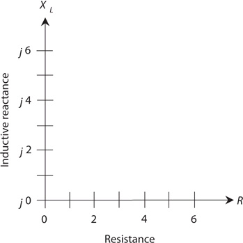
13-5 The RXL quarter-plane for inductive reactance (XL) and resistance (R).
What Are Those Little j’s For?
You’re bound to wonder what the lowercase italic letters j represent in front of all the reactance numbers in Fig. 13-5. Engineers use the symbol j to represent a mathematical quantity called the unit imaginary number. It’s the positive square root of −1. (If you didn’t already know that negative numbers can have square roots, you do now!) Electrical engineers call the positive square root of −1 the j operator. When we multiply j by itself over and over, we get the following four-way repeating sequence of quantities:
j × j = −1
j × j × j = −j
j × j × j × j = 1
j × j × j × j × j = j
j × j × j × j × j × j = −1
j × j × j × j × j × j × j = −j
j × j × j × j × j × j × j × j = 1
j × j × j × j × j × j × j × j × j = j
j × j × j × j × j × j × j × j × j × j = −1
↓
and so on, forever
When we multiply j by an ordinary number (that is, a real number), such as 2 or ![]() or 7.764958, we get an imaginary number. All of the points on the vertical scale in Fig. 13-5 represent imaginary numbers. When we add an imaginary number to a real number, we get a complex number. All of the points in the entire quarter-plane of Fig. 13-5 represent complex numbers.
or 7.764958, we get an imaginary number. All of the points on the vertical scale in Fig. 13-5 represent imaginary numbers. When we add an imaginary number to a real number, we get a complex number. All of the points in the entire quarter-plane of Fig. 13-5 represent complex numbers.
Complex Impedance
Each point on the RXL quarter-plane corresponds to a unique complex-number impedance (or simply complex impedance). Conversely, each complex impedance value corresponds to a unique point on the quarter-plane. We express a complete impedance value Z, containing resistance and inductive reactance, on the RXL quarter-plane in the form
Z = R + jXL
where R represents the resistance (in ohms) and XL represents the inductive reactance (also in ohms).
Some RXL Examples
Suppose that we have a pure resistance, say R = 5 ohms. In this case, the complex impedance equals Z = 5 + j0. We can plot it at the point (5, j0) on the RXL quarter-plane. If we have a pure inductive reactance, such as XL = 3 ohms, then the complex impedance equals Z = 0 + j3, and its point belongs at (0, j3) on the RXL quarter-plane. Engineers sometimes incorporate both resistance and inductive reactance into electronic circuit designs. Then we encounter complex impedance values, such as Z = 2 + j3 or Z = 4 + j1.5. Figure 13-6 shows graphical representations of the four complex impedances mentioned in this paragraph.

13-6 Four points in the RXL quarter-plane.
Approaching the RXL Extremes
All practical coils have some resistance because no real-world wire conducts current perfectly. All resistors have a tiny bit of inductive reactance; all electrical components have wires called leads at each end, and any length of wire (even a straight one) exhibits some inductance. Therefore, in an AC circuit, we’ll never encounter a mathematically perfect pure resistance, such as 5 + j0, or a mathematically perfect pure reactance, such as 0 + j3. We can approach these ideals, but we can never actually attain them (except in quiz and test problems).
How RXL Points Move
Always remember that the values for XL represent reactances (expressed in ohms), and not inductances (expressed in henrys). In an RXL circuit, the reactance varies with the AC frequency, even if the inductance value never changes at all. Changing the frequency produces the graphical effect of making the points move in the RXL quarter-plane. The points go vertically upward as the AC frequency increases, and downward as the AC frequency decreases. If the AC frequency goes all the way down to zero, thereby resulting in DC, the inductive reactance vanishes, and we’re left with only a little bit of resistance, representing the DC ohmic loss in the inductor.
Some RXL Impedance Vectors
Engineers sometimes represent points in the RXL quarter-plane as vectors. Expressing a point in the RXL quarter-plane as a vector gives that point a unique magnitude and a unique direction. Figure 13-6 shows four different points, each one represented by a certain distance to the right of the origin point (0, j0) that corresponds to the complex number 0 + j0, and a certain distance upward from the origin. The first number in each complex sum represents the resistance R, and the second number represents the inductive reactance XL. The RXL combination constitutes a two-dimensional quantity. We can’t define RXL combinations as single numbers (scalar quantities) because any given RXL combination possesses two quantities that can vary independently.
You can depict points, such as those shown in Fig. 13-6, by drawing straight rays from the origin out to those points. Then you can think of the rays instead of the points, with each ray having a certain length, or magnitude, and a certain direction, or angle counterclockwise from the resistance axis. These rays constitute complex impedance vectors (Fig. 13-7). When you think of complex impedances as vectors instead of mere points, you take advantage of a mathematical tool that can help you evaluate how AC circuits work under various conditions.

13-7 Four vectors in the RXL quarter-plane, corresponding to the points shown in Fig. 13-6.
Current Lags Voltage
When we place an AC voltage source across an inductor and then power up the source so that the instantaneous voltage starts to increase (either positive or negative) from zero, it takes a fraction of a cycle for the current to follow. Later in the AC wave cycle, when the voltage starts decreasing from its maximum peak (either positive or negative), it again takes a fraction of a cycle for the current to follow. The instantaneous current can’t quite keep up with the instantaneous voltage, as it does in a pure resistance, so we observe that in a circuit containing inductive reactance, the current lags (follows behind) the voltage. In some situations, this lag constitutes only a tiny fraction of an AC cycle, but it can range all the way up to ¼ of a cycle (90° of phase).
Pure Inductive Reactance
Suppose that we place an AC voltage source across a coil of wire made from an excellent conductor such as copper. Then we adjust the frequency of the AC source to a value high enough so that the inductive reactance XL greatly exceeds the resistance R (by a factor of millions, say). In this situation, the coil acts as an essentially pure inductive reactance, and the current lags ¼ of a cycle (90°) behind the voltage for all intents and purposes, as shown in Fig. 13-8.

13-8 In a pure inductive reactance, the current lags the voltage by 90°.
At low AC frequencies, we need a gigantic inductance if we want the current lag to approach 90°. As the AC frequency increases, we can get away with smaller inductances. If we could find some wire that had no resistance whatsoever, and if we wound a coil with this wire, then the current would lag the voltage by exactly 90°, regardless of the AC frequency, and regardless of the coil size. In that case, we’d have an ideal inductor or a pure inductive reactance. No such thing exists in the “real world,” but when the value of XL greatly exceeds the value of R, the vector in the RXL quarter-plane points almost exactly straight up along the XL axis. The vector subtends an angle of just about 90° from the R axis.
Inductive Reactance with Resistance
When the resistance in a resistance-inductance (RL) circuit is significant compared with the inductive reactance, the current lags the voltage by something less than 90°, as shown in the example of Fig. 13-9. If R is small compared with XL, the current lag equals almost 90°, but as R gets larger relative to XL, the lag decreases.

13-9 In a circuit with inductive reactance and resistance, the current lags the voltage by less than 90°.
The value of R in an RL circuit can increase relative to XL if we deliberately place a pure resistance in series with the inductance. It can also happen because the AC frequency gets so low that XL decreases until it reaches values comparable to the loss resistance R in the coil winding. In either case, we can schematically represent the circuit as an inductor in series with a resistor (Fig. 13-10).

13-10 Schematic representation of a circuit containing resistance and inductive reactance.
If we know the values of XL and R, we can find the angle of lag, also called the RL phase angle (or simply the phase angle if we know that we’re dealing with resistance and inductance), by plotting the point R + jXL on the RXL quarter-plane, drawing the vector from the origin out to that point, and then measuring the angle of the vector, counterclockwise from the resistance axis. We can use a protractor to measure this angle, or we can compute its value using trigonometry.
Actually, we don’t have to know the actual values of XL and R in order to find the angle of lag. All we need to know is their ratio. For example, if XL = 5 ohms and R = 3 ohms, we get the same phase angle as we do if XL = 50 ohms and R = 30 ohms, or if XL = 200 ohms and R = 120 ohms. The angle of lag turns out the same for any values of XL and R in the ratio 5:3.
Pure Resistance
As the resistance in an RL circuit becomes large with respect to the inductive reactance, the angle of lag gets small. The same thing happens if the inductive reactance gets small compared with the resistance. When R exceeds XL by a large factor, the vector in the RXL quarter-plane lies almost on the R axis, going “east,” or to the right. The phase angle in this case is close to 0°. The current flows nearly in phase with the voltage fluctuations. In a pure resistance with no inductance whatsoever, the current would follow along exactly in phase with the voltage, as shown in Fig. 13-11. A pure resistance doesn’t store and release energy as an inductive circuit does. It acquires and relinquishes all of its energy immediately, so no current lag occurs.

13-11 In a circuit with pure resistance (no reactance), the current tracks right along in phase with the voltage.
How Much Lag?
If you know the ratio of the inductive reactance to the resistance (XL/R) in an RL circuit, then you can find the phase angle. Of course, you can also find the phase angle if you know the actual values of XL and R.
Pictorial Method
You can draw an RXL quarter-plane on a piece of paper and then use a ruler and a protractor to find a phase angle in most RL situations. First, using the ruler and a sharp pencil, draw a straight line a little more than 100 mm long, going from left to right. Then with the protractor, construct a line off the left end of this first line, going vertically upwards. Make this line at least 100 mm long. The horizontal line, or the one going to the right, constitutes the R axis of a coordinate system. The vertical line, or the one going upwards, forms the XL axis.
If you know the values of XL and R, divide them down or multiply them up so they’re both between 0 and 100. For example, if XL = 680 ohms and R = 840 ohms, you can divide them both by 10 to get XL = 68 and R = 84. Plot these points lightly by making hash marks on the vertical and horizontal lines you’ve drawn. The R mark in this example should lie 84 mm to the right of the origin, and the XL mark should lie 68 mm up from the origin.
Next, draw a line connecting the two hash marks, as shown in Fig. 13-12. This line will run at a slant, and will form a triangle along with the two axes. Your hash marks, and the origin of the coordinate system, form the three vertices (corner points) of a right triangle. We call the triangle “right” because one of its angles constitutes a right angle (90°). Measure the angle between the slanted line and the R axis. Extend one or both of the lines if necessary in order to get a good reading on the protractor. This angle will fall somewhere between 0° and 90°. It represents the phase angle in the RL circuit.

13-12 Pictorial method of finding phase angle in a circuit containing resistance and inductive reactance.
You can find the complex impedance vector, R + jXL, by constructing a rectangle using the origin and your two hash marks as three of the rectangle’s four vertices, and drawing new horizontal and vertical lines to complete the figure. The vector will show up as the diagonal of this rectangle (Fig. 13-13). The angle between this vector and the R axis will represent the phase angle. It should have the same measure as the angle of the slanted line relative to the R axis in Fig. 13-12.
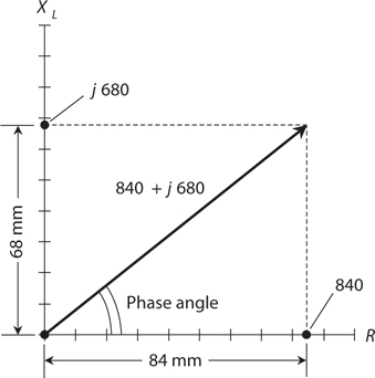
13-13 Another pictorial method of finding phase angle in a circuit containing resistance and inductive reactance. This method shows the impedance vector.
Trigonometric Method
If you have a scientific calculator that can find the Arctangent of a number (also called the inverse tangent and symbolized either as Arctan or tan−1), you can determine the phase angle more precisely than the pictorial method allows. Given the values of XL and R, the phase angle equals the Arctangent of their ratio. We symbolize phase angle as a variable with the lowercase Greek letter phi (pronounced “fie” or “fee” and written ϕ). Expressed mathematically, the phase angle is
ϕ = tan−1 (XL/R)
or
ϕ = Arctan (XL/R)
With most computers, you can find a number’s Arctangent by setting the calculator program to work in the scientific mode, entering the number, hitting the key or checking the box marked “inv,” and finally hitting the “tan” key.
Problem 13-4
Suppose that the inductive reactance in an RL circuit equals 680 ohms and the resistance equals 840 ohms. What’s the phase angle?
Solution
The ratio XL/R equals 680/840. A calculator will display this quotient as something like 0.8095 followed by some more digits. Find the Arctangent of this number. You should get 38.99 and some more digits. You can round this off to 39.0°.
Problem 13-5
Suppose that an RL circuit operates at a frequency of 1.0 MHz with a resistance of 10 ohms and an inductance of 90 μH. What’s the phase angle? What does this result tell you about the nature of this RL circuit at this frequency?
First, find the inductive reactance using the formula
XL = 6.2832 fL = 6.2832 × 1.0 × 90 = 565 ohms
Then find the ratio
XL/R = 565/10 = 56.5
The phase angle equals Arctan 56.5, which, rounded to two significant figures, comes out to be 89°. Now you know that this RL circuit contains an almost pure inductive reactance because the phase angle is close to 90°. Therefore, you know that the resistance contributes little to the behavior of this RL circuit at 1.0 MHz.
Problem 13-6
What’s the phase angle for the above circuit at a frequency of 10 kHz? With that information, what can you say about the behavior of the circuit at 10 kHz?
Solution
You must calculate XL all over again for the new frequency. You can use megahertz as your unit of frequency because megahertz work in the formula with microhenrys. A frequency of 10 kHz equals 0.010 MHz. Calculating, you get
XL = 6.2832 fL = 6.2832 × 0.010 × 90 = 5.65 ohms
Calculating the ratio of inductive reactance to resistance, you get
XL/R = 5.65/10 = 0.565
The phase angle at the new frequency equals Arctan 0.565, which, rounded to two significant figures, turns out as 29°. This angle is not close to either 0° or 90°. Therefore, you know that at 10 kHz, the resistance and the inductive reactance both play significant roles in the behavior of the RL circuit.
Quiz
Refer to the text in this chapter if necessary. A good score is 18 correct. Answers are in the back of the book.
1. A coil has an inductive reactance of 120 ohms at 5.00 kHz. What’s its inductance?
(a) 19.1 mH
(b) 1.91 mH
(c) 38.2 mH
(d) 3.82 mH
2. As a coil’s inductance rises, its fixed-frequency reactance
(a) alternately increases and decreases.
(b) stays the same.
(d) decreases.
3. An inductor has XL = 700 ohms at f = 2.50 MHz. What is L?
(a) 223 μH
(b) 22.3 μH
(c) 446 μH
(d) 44.6 μH
4. In a coil having zero resistance and an AC signal applied, the phase angle is
(a) 0°.
(b) 45°.
(c) 90°.
(d) some value that depends on the signal frequency.
5. If the inductive reactance in ohms equals the resistance in ohms in an RL circuit with an AC signal applied, then the phase angle is
(a) between 0° and 45°.
(b) 45°.
(c) between 45° and 90°.
(d) some value that depends on the signal frequency.
6. In a pure resistance without inductance and with an AC signal applied, the phase angle is
(a) 0°.
(b) 45°.
(c) 90°.
(d) some value that depends on the signal frequency.
7. According to Fig. 13-14, XL/R is

13-14 Illustration for Quiz Questions 7 and 8.
(a) 17.1.
(b) 8.57.
(c) 0.233.
(d) 0.117.
8. In Fig. 13-14, the R and XL graph scale divisions differ in size, but we can determine the phase angle anyway. It’s about
(a) 6.67°.
(b) 13.1°.
(c) 83.3°.
(d) 86.7°.
9. We apply an AC signal to a coil with an adjustable “roller tap” that lets us vary the number of coil turns through which the signal passes. (Engineers call this contraption a roller inductor.) When we set the tap so that the signal current must flow through the entire coil, we obtain a certain reactance that depends on the signal frequency. As we adjust the tap so the signal current passes through fewer and fewer turns, how must we change the signal frequency to maintain constant reactance? Assume that no resistance exists in the coil itself or in the components immediately external to it.
(a) We must not change the frequency.
(b) We must increase the frequency.
(c) We must decrease the frequency.
(d) We need more information to answer this question.
10. In the situation of Question 9, what happens to the phase angle as we adjust the coil in the manner described, assuming the coil is made of perfectly conducting wire?
(a) It stays the same.
(b) It gets larger.
(c) It gets smaller.
(d) We need more information to know.
11. The points along the vertical axis in the RXL quarter-plane correspond one-to-one with values of
(a) inductance.
(b) inductive reactance.
(c) resistance.
(d) complex impedance.
12. A coil has an inductance of 50.0 mH. What’s its reactance at 5.00 kHz?
(a) 15.7 ohms
(b) 31.4 ohms
(c) 785 ohms
(d) 1.57 k
13. A 1.0-mH inductor has a reactance of 3000 ohms. What’s the frequency?
(a) We need more information to calculate it.
(b) 0.24 MHz
(c) 0.48 MHz
(d) 0.96 MHz
14. If we increase the resistance gradually from zero to unlimited values while keeping the inductive reactance constant in an RL circuit, the resulting points in the RXL quarter-plane lie along
(a) a straight ray pointing up from some point on the resistance axis.
(b) a straight ray pointing to the right from some point on the reactance axis.
(c) a straight ray ramping up and to the right from the origin.
(d) a quarter-circle centered at the origin.
15. If we gradually increase both the resistance and the reactance in an RL circuit from zero to unlimited values at constant rates, the resulting points in the RXL quarter-plane lie along
(a) a straight ray pointing up from some point on the resistance axis.
(b) a straight ray pointing to the right from some point on the reactance axis.
(c) a straight ray ramping up and to the right from the origin.
(d) a quarter-circle centered at the origin.
16. In a certain RL circuit, the ratio of the inductive reactance to the resistance starts out large and then decreases gradually to zero. The phase angle
(a) increases and approaches 90°.
(b) decreases and approaches 45°.
(c) increases and approaches 45°.
(d) decreases and approaches 0°.
17. In a certain RL circuit, the ratio of the inductive reactance to the resistance starts out at zero and gradually increases toward a limiting value of 1.732:1. The phase angle
(a) increases and approaches 30°.
(b) decreases and approaches 30°.
(c) increases and approaches 60°.
(d) decreases and approaches 60°.
18. A coil has an inductance of 100 nH at a frequency of 100 MHz. What’s the inductive reactance?
(a) We need more information to calculate it.
(b) 126 ohms
(c) 62.8 ohms
(d) 31.4 ohms
19. An RL circuit comprises a 1.25-mH inductor and a 7.50-ohm resistor. The circuit’s interconnecting wires conduct perfectly. What’s the phase angle at 1.45 kHz?
(a) 56.6°
(b) 42.3°
(c) 33.4°
(d) 21.2°
20. What happens to the phase angle if we short out the resistor in the circuit described in the previous question?
(a) It depends on the signal frequency.
(b) It depends on the signal voltage.
(c) It stays the same.
(d) None of the above