
30
CHAPTER
Arduino
ELECTRONICS HOBBYISTS HAVE BEEN USING MICROCONTROLLERS AS LONG AS THOSE DEVICES HAVE existed. But they have become extremely popular on the back of the runaway success of the Arduino microcontroller boards. Here are some of the reasons for the success of the Arduino platform:
• Built-in USB interface and programmer (no extra hardware required)
• Simple to use Integrated Development Environment (IDE) with which to write your programs
• Works with Microsoft Windows, Mac, and Linux computers
• Simple programming language
• Standard GPIO socket arrangement for the addition of plug-in “shields”
• Open-source hardware design, so you get to see the schematic diagram of the board and understand exactly how it works
The Arduino Uno/Genuino
Although there is now a wide range of different Arduino models, the “classic” Arduino model is the Arduino Uno, more specifically the Arduino Uno revision 3. This is the device that most people think of as an Arduino. After legal difficulties, the originators of the Arduino have had to change the brand name to Genuino rather than Arduino. The boards are electrically identical, but cosmetically, look slightly different. Figure 30-1 shows an Arduino Uno with key components annotated.

30-1 The Arduino Uno.
The Arduino Uno’s USB port is used when programming the Arduino, but it can also be used to communicate with the Arduino from your PC and to provide 5 V DC to the device.
The Arduino Uno actually has two microcontroller chips on the board. The main microcontroller is the ATmega328 chip fitted into an IC socket. The second microcontroller is just to the right of the USB socket. This second microcontroller has a built-in USB interface and serves the single purpose of acting as a USB interface to the ATmega328. The USB interface microcontroller has its own In-Circuit Serial Programming (ICSP) header that allows it to be programmed during manufacture.
In the top left of the board, there is a reset switch. Pressing this takes the RESET pin of the ATmega328 low, causing the microcontroller to reset.
The top side of the board has two sections of female header pins connected to the GPIO pins of the ATmega328 labeled 0 to 13. Pin 13 is actually wired to an LED built onto the board, known as the “L” LED. This is useful because it allows you to experiment with the Arduino GPIO pins as a digital output without having to attach any external components. The pins 0 and 1 double as a TTL Serial connection that is also used for communication and programming over USB, so it is best not to use pins 0 and 1 for anything else.
After pin 13, there is a ground pin (GND) and a pin labeled AREF. The AREF pin can be connected to a voltage lower than 5 V to compress the range of the analog inputs, although this feature is not often used. The Arduino Uno operates at 5 V, and so all its digital outputs will provide 5 V when HIGH.
The two unlabeled sockets to the left of AREF are the SDA and SCK pins of an I2C interface.
The ICSP header pins on the right of the board are for factory programming of the ATmega328 with the bootloader that allows all subsequent programming of the ATmega328 to take place over USB rather than over ICSP, thus avoiding the need for special programming hardware.
The ATmega328 itself is mounted in an IC socket. This allows easy replacement of the IC should it be accidentally damaged by, say, shorting out an output pin. A socket also means that you can use the Arduino to program an ATmega328 and then remove the programmed IC and install it in an electronics project without having to commit the entire Arduino to the project. You can buy ATmega328 ICs already programmed with the Arduino bootloader to replace the chip.
At the bottom right of the board, you have six pins labeled A0 to A5 that are primarily intended for use as analog inputs, although they can all also be used as digital inputs or outputs.
The final section of the socket header is mostly concerned with power. The Vin pin can be used as an alternative to the DC Power Socket or the USB connector to power the Arduino from an unregulated 7-V to 12-V input. There are also regulated 5-V and 3.3-V power supplies from the voltage regulators built onto the board, or if being powered over USB, 5 V DC from the USB socket.
To allow for projects that require accurate timing, the Arduino uses an external 16-MHz crystal to provide the frequency for the clock to the ATmega328.
Setting Up the Arduino IDE
The Arduino IDE is a program that you run on your Windows, Mac, or Linux PC that lets you type in your program and then upload it to your Arduino board over USB. To install the latest version of the Arduino IDE, follow the instructions on the following website:
https://www.arduino.cc/en/Main/Software
When you have the software installed, run the Arduino IDE; then from the “File” menu, select the option “Examples,” “01 Basic,” and then “Blink,” and you should see a window that looks something like Figure 30-2.

30-2 The Arduino IDE.
The “Compile/Check” button compiles the Arduino C code without actually attempting to upload it to the board itself. The “Upload” button first compiles the Arduino C code and then uploads it to the Arduino over USB.
In the Arduino world, programs are called “sketches.” The next three buttons allow you to start a new sketch, open an existing sketch, or save the current sketch. Each sketch is saved as a file with the extension .iso. Each sketch file will automatically be placed inside a folder of the same name as the sketch file, but without the extension.
The top-right icon on the Arduino IDE’s toolbar opens a separate window called the “Serial Monitor” that allows you to communicate with the Arduino from your computer.
The console area of the IDE is where any error messages will appear when you try to compile a sketch or upload it to an Arduino.
Programming “Blink”
The Arduino Uno has a tiny LED attached to pin 13, labeled “L.” Your first step with an Arduino should be to make this LED blink. You may find that when you plug the LED lead into your Arduino, the “L” LED is already blinking. This happens because Arduinos are generally sold with the LED Blink sketch preinstalled. To prove that you are making the LED blink, you can make it blink faster.
When you start up the IDE and open the Blink sketch, the text of the sketch appears as shown below:

The text between /* and */ is called “comment.” It is not program code; it’s just comments to explain the sketch. Similarly, many of the lines of actual code have a // after them followed by a description of what the code does. This is also “comment” rather than program code. When using the // style of comment, the comment begins with the // and ends at the end of the line.
Edit the two lines that say: delay(1000) to read delay(200) and then save the sketch. When you come to save the sketch, the IDE will ask you to choose a new name for it because it is a read-only, built-in example. Save the sketch in a different location.
If you haven’t already done so, connect your Arduino to your PC with a USB cable. You then need to let the IDE know which USB port your Arduino is connected to, so from the Tools menu, select the “Port:” option, as shown in Figure 30-3, and select the option that has (Arduino/Genuino Uno) after it. If you have a Mac or Linux computer, then the name will be something like the one shown in Figure 30-3; if you are using Windows, then it will be called COM followed by a number.

30-3 Selecting the serial port.
You also need to tell the IDE what type of board is connected, so from the Tools menu, select “Board:” and then make sure that “Arduino/Genuino Uno” is selected.
Click on the upload button, and after the sketch has compiled, you should see the LEDs labeled TX and RX flicker while the sketch is uploaded into the flash memory of the ATmega328. This should take only a few seconds, after which the “L” LED should blink fairly fast.
Programming Fundamentals
Before taking apart the Blink sketch and adding some bells and whistles, let’s explore the fundamental concepts of programming.
A program, or in Arduino terminology a “sketch,” is a text file that contains a series of commands to be executed by the computer. In the case of the Arduino, these commands are in a programming language called C.
The commands will run (or “be executed”) in order, one after the other. A microcontroller can do only one thing at a time. For example the lines below will be executed one after the other to make the LED blink.

These commands are pretty self-explanatory, or if nothing else, explained by the comments that follow them. Note that the comment, “wait for a second,” is now wrong because we changed the delay. It should now say, “wait for 200 milliseconds (![]() of a second).”
of a second).”
There is a little more to the structure of this sketch that we will come to in the next section. But for now, the important thing to understand is that these programming commands will be executed in turn, one after the other.
In fact, it is not the text of the above program that is copied into the flash memory of the ATmega328 microcontroller, but rather the compiled version of this code. In other words, the Arduino IDE “compiles” the text that we typed into a compact machine code form that is then copied into the flash memory of the ATmega328 by the bootloader program on the ATmega328.
Setup and Loop
If you strip away the comments from the Blink example, you are left with the following lines of actual program code.

You can see that the code is divided into two blocks or “functions.” The first block starts with the line void setup { and the end of setup is marked by a }. In this case, there is just a single line between { and } that specifies that pin 13 should be set to be an output. But in other situations, there may be multiple lines of code in setup. The setup function runs once when the Arduino resets.
The second function loop will be run over and over. As soon as it finishes the last line between its { and }, it will start over with the first line. Notice how each of the lines of code within loop ends in a semicolon.
The first line inside loop uses the Arduino command digitalWrite to set pin 13 high. The next line delay instructs the Arduino processor to do nothing for 200 milliseconds or ![]() of a second. The next two lines set pin 13 low and then delay for another 200 milliseconds before the cycle starts again.
of a second. The next two lines set pin 13 low and then delay for another 200 milliseconds before the cycle starts again.
Variables and Constants
One of the most important ideas in programming is that of variables. A variable is a way of giving a name to a value. For example, the Blink sketch makes pin 13 toggle on and off, but if you wanted to use pin 10 instead, you would have to change every occurrence of “13” to “10” (three places) in the sketch. That’s not so bad in this sketch, but in a more complicated sketch, there might be lots of places where the pin number would need to be replaced, and missing one of them when making a change to the program could result in a bug that takes awhile to track down and fix.
To avoid problems like this, it is a good idea to use a variable to give the pin a name. This has the added advantage that rather than just appearing as a number that could mean anything, the pin now has a logical name that will tell someone looking at the code what it is for. In the code below, Blink has been improved by the addition of a variable to define the LED pin. The changes are highlighted in bold. Because typing in code is tedious and error prone, all the example sketches are available as a download from the GitHub page for the book at the website
https://github.com/simonmonk/tyee6
To download them, click on the “Download ZIP” button on the GitHub page. Extract the ZIP file to some convenient location. Each listing in this chapter has a comment at the top that identifies the sketch file in the downloads.

You could take this a stage further and use a variable for the delay value like this:

Variable names must be a single word (no spaces), and by convention, they start with a lowercase letter and use an uppercase letter to separate the different parts of the variable name so that the variable name can be usefully descriptive. In this example, the most logical name for the variable (ignoring all syntax rules and conventions for a moment) would be LED pin, but we are discouraged from starting the variable name with an uppercase letter, and we cannot have a space in the variable name. So we end up with a variable name of ledPin that satisfies the requirements of starting with a lowercase letter and being all one word. The uppercase P of Pin helps us to read the variable name.
Variables are defined right at the start of the program before setup. The word int is short for integer and specifies that the variable will contain a whole number. Later on we will meet other types of variables.
In the example above, once ledPin and blinkDelay are defined, there are no instructions later on in the program code that would change them. This means that they can be called constants. You can, optionally, tell the Arduino compiler that these variables are constants by prefixing them with the word const, as shown below:
const int ledPin = 13;
const int blinkDelay = 200;
The code will work whether you insert const or not, but if you do include const, it tells someone reading the code that the variable isn’t going to change later in the program, and it also allows the compiler to make slightly more efficient and compact code, saving you a few bytes of program size and RAM usage while the program runs.
The Serial Monitor
It can sometimes be a little difficult to know what the Arduino is doing. Yes, it can blink its built-in LED, but apart from that, if you have a problem with the software, it can be tricky to work out just what is going wrong. The same USB interface that allows you to upload a sketch from your computer to your Arduino can also be used to allow the Arduino to communicate with your computer and provide valuable feedback on the value of variables and what the program is doing.
To try out the Serial Monitor, modify your Blink sketch so that it appears as below.

The line that has been added to setup starts serial communication with the Arduino IDE running on your computer at the baud rate specified. A baud rate of 9600 is the default. You can change this to a higher or lower value, but you will have to also change the drop-down list on the Serial Monitor to match the value that you use in the sketch.
Now, inside the loop function, two new lines have been added that send a text message of on and off over the serial connection to the Serial Monitor.
Upload the sketch to your Arduino, and you should find that it behaves just like it did before you modified it. However, if you click on the Serial Monitor icon on the Arduino IDE, then the Serial Monitor window will open, as shown in Figure 30-4.

30-4 The Serial Monitor.
Each time the LED is turned on and off, you will see the message on or off appear in the Serial Monitor.
The values on and off inside the Serial.println commands are called strings. They are the C language’s way of representing text. If you are from a conventional programming background, then you are probably familiar with the concept of strings and use them extensively in your programming. Strings are not commonly used when writing programs for an Arduino, as an Arduino is often used in applications that do not have any means of displaying text. The exceptions to this are situations in which the Arduino is communicating with a device like your PC that does have a means of displaying text, or when you have attached display hardware to the Arduino.
Ifs
As a program runs, the normal sequence of events is to run one command after the other. However, sometimes you will need to run only some of the commands if a condition is true. For example, you might want to run only certain commands when a switch, connected to a digital input, has been pressed. Another example might be that you want to run the command to turn a digital output on only if the temperature, measured using a temperature sensor, is greater than a certain value. The mechanism for doing this is to use the C if command. Assuming that you already have a variable called temperature that contains the temperature, you could write:
if (temperature > 90) {
Serial.println(“Its hot!”);
}
Don’t worry for now where temperature gets its value from. The important point is the structure of the if command. After the word if, there is an expression in parentheses called the “condition,” and in this case, the condition is that the value in the variable temperature is greater than (>) 90. There then follows an { to indicate the start of a block of code. All the lines of code between this { and the corresponding } will be run only if the temperature indeed exceeds 90. The line Serial.println(“Its hot!”); is tabbed right to show that it belongs to the if command.
Iteration
Another common departure from simply executing a series of commands one after the other is to repeat those commands a number of times. Although the loop function in an Arduino sketch will repeat the commands it contains indefinitely, sometimes you need more control over how many times some lines of code are executed.
The main C language command for repeating things a number of times is the for command. The following sketch uses a for command to send the numbers 1 to 10 to the Serial Monitor.

Because we want the Arduino to count to 10 only once, the for loop is in setup. If we wanted the sketch to count to 10 over and over, then we would move the three lines of the for loop to the currently empty loop function so that the sketch looked like this:

The parenthesized expression after the word for contains three little snippets of code separated by semicolons. The first defines a counter variable called i, and the second section is the condition for staying in the loop. In this case, that means that the code will stay in the loop as long as i is less than or equal to (<=) 10. The final section (i++) means that 1 will be added to the value of i each time around the loop. The lines of code in between the { and } of the for loop will be run repeatedly until i is no longer less than or equal to 10.
The end result of this process is that the numbers between 1 and 10 get displayed on the Serial Monitor, as shown in Fig. 30-5.

30-5 The Serial Monitor output counting to 10.
There is a second type of loop command in C called a while loop that you will find useful from time to time.
The while command looks rather like an if command at first glance, but rather than just doing the things inside its { and } if the condition is true, it repeatedly executes the commands inside the { and } while the condition is true, stopping only when the condition is not true. At this point, the program continues to run the lines of code (if there are any) after the while loop.
If you rewrite the for example above to use while it would look like this:

The variable i is now defined before the loop starts.
Functions
Functions are named blocks of code. Every sketch has to contain a setup and a loop function, but you can also define your own functions. This tends to happen if there are some lines of code that you want to use in several places in your sketch. Rather than repeat them in the code, you define them as a function. Writing you own functions helps to make your programs easier to understand. In the following example sketch, there is a user-defined function called blink that makes the “L” LED pin 13 blink 10 times.

If you were to run this sketch, then the LED would not actually blink at all. That is because, although you have defined the blink function saying what the code must do and giving it a name, nowhere in the sketch do you actually “call” the function, telling it to run.
This separation of defining a function versus running a function is a very important distinction. In defining the function, we have created a named piece of code that knows how to “blink,” but nowhere have we actually told it to go ahead and do some blinking. It’s a bit like giving someone written instructions for making a cup of coffee but not actually telling them to go ahead and make a cup.
To fix this so that you actually get some blinking of the LED, you can put the line highlighted in bold into setup.

It does not matter where in the sketch you define the function, although it is most common to put your own functions after setup and loop. To execute or “call” the blink function, use the name of the function followed by ().
The current blink function is pretty inflexible: it can blink only 10 times, it always blinks ledPin, and the fixed delay value means it can only blink at one speed. You can make this function much more flexible and general purpose by “parameterizing” the function so it reads a

The changes are highlighted in bold. The first change is that the call to blink inside setup now has three things in the parentheses separated by commas. These are called parameters and will be “passed to” the function when it is called. The first is the pin to blink (in this case ledPin). The second is the number of times to flash, and the last is the delay period between turning the pin on and off.
The parameters inside the function are called local variables because they apply only inside the function. So when the function is called and the first parameter supplied is ledPin, the value of ledPin will be transferred to the local variable pin inside the function. Such local variables are accessible only within the function itself, whereas the other variables that we have met so far, such as ledPin, are called global variables because they are accessible throughout the sketch.
Data Types
A variable of type int in Arduino C uses two bytes of data. The type int is used for most variables. An exception is when the int range of –32768 to 32767 is not enough because you want to represent a number greater than 32767 or less than –32768, in which case a long using four bytes of data will give you big numbers.
Another situation in which an int won’t work arises when you want to represent real numbers that have digits after the decimal place. The float data type uses the binary equivalent of scientific notation. That is, the number is split into a mantissa and exponent. This gives an enormous range of values but limited precision.
Using 0.0 rather than just 0 helps to emphasize that the number is a real number and not just an integer. Table 30-1 breaks down the data types available.
Table 30-1. Data Types in Arduino C

So far our variables have all been ints and declared like
int x = 0;
Setting the initial value for the variable by following the declaration with = and then a value is optional, but considered good practice, as it removes any ambiguity about the value of the variable.
To declare a float you write something like
float x = 0.0;
Generally speaking, when performing calculations that involve a mixture of different types (say ints and floats), the compiler does a pretty good job of automatically converting types, as you would expect. For example, the following code would produce the expected result of 25,000,000.00:

The dangerous situations in which you may not get the result you expect arise when the combined number gets too big for the int data type, for example:

In this case, you would expect result to be 250, or 250,000/1000. However, if you run this sketch, the result will actually be –12. That happens because the first step of the calculation is to multiply 500 by 500, which gives a result of 250,000, which is above the limit for an int. In C, once the number exceeds the limit, the value “wraps-around” to negative numbers, giving meaningless results like the one here. If you try changing x and y to be longs the result will be as expected.
In summary, whenever you are doing arithmetic, always think through the maximum values that might arise, even for intermediate values in the calculations, and use a data type that has a big enough range for them.
Interfacing with GPIO Pins
When it comes to using the Arduino’s GPIO pins, there are a number of built-in functions that you use first to define whether the pin is to act as an input or an output, and then, either to read the value of an input into the sketch or write a value to an output.
Setting the Pin Mode
Unless otherwise specified, an Arduino pin is an input without the pin’s pull-up resistor being active. The pinMode command allows you to choose whether the pin is to act as an input or output and whether the pull-up resistor should be enabled or not.
Normally the mode of a pin is set in the setup function, but you can change the mode of a pin at any time as the sketch runs.
The pinMode built-in function takes two parameters. The first is the pin whose mode is to be set, and the second is the mode. The mode must be INPUT, INPUT_PULLUP, or OUTPUT. These are constants defined in Arduino C.
Digital Read
To read the digital value of an input pin, the built-in function digitalRead is used. This takes the pin to be read as its parameter and returns a value of 0 or 1. Returning a value means that the result of reading the digital input can be assigned to a variable, as shown in the following example sketch:

The variable x is defined inside the loop function, making it a local variable accessible only within the loop function. The result of the digitalRead function call will be assigned to the variable and will be 1 if the pin is high and 0 if the pin is low. Two special constants called HIGH and LOW are defined in the Arduino code so that you can use them instead of 1 and 0 respectively.
If you wanted to make a somewhat over-engineered light switch, you could attach a switch to pin 7 of the Arduino, and then install the following sketch to turn the built-in “L” LED on when the switch is pressed.

Rather than use a variable to store the result of the digitalRead (as we did in the previous example), the digitalRead function is used directly in the condition part of the if command. To compare two things to see if they are equal, you use a double equals sign ( == ) rather than the single sign ( = ) that you use to assign a value to a variable. The condition is that the result of calling digitalRead be LOW because the input is normally HIGH due to the pull-up resistor and only goes LOW when the switch is closed.
In this case, the if statement has an else counterpart that is run if the condition is not true.
The above example could, of course, easily be made without an Arduino at all, simply by putting a switch, an LED, and a current limiting resistor in series and connected to a voltage source.
If you wanted to change things so that pressing a push switch toggled the LED between on and off, then you would need the sketch to use a variable to keep track of whether the LED was last on or off (called its state). This is what such a sketch would look like:
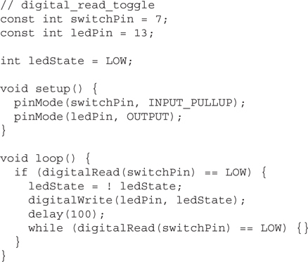
Now, when digitalRead detects that the switch button has been pressed, the variable ledState is toggled using the not (!) command. This sets ledState to be the inverse of its current setting. That is, if ledState is HIGH, it sets it LOW and vice-versa.
The digitalWrite function is then used to set the output to the new state. After that, there is a delay of 100 milliseconds that allows time for the switch contacts to settle, as they often “bounce” between high and low during the pressing of the switch.
You don’t want ledState to be immediately toggled again, so the while loop effectively waits until the switch has been released.
Digital Write
You have already used the digitalWrite command to turn the “L” LED on the Arduino board on and off. The command takes two parameters, the first being the pin to control and the second being 1 or 0 for HIGH and LOW, respectively.
The command will control the pin only if the pin has already been set to be a digital output using the pinMode command.
An Arduino pin can source or sink 40mA without any risk of damaging the ATmega328 microcontroller, which is fine for controlling an LED directly, but other devices, such as a relay or DC motor, will require some current amplification.
Because we are concerned only with turning things on and off, the amplification does not need to be linear, so a simple control with a single transistor is all that is required in most circumstances.
Figure 30-6 shows the use of an NPN bipolar transistor to provide the 50 to 100mA (or so) needed to drive the coil of a typical relay. The resistor should limit the current to less than 40mA, so 150 ohms would be ideal. A simple low-cost transistor, like the 2N3904, is suitable. The diode across the relay coil is necessary to snub (that is, suppress) any pulses of voltage resulting from driving the inductive load of the relay coil.

30-6 Controlling a relay from a digital output.
Analog Input
The Arduino has six pins labeled A0 to A5 that can provide 10-bit analog inputs. The built-in function analogRead returns a number between 0 and 1023 corresponding to the voltage at the analog input. The following sketch illustrates this, along with the math necessary to convert the reading into a voltage and print it out at the Serial Monitor.

The int reading is multiplied by 5.0 and divided by 1023.0. That is, both 5.0 and 1023.0 have a decimal point so that C knows they are floats rather than ints.
The Serial Monitor will display the voltage at pin A0 once a second, and you can actually use this scheme to measure some of the voltages on the Arduino board itself. Figure 30-7 shows a jumper wire linking A0 to GND.

30-7 An Arduino measuring its own voltages.
While this is in place, the readings should be 0 V. Change the jumper wire so that it now links A0 and the “3-V” pin. The Serial Monitor should report a voltage of around 3.3 V. Finally connect A0 to the Arduino’s “5-V” pin. Figure 30-8 shows the output of the Serial Monitor.

30-8 The Serial Monitor reporting analog readings.
Although you need to be careful not to exceed the maximum input voltage to an analog input of 5 V, you can, of course, use a pair of resistors as a voltage divider, if you need to measure higher voltages.
Analog Write
An Arduino Uno does not have true analog outputs, but rather uses pulse width modulation (PWM) as described in Chap. 29. Only the pins on an Arduino Uno marked with a ~ (3, 5, 6, 9, 10, and 11) can provide hardware supported PWM.
The command to set the duty cycle of such an output is the analogWrite command. This takes two parameters: the pin to control and the duty cycle as an int between 0 and 255. A value of 0 means the duty cycle will be 0 and the output will be fully off. A value of 255 and it will be fully on. In fact it’s just like digitalWrite except that instead of the value being 0 or 1 (LOW or HIGH) the value is between 0 and 255.
To illustrate, we can use an Arduino with a potentiometer attached to control the brightness of an LED, as shown in Fig. 30-9.

30-9 Controlling LED brightness with a potentiometer.
The sketch for this project simply takes the analog reading from the potentiometer (0 to 1023) and divides it by 4 to put it in the range 0 to 255 needed by analogWrite.

As you turn the potentiometer knob, the apparent brightness of the LED will increase as the duration of the pulses arriving at it increases. This way of controlling the apparent brightness of an LED actually works much better than controlling the voltage to the LED because, until the voltage reaches the working forward voltage of the LED (typically at least 1.6 V), the LED will not emit any light at all.
The Arduino C Library
There are a large number of commands available in the Arduino library, some of which you have already met. The most commonly used commands are listed in Table 30-2. For a full reference to all the Arduino commands, see the official Arduino documentation at the website
Table 30-2. Arduino Library Functions


Libraries
The Arduino IDE uses the concept of libraries to organize code that you might want to use in your sketches. These libraries contain program code that others have written and shared. This makes it easier to interface with certain types of hardware.
For example, the Arduino IDE comes supplied with a load of libraries pre-installed that you can make use of. It is a convention that libraries should include some example sketches that will get you started quickly when using the libraries. You can get an idea of the libraries included with the Arduino IDE from the “File” and then the “Examples” menu (see Fig. 30-10).
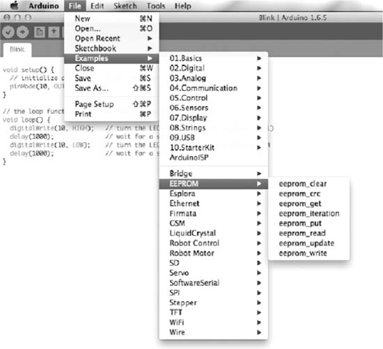
30-10 Library example sketches.
The top half of the example sketches list is not related to libraries, but below the line, all the sketches are contributed from libraries. For example, to store values persistently so that they are not lost when the Arduino is reset, you can use the EEPROM library. The “eeprom_clear” sketch is shown below with some of the comments removed for brevity.

To show the Arduino IDE that a library is required the #include command is used, followed by the name of the library’s header file. The best way to get the command right for your own sketch is just to copy it from one of the example sketches.
Other libraries that are included with the IDE are for network programming with network hardware (Ethernet), liquid-crystal displays (LCDs), reading and writing SD cards (SD) controlling servomotors (Servo), and stepper motors (Stepper).
If you have a piece of hardware that you want to control from your Arduino, then chances are there will already be a library for it included in the Arduino IDE, or there will be a library written by someone else that you can install in your Arduino IDE.
The Arduino community is very good at creating and sharing libraries. In the spirit of open-source cooperation, libraries are almost always provided free of charge and without any kind of licensing restrictions on their use. When you find a library that you want to use, it will be in the form of a ZIP file. Download the ZIP file, and then from the Arduino IDE, select the menu option “Sketch,” then “Include Library,” and then “Add ZIP Library,” and navigate to the ZIP file you just downloaded. This will install the library, and if you now look at the menu option “File” and then “Examples,” you should see a new set of examples for the library you just installed.
Special Purpose Arduinos
The Arduino Uno is by far the most commonly used Arduino; however, there are other models of Arduino that are better suited to some situations. Some of these are official Arduino boards, and others are made by third parties and use the Arduino IDE or a different IDE, but the same Arduino C language.
There are many Arduino and Arduino-compatible boards. New boards are being developed all the time, so rather than attempt a comprehensive survey, let’s focus on three representative Arduino boards.
The Arduino Pro Mini
The Arduino Uno has a lot of components and features. This can make it a little wasteful to embed an Arduino Uno into a project. For example, the Arduino has a built-in USB interface, and if you need this only while programming the board, it is unnecessary to have that USB interface permanently attached to your project.
The Arduino Pro Mini (Fig. 30-11) separates the USB interface from the rest of the Arduino so that the Arduino itself is smaller and lower-cost. This makes it more reasonable to embed an Arduino permanently into a project once you have perfected it. If you need to update the Arduino’s sketch, you can just reattach the USB interface and program it again.

30-11 The Arduino Pro Mini (left) and USB interface (right).
Programming an Arduino Pro Mini is just like programming an Arduino Uno. You just have to select a board type of “Arduino Pro or Pro Mini” in the “Board” section of the “Tools” menu.
Arduino Due
At the other extreme, sometimes an Arduino Uno does not have enough GPIO pins or is not fast enough for some demanding task. The Arduino Due is designed for such applications. (Fig. 30-12).

30-12 The Arduino Due.
The Due has 54 GPIO pins, although these operate at 3.3 V rather than the 5 V of an Arduino Uno. Besides having more pins, the Due also has a much faster processor (80-MHz clock) and a 32-bit architecture. You can find full specifications for the board at the website
https://www.arduino.cc/en/Main/ArduinoBoardDue
Arduino Particle Photon
One of the more interesting unofficial Arduino-type boards is the Photon (Fig. 30-13). This board looks similar to the Arduino Pro Mini, but the big difference is that it has built-in Wi-Fi hardware making it ideal for Internet of Things (IoT) projects.

30-13 The Arduino Particle Photon.
The board connects to your home Wi-Fi network using a smartphone app for first-time configuration. After that, you do not need any physical connection to the Photon to program it, but rather you program it over the Internet using a cloud service provided by Particle.
The Particle IDE (Fig. 30-14) looks rather like the Arduino IDE, and the language you use is the same as Arduino C with a few extensions to make network communication easier.

30-14 The Arduino Particle IDE
Shields
The Arduino header sockets can be used to attach so-called shields, which stack on top of the Arduino and are available for all sorts of purposes. An Internet search will find you no end of different shields for all sorts of purposes, including:
• Motor control
• Relays
• Ethernet and Wi-Fi
• Various types of display
• Sensors
Shields often have an accompanying Arduino library that makes them easy to use.
Quiz
Refer to the text in this chapter if necessary. A good score is 18 correct. Answers are in the back of the book.
1. The Arduino Uno has two microcontroller chips because
(a) that way it can perform twice as fast.
(b) one of the microcontroller chips is dedicated to providing a USB interface.
(c) one of the microcontroller chips provides a video interface.
(d) None of the above
2. The “L” LED of the Arduino Uno is connected to digital pin
(a) 10.
(b) 11.
(c) 12.
(d) 13.
3. The Arduino Uno clock frequency is
(a) 4 MHz.
(b) 8 MHz.
(c) 16 MHz.
(d) 20 MHz.
4. The Arduino Uno has regulated voltage outputs of
(a) 3.3 V and 5 V.
(b) 3.3 V only.
(c) 5 V only.
(d) None of the above
5. An Arduino can be powered
(a) only through its USB port.
(b) through its USB port or the DC barrel jack socket.
(c) through its DC barrel jack socket or “Vin” pin.
(d) through its USB port or the DC barrel jack socket or the “Vin” pin.
6. To use the Arduino IDE, you need a PC running
(a) Windows.
(b) Linux.
(c) Mac OS X.
(d) Any of the above
7. The USB interface of an Arduino can be used to
(a) program the Arduino.
(b) allow communication between the Arduino and your PC.
(c) power the Arduino.
(d) All of the above
8. The Arduino’s six pins labeled A0 to A5 can be used
(a) only as analog inputs.
(b) as analog inputs or analog outputs.
(c) as analog or digital inputs.
(d) as analog inputs, digital inputs, or digital outputs.
9. The Arduino delay function pauses execution in time units of
(a) seconds.
(b) milliseconds.
(c) microseconds.
(d) clock cycles.
10. Why would the “L” LED not turn on in the following sketch?

(a) Because pin 13 is not set to be an output
(b) Because the “L” LED is not connected to pin 13
(c) Because there is nothing in the loop function
(d) Because pin 13 is not usable as an output
11. In the context of programming, a variable is
(a) a numeric value such as 123.
(b) a way of giving a name to a value so that you can refer to that value by name and later change it if you want to.
(c) a named value that cannot subsequently be changed by the program.
(d) None of the above
12. A constant
(a) is a variable that cannot be changed while the program is running.
(b) is something known with certainty about what the program should do.
(c) is the same thing as a variable.
(d) uses more memory than a variable.
13. A “Sketch” is
(a) a rough design on paper for how your program is to work.
(b) a schematic for the electronic components that you are planning to connect to an Arduino.
(c) code to be “included” into your program that provides access to specialized hardware.
(d) the Arduino terminology for a program.
14. What output would you see on the Serial Monitor after running this sketch?

(a) 0
(b) 12
(d) 9600
15. What will happen when you run the following sketch?

(a) The “L” LED will blink 200 times a second.
(b) The “L” LED will blink 5 times a second.
(c) The “L” LED will appear to be on all the time.
(d) The “L” LED will appear to be off all the time.
16. Every Arduino sketch must contain the function or functions:
(a) setup.
(b) setup and loop.
(c) loop.
(d) No functions are mandatory.
17. Which of the following statements best describes the Serial Monitor?
(a) It is a USB hardware interface on the Arduino board.
(b) It monitors network traffic on your computer.
(c) It is used for programming an Arduino.
(d) It is part of the Arduino IDE that allows communication with an Arduino over USB.
18. Which of the following for constructs will count from 5 to 10 using the variable i?
(a) for (int i = 5; i <= 10; i++)
(b) for (int j = 5; i <= 10; j++)
(c) for (int i = 5; i < 10; i++)
(d) for (int i = 1; i <= 5; i++)
19. What is the maximum positive value that you can hold in a variable of type int?
(a) 255
(b) 256
(c) 65535
(d) 32767
20. Why do you need to use a reverse-biased diode across the coils of a relay?
(a) To boost the current
(b) To boost the voltage
(c) To “snub” voltage spikes as a result of switching the current to the coil
(d) None of the above