
31
CHAPTER
Transducers, Sensors, Location, and Navigation
IN THIS CHAPTER, YOU’LL LEARN ABOUT ELECTRONIC DEVICES THAT CONVERT ENERGY FROM ONE form to another, devices that can detect phenomena and measure their intensity, systems that can help you determine your location (or the location of some other object), and devices that facilitate navigation for vessels, such as ships, aircraft, and robots.
Wave Transducers
In electronics, wave transducers convert AC or DC into acoustic or electromagnetic (EM) waves. They can also convert these waves into AC or DC signals.
Dynamic Transducer for Sound
A dynamic transducer comprises a coil and magnet that translates mechanical vibration into varying electrical current or vice-versa. The most common examples are the dynamic microphone and the dynamic speaker.
Figure 31-1 is a functional diagram of a dynamic transducer. A diaphragm is attached to a coil that can move back and forth rapidly along its axis. A permanent magnet rests inside the coil. Sound waves cause the diaphragm and coil to move together, producing fluctuations in the magnetic field within the coil. As a result, audio AC flows in the coil, having the same waveform as the sound that strikes the diaphragm.

31-1 Functional diagram of a dynamic sound transducer.
If we apply an audio signal to the coil, the AC in the wire generates a magnetic field that produces forces on the coil. These forces cause the coil to move, pushing the diaphragm back and forth to create acoustic waves in the surrounding air.
Electrostatic Transducer for Sound
An electrostatic transducer takes advantage of the forces produced by electric fields. Two metal plates, one flexible and the other rigid, are placed parallel to each other and close together, as shown in Fig. 31-2.

31-2 Functional diagram of an electrostatic sound transducer.
In an electrostatic pickup, incoming sound waves vibrate the flexible plate, producing small, rapid changes in the spacing, and therefore, the capacitance, between the plates. We apply a constant DC voltage between the plates. As the plate-to-plate capacitance varies, the electric field intensity between them fluctuates, causing variations in the current through the transformer primary winding. Audio signals appear across the secondary winding.
In an electrostatic emitter, fluctuating currents in the transformer produce changes in the voltage between the plates. This AC voltage results in electrostatic field variations, producing forces that push and pull the flexible plate in and out. The motion of the flexible plate produces sound waves in the air.
We can use electrostatic transducers in most applications in which dynamic transducers will work. Advantages of electrostatic transducers include light weight and good sensitivity. The relative absence of magnetic fields can also constitute an asset in certain situations.
Piezoelectric Transducer for Sound and Ultrasound
Figure 31-3 shows a piezoelectric transducer that consists of a slab-like crystal of quartz or ceramic material sandwiched between two metal plates. Piezoelectric transducers can function at higher frequencies than dynamic or electrostatic transducers can, so piezoelectric transducers are favored in ultrasonic applications such as intrusion detectors.

31-3 Functional diagram of a piezoelectric transducer for sound and ultrasound.
When acoustic waves strike one or both of the plates, the metal vibrates. This vibration transfers to the crystal by mechanical contact. The crystal generates weak electric currents when subjected to the mechanical stress. Therefore, an AC voltage develops between the two metal plates, with a waveform identical to that of the acoustic disturbance.
If we apply an electrical audio signal to the plates, the fluctuating current causes the crystal to vibrate in sync with the current. The metal plates vibrate also, producing an acoustic disturbance in the surrounding medium.
Transducers for RF Energy
The term radio-frequency (RF) transducer is a fancy expression for an antenna. Two basic types exist: the receiving antenna and the transmitting antenna.
Transducers for IR and Visible Light
Many wireless devices transmit and receive energy in the infrared (IR) spectrum, which spans frequencies higher than those of radio waves but lower than those of visible light. Some wireless devices transmit and receive EM signals in the visible range, although we will encounter them less often than we find IR devices.
The most common IR transmitting transducer is the infrared-emitting diode (IRED). When you apply fluctuating DC to the device, it emits IR rays. The fluctuations in the current constitute modulation, causing variations in the intensity of the rays emitted by the semiconductor P-N junction. The modulated IR carries information such as which channel you want your television (TV) set to “see” or whether you want to raise or lower the volume. You can focus an IR beam using optical lenses or mirrors to collimate the rays (make them parallel) for line-of-sight transmission through clear air over distances of up to several hundred meters.
Infrared receiving transducers resemble photodiodes or photovoltaic cells. The fluctuating IR energy from the transmitter strikes the P-N junction of the receiving diode. If the receiving device is a photodiode, you apply a current to it. This current varies rapidly in accordance with the signal waveform on the IR beam from the transmitter. If the receiving device is a photovoltaic cell, it produces the fluctuating current all by itself, without the need for an external power supply. In either case, the current fluctuations are weak, and you must amplify them before sending them to the equipment (TV set, garage-door opener, oven, security system, or whatever) controlled by the wireless system.
Displacement Transducers
A displacement transducer measures a distance or angle traversed, or the distance or angle separating two points. Conversely, a displacement transducer can convert an electrical signal into mechanical movement over a certain distance or angle. A device that measures or produces movement in a straight line constitutes a linear displacement transducer. If it measures or produces movement through an angle, we call it an angular displacement transducer.
Pointing and Control Devices
A joystick can produce movement or control variable quantities in two dimensions. The device has a movable lever attached to a ball bearing within a control box. You can manipulate the lever by hand up and down, or to the right and left. Some joysticks allow you to rotate the lever for control in a third dimension. Joysticks are used in computer games, for entering coordinates into a computer, and for the remote-control of robots.
A mouse is a peripheral device commonly used with personal computers. By sliding the mouse around on a flat surface, you can position a cursor or arrow on the computer display. Push-button switches on the top of the unit actuate the computer to perform whatever function the cursor or arrow shows. These actions are called clicks.
A trackball resembles an inverted mouse, or a two-dimensional joystick without the lever. Instead of pushing the device around on a flat surface, you manipulate a ball bearing with the index finger of one hand, causing the display cursor to move vertically and horizontally. Push-button switches on a computer keyboard, or on the trackball box itself, actuate the functions.
An eraser-head pointer is a rubber button approximately five millimeters (5 mm) in diameter, usually placed in the center of a computer keyboard. You move the cursor on the display by pushing against the button. Clicking is done with button switches on the keyboard.
A touch pad is a sensitive plate approximately the size and shape of a credit card. You place your index finger on the plate and move your finger around, producing movement of the display cursor or arrow. You can do clicks just as you do with a trackball or eraser-head pointer.
Electric Motor
An electric motor converts electrical energy into angular (and in some cases linear) mechanical energy. Motors can operate from either AC or DC, and range in size from tiny devices used in microscopic robots to huge machines that pull passenger trains. You learned the basic principle of the DC motor in Chap. 8. In a motor designed to work with AC, no commutator exists. Instead, the alternations in the current keep the polarity correct at all times, so the shaft does not “lock up.” The rotational speed of an AC motor depends on the frequency of the applied AC. With 60 Hz AC, for example, the rotational speed equals 60 revolutions per second (60 r/sec) or 3600 revolutions per minute (3600 r/min). When you connect a motor to a load, the rotational force required to turn the shaft increases and the motor draws increasing power from the source.
Stepper Motor
A stepper motor turns in small increments, rather than continuously. The step angle, or extent of each turn, varies depending on the particular motor. It can range from less than 1° of arc to a quarter of a circle (90°). A stepper motor turns through its designated step angle and then stops, even if the coil current continues. When the shaft of a stepper motor has come to rest with current going through its coils, the shaft resists external rotational force; it “tries to stay in place.”
Conventional motors run at hundreds or thousands of revolutions per minute. A stepper motor usually runs at far lower speeds, almost always less than 180 r/min. A stepper motor has the most turning power when operated at its slowest speeds, and the least turning power when operated at its highest speeds.
When we supply current pulses to a stepper motor at a constant frequency, the shaft rotates in increments, one step for each pulse. In this way, the device can maintain a precise speed. Because of the braking effect, this speed holds constant over a wide range of mechanical turning resistances. Stepper motors work well in applications requiring point-to-point motion. Specialized robots can perform intricate tasks with the help of microcomputer-controlled stepper motors.
Selsyn and Synchro
A selsyn is an indicating device that shows the direction in which an object points. The selsyn consists of a transmitting unit and a receiving (or indicator) unit. As the shaft of the transmitting unit rotates, the shaft of the receiving unit, which forms part of a stepper motor, follows along exactly. Figure 31-4 shows how we can employ a selsyn to serve as a remote direction indicator for a wind vane. As the vane rotates, the indicator unit shaft moves through the same number of angular degrees as the transmitting unit shaft.
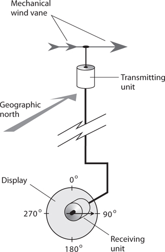
31-4 We can use a selsyn to remotely indicate the direction in which a mechanical device points.
A pair of selsyns can display the orientation of a space-communications antenna that has two separate rotators, one for the azimuth (compass bearing) and another for the elevation. The selsyn for azimuth bearings has a range of 0° to 360°. The selsyn for elevation bearings has a range of 0° to 90°.
A synchro is a two-way selsyn that can control certain mechanical devices and also display their status. Synchros work well for robotic teleoperation, or remote control. Some synchros are programmable. The operator inputs a number into a microcomputer that controls the generator unit, and the receiver unit changes position accordingly. Synchros are also used for precision control of directional communications antennas, such as the Yagi, corner reflector, or dish.
Electric Generator
An electric generator is constructed in much the same way as an AC motor, although it functions in the opposite sense. Some generators can also function as motors; we call dual-purpose devices of this type motor/generators.
A typical generator produces AC from the mechanical rotation of a coil in a strong magnetic field. Alternatively, a permanent magnet can be rotated within a coil of wire. We can drive the rotating shaft with a gasoline engine, a steam turbine, a water turbine, a wind turbine, or any other source of mechanical power. A commutator can work with a generator to produce pulsating DC output, which we can filter, if desired, to obtain pure DC to operate electronic equipment.
Small portable gasoline-powered generators, capable of delivering a few kilowatts, can be purchased in department stores or home-and-garden stores. Larger generators, which usually burn propane or methane (“natural gas”), allow homes or businesses to retain a continuous supply of electrical power during a utility disruption. The largest generators are found in power plants, and can produce many kilowatts.
Small generators can function in synchro systems. These specialized generators allow remote control of robotic devices. A generator can be used to measure the speed at which a vehicle or rolling robot moves. The shaft of the generator is connected to one of the wheels, and the generator output voltage and frequency vary directly with the angular speed of the wheel. In this case we have a tachometer.
Optical Encoder
When we use digital radios, we adjust the frequency in discrete steps, not continuously. A typical frequency increment is 10 Hz for “shortwave” radios and 200 kHz for FM broadcast radios. An optical encoder, also called an optical shaft encoder, offers an alternative to mechanical switches or gear-driven devices that wear out with time.
An optical encoder comprises two LEDs, two photodetectors, and a device called a chopping wheel. The LEDs shine on the photodetectors through the wheel. The wheel, which has alternately transparent and opaque radial bands (Fig. 31-5), is attached to a rotatable shaft and a control knob. As we rotate the knob, the light beams are interrupted. Each interruption causes the frequency to change by a specified increment.

31-5 An optical encoder uses LEDs and photodetectors to sense the direction and extent of shaft rotation.
When used for frequency control, an optical shaft encoder can sense the difference between the “frequency-up” command (clockwise shaft rotation) and the “frequency-down” command (counterclockwise shaft rotation) according to which photodetector senses each sequential beam interruption first.
Detection and Measurement
A sensor employs one or more transducers to detect or measure parameters, such as temperature, humidity, barometric pressure, pressure, texture, proximity, and the presence of certain substances.
Capacitive Pressure Sensor
Figure 31-6 portrays the functional details of a capacitive pressure sensor. Two metal plates, separated by a layer of compressible dielectric foam, create a variable capacitor that we connect in parallel with an inductor. The resulting inductance/capacitance (LC) circuit determines the frequency of an oscillator. If an object strikes or pushes against the sensor, the plate spacing momentarily decreases, causing an increase in the capacitance and, therefore, a decrease in the oscillator frequency. When the object moves away from the transducer, the foam layer springs back to its original thickness, the plates return to their original spacing, and the oscillator frequency returns to normal.

31-6 A capacitive pressure sensor. When force is applied, the spacing between the plates decreases, causing the capacitance to increase and the oscillator frequency to go down.
We can convert the output of a capacitive pressure sensor to digital data using an analog-to-digital converter (ADC). This signal can go to a microcomputer, such as a robot controller. We can mount pressure sensors in various places on a mobile robot, such as the front, back, and sides. Then, for example, physical pressure on the sensor in the front of the robot can send a signal to the controller, which tells the machine to move backward.
A capacitive pressure sensor can be fooled by massive conducting or semiconducting objects in its vicinity. If such a mass comes near the transducer, the capacitance can change even if direct mechanical contact does not occur. We call this phenomenon body capacitance. In some applications, we can tolerate body capacitance; in other situations, we can’t.
Elastomer
When we want to avoid the effects of body capacitance, we can use an elastomer device instead of a capacitive device for pressure sensing. An elastomer is a flexible substance resembling rubber or plastic that can be used to detect the presence or absence of mechanical pressure.
Figure 31-7 illustrates how we can employ an elastomer to detect and locate a pressure point. The elastomer conducts electricity fairly well, but not perfectly. It has a foam-like consistency, so that it can be compressed. Conductive plates are attached to opposite faces of the elastomer pad.

31-7 An elastomer pressure sensor detects applied force without unwanted capacitive effects.
When pressure appears at some point in the pad, the material compresses, and its electrical resistance goes down. The drop in resistance produces an increase in the current between the plates. As the applied pressure increases, the elastomer grows thinner, and the current goes up more. The current-change data can be sent to a microcomputer, such as a robot controller.
Back-Pressure Sensor
A motor produces a measurable pressure that depends on the torque (“turning force”) that we apply. A back-pressure sensor detects and measures the torque that the motor exerts at any given instant in time. The sensor produces a signal, usually a variable voltage, that increases as the torque increases. Figure 31-8 is a functional diagram of the system.

31-8 A back-pressure sensor governs the force applied by a robot arm or other mechanical device.
Robotics engineers use back-pressure sensors to limit the forces applied by robot grippers, arms, drills, hammers, or other so-called end effectors. The back voltage, or signal produced by the sensor, reduces the torque applied by the motor, preventing damage to objects that the robot handles, and also ensuring the safety of people working around the robot.
Capacitive Proximity Sensor
A capacitive proximity sensor uses an RF oscillator, a frequency detector, and a metal plate connected into the oscillator, as shown in Fig. 31-9. The resulting device takes advantage of the body capacitance effects that can confound capacitive pressure sensors. We design the oscillator so that any variation in the capacitance of the plate, with respect to the environment, causes the oscillator frequency to change. The frequency detector senses this change and transmits a signal to a microcomputer or robot controller.

31-9 A capacitive proximity sensor can detect nearby conducting or semiconducting objects.
Substances that conduct electricity to some extent (such as metal, salt water, and living tissue) are sensed more easily by capacitive transducers than are materials that do not conduct, such as dry wood, plastic, glass, or dry fabric. For this reason, capacitive proximity sensors work poorly, if at all, in environments that lack conductive objects. A machine shop would present a better venue for a robot with capacitive proximity sensing than, say, a child’s bedroom.
Photoelectric Proximity Sensor
Reflected light can help a robot “know” when it’s approaching a physical barrier. A photoelectric proximity sensor contains a light-beam generator, a photodetector, a frequency-sensitive amplifier, and a microcomputer, interconnected and operated as shown in Fig. 31-10.

31-10 A photoelectric proximity sensor. Modulation of the light beam allows the device to distinguish between sensor-generated light and background illumination.
The light beam reflects from the object, and the photodetector picks up some of the reflected light. The tone generator modulates the light beam at a certain frequency, say, 1000 Hz. The photodetector’s amplifier responds only to light modulated at that frequency. This modulation scheme prevents false imaging that could otherwise result from stray illumination from flashlights or sunlight. (Such light sources are unmodulated, and won’t actuate a sensor designed to respond only to modulated light.) As the robot approaches an object, the robot controller senses the increasing intensity of the reflected, modulated beam. The robot can then steer clear of the obstruction.
Photoelectric proximity sensing doesn’t work for objects that don’t reflect light, or for shiny objects, such as glass windows or mirrors, approached at a sharp angle. In these scenarios, none of the light beam reflects back toward the photodetector, so the object remains “invisible” to the robot.
Texture Sensor
Texture sensing is the ability of a machine to determine whether an object has a shiny surface or a rough (matte) surface. A simple texture sensor contains a laser and several light-sensitive receptors.
Figure 31-11 shows how a combination of laser (L) and sensors (S) can tell the difference between a flat shiny surface (drawing A) and a flat matte (roughened) surface (drawing B). The shiny surface, such as a flat glass mirror or flat pane of glass, reflects light at the incidence angle only. But the matte surface, such as a sheet of paper, scatters light in all directions. The shiny surface reflects the beam back entirely to the sensor in the path of the beam whose reflection angle equals its incidence angle. The matte surface reflects the beam back to all the sensors. We can program a microcomputer to tell the difference.

31-11 In texture sensing, lasers (L) and sensors (S) analyze a shiny surface (at A) and a matte surface (at B). Solid lines represent incident light; dashed lines represent reflected light.
Certain types of surfaces can confuse a texture sensor of the type portrayed in Fig. 31-11. For example, we would define a pile of small ice cubes as shiny on a microscopic scale but rough on a large scale. Depending on the diameter of the laser beam, the texture sensor might interpret such a surface as either shiny or matte. The determination can also be affected by the motion of the sensor relative to the surface. A surface interpreted as shiny when standing still relative to the sensor might be interpreted as matte when moving relative to the sensor.
Location Systems
The devices described in the previous paragraphs function best in short-range applications (with the exception of RF antennas). In this section, we’ll examine a few medium-range and long-range applications of transducers and sensors. These applications fall into the broad category of location systems.
Radar
The term radar derives from the words radio detection and ranging. Electromagnetic (EM) waves having certain frequencies reflect from various objects, especially if those objects contain metals or other electrical conductors. By ascertaining the direction(s) from which radio signals are returned, and by measuring the time it takes for a pulsed beam of EM energy to travel from the transmitter location to a target and back again, a radar set can pinpoint the geographic positions of distant objects. During the Second World War in the 1940s, military personnel put this property of radio waves to use for the purpose of locating aircraft.
In the years following the war, practical-minded experimenters discovered that radar can serve in a variety of applications, such as measurement of automobile speed (by the police), weather forecasting (rain and snow reflect radar signals), and even the mapping of planets, planetary moons, asteroids, and comets. Commercial and military aviators use radar extensively. In recent years, radar has also found uses in robot guidance systems.
A complete radar set consists of a transmitter, a directional antenna with a narrow main lobe and high gain, a receiver, and an indicator or display. The transmitter produces intense pulses of RF microwaves at short intervals. The pulses propagate outward in a sharply defined beam from the antenna, and the wavefronts strike objects at various distances. Shortly after the pulse transmission, the receiving antenna picks up the reflected signals, known as echoes. As the distance to a reflecting object (often called a target) increases, so does the delay time between pulse transmission and echo reception. The transmitting antenna rotates in a horizontal plane at constant angular speed, allowing observation in all azimuth bearings (compass directions).
A typical circular radar display comprises a CRT or LCD, equipped to show scans of azimuth and range (distance to the target). Figure 31-12 shows the basic display configuration. The observing station’s location corresponds to the center of the display. Azimuth bearings are indicated in degrees clockwise from true north, and are marked around the perimeter of the screen. The range is indicated by the radial displacement of the echo; the farther away the target, the farther from the display center the echo or blip. The radar display constitutes a dynamic set of plane polar coordinates. In Fig. 31-12, a target appears at an azimuth of about 124° (east-southeast). Its range is near the maximum for the display, known as the radar horizon.

31-12 A radar display. The light radial band shows the azimuth direction in which the microwave beam is currently transmitted and received. (Not all radar displays show this band.)
For any particular installation, the distance to the radar horizon depends on the height of the antenna above the ground, the nature of the terrain in the area, the transmitter output power and antenna gain, the receiver sensitivity, and the weather conditions in the vicinity. Airborne long-range radar can detect echoes from several hundred kilometers (km) away under ideal conditions. A low-power system with the antenna at a low height might have a radar horizon of only 50 to 70 km.
The fact that precipitation reflects radar echoes creates an ongoing nuisance to aviation personnel, but it’s invaluable for weather forecasting and observation. Radar allows aviators and meteorologists to detect and track severe thunderstorms and hurricanes. A mesocyclone, which is a severe thunderstorm likely to produce tornadoes, generates a characteristic “hook-shaped” echo on a radar display. The eyewall and rainbands surrounding the center of a hurricane show up as rings, arcs, or broken-up spirals on the display.
Some radar sets can detect changes in the frequency of the returned pulse, thereby allowing measurement of wind speeds in hurricanes and tornadoes, or the speeds and acceleration rates of approaching and receding targets. A system of this type is called Doppler radar because the frequency change results from the Doppler effect on EM waves.
Sonar
Sonar is a medium-range method of proximity sensing. The acronym derives from the words sonic navigation and ranging. The principle is simple: Bounce acoustic waves off of objects, and measure the time it takes for the echoes to return.
An elementary sonar system consists of an AC pulse generator, an acoustic emitter, an acoustic pickup, a receiver, a delay timer, and an indicating device, such as a numeric display, CRT, LCD, or pen recorder. The transmitter sends out acoustic waves through the medium, usually water or air. These waves are reflected by objects, and the echoes are picked up by the receiver. The distance to an object is determined on the basis of the echo delay, assuming that the speed of the acoustic waves in the medium is known.
Figure 31-13A shows a simple sonar system. The microcomputer can generate a computer map on the basis of sounds returned from various directions in two or three dimensions. This map can help a mobile robot or vessel navigate in its environment. However, the system can be “fooled” if the echo delay equals or exceeds the time interval between pulses, as shown in Fig. 31-13B. To overcome this conundrum, the microcomputer can instruct the pulse generator to send pulses of various frequencies in a defined, rotating sequence. The microcomputer keeps track of which echo corresponds to which pulse.

31-13 At A, a block diagram of a medium-range sonar system. At B, unexpectedly long delays can confuse a sonar system.
Acoustic waves travel faster in water than they do in the air. The amount of salt in water makes a difference in the propagation speed when sonar is used on boats (in depth finding, for example). The density of water can vary because of temperature differences as well. If the true speed of the acoustic waves is not accurately known, false readings will result. In fresh water, acoustic waves travel at about 1400 meters per second (m/s), or 4600 feet per second (ft/s). In salt water, acoustic waves travel at about 1500 m/s (4900 ft/s). In air, acoustic waves travel at approximately 335 m/s (1100 ft/s).
In the atmosphere, sonar can operate with audible sound waves, but ultrasound is often used instead. Ultrasound has a frequency too high to hear, ranging from about 20 kHz to more than 100 kHz. The most significant advantage of ultrasound is the fact that people who work around the sonar devices can’t hear the signals, and will, therefore, not experience distraction, headaches, or other ill effects from them. In addition, ultrasonic sonar is less likely than audible sonar to be confused by people talking, heavy equipment, loud music, and other common noise sources. At frequencies higher than the range of human hearing, acoustical disturbances don’t occur as often, or with as much intensity, as they do within the hearing range.
In its most advanced forms, sonar can rival vision systems (also called machine vision) as a means of mapping the environment for a mobile robot or vessel at close range. However, sonar has an outstanding limitation: All acoustic waves, including sound and ultrasound, require a material medium (usually a gas or liquid) in order to propagate. Therefore, sonar won’t work in outer space, which practically constitutes a vacuum. Another significant limitation of sonar results from the fact that acoustic waves travel far more slowly than EM waves, such as radar pulses or visible-light beams, severely limiting the practical range (or sonar horizon).
Signal Comparison
A machine or vessel can find its geographic position by comparing the signals from two fixed stations at known positions, as shown in Fig. 31-14A. By adding 180° to the bearings of the sources X and Y, the machine or vessel (small shaded rectangle) obtains its bearings as “seen” from the sources (small spheres). The machine or vessel can determine its direction and speed by taking two readings separated by a certain amount of time. In the old days, the navigators of aircraft and oceangoing vessels physically plotted diagrams resembling Fig. 31-14A on paper maps using a pen, a straight-edged ruler, and a drafting compass, a process known as triangulation. Nowadays, computers do that work, with speedier and more accurate results.

31-14 A simple direction-finding scheme (A) and an ultrasonic direction finder (B).
Figure 31-14B is a block diagram of an acoustic direction finder such as a mobile robot might employ. The receiver has a signal-strength indicator and a servo that turns a directional ultrasonic transducer. The system has two remotely located signal sources, called beacons, that operate at different frequencies. When the transducer rotates so the signal from one beacon reaches its maximum amplitude, a bearing is obtained by comparing the orientation of the transducer with some known standard such as a magnetic compass. The same is done for the other beacon. A computer determines the precise location of the robot based on this data.
Radio Direction Finding (RDF)
We can use a radio receiver, equipped with a signal-strength indicator and connected to a rotatable, directional antenna, to determine the direction from which RF signals arrive. Radio-direction-finding (RDF) equipment aboard a mobile vehicle facilitates determining the location of an RF transmitter. An RDF receiver can also serve to find one’s own position with respect to two or more RF transmitters operating on different frequencies.
At frequencies below approximately 300 MHz, an RDF receiver employs a small loop or loopstick antenna shielded against the electric component of radio waves, so it picks up only the magnetic part of the EM field. The loop rotates until a well-defined minimum, or null, occurs in the received signal strength, indicating that the axis of the loop lies along a line toward the transmitter. When we take signal-strength readings from two or more locations separated by a sufficient distance, we can pinpoint the location of the transmitter by finding the intersection point of the azimuth bearing lines on a map. A computer, obviously, can do the same.
At frequencies above approximately 300 MHz, a directional transmitting and receiving antenna, such as a Yagi, quad, dish, or helical type, gives better results than a small loop. When we use such an antenna for RDF, the azimuth bearing corresponds to a signal maximum, or peak, rather than to a signal null.
Navigational Methods
Navigation involves the use of location devices over a continuous period, thereby deriving a function of position versus time. We can use this technique to determine whether or not a vessel follows its prescribed course. We can also use navigation methods to track the paths of military targets, severe thunderstorms, and hurricanes.
Fluxgate Magnetometer
When conventional position sensors won’t function in a particular environment for a mobile robot, a fluxgate magnetometer can sometimes work. This system employs sensitive magnetic receptors and a microcomputer to detect the presence of, and changes in, an artificially generated magnetic field. The robot can navigate within a room by checking the orientation of magnetic lines of flux generated by electromagnets in the walls, floor, and ceiling.
For each point in the room, the magnetic flux lines have a unique direction and intensity, so that a one-to-one correspondence exists between the magnetic flux vector (intensity-direction composite) and the points within the robot’s operating environment. This correspondence translates into a two-variable mathematical function of every location in the room. We can program the robot controller with this function, allowing the robot to constantly determine its position to within a few millimeters.
Epipolar Navigation
Epipolar navigation works by evaluating how an image changes as viewed from a single, moving perspective. The system needs only one observation point (that is, one observer location) at any given moment in time.
Imagine that you pilot an aircraft over the ocean. The only land in sight is a small island. The on-board computer “sees” an image of the island that constantly changes shape. Figure 31-15 shows three sample sighting positions (A, B, C) and the size/shape of the island as “seen” by a machine vision system in each case. The computer has the map data, so it “knows” the true size, shape, and location of the island.

31-15 Epipolar navigation is the opto-electronic counterpart of human spatial perception.
The computer compares the shape and size of the image it “sees” at each point in time, from the vantage point of the aircraft, with the actual shape and size of the island from the map data. From this information, the computer can ascertain the aircraft’s altitude, ground speed, ground direction, geographic latitude, and geographic longitude.
Loran
The acronym loran derives from the words long-range navigation. Loran is one of the oldest electronic navigation schemes. The system employs RF pulse transmission at low and medium frequencies (typically below 2 MHz) from multiple transmitters at specific geographic locations. A computer on board an oceangoing vessel can determine the ship’s location by comparing the time difference in the arrival of the signals from two different transmitters at known locations. Based on the fact that radio waves propagate at the speed of light in free space (approximately 299,792 km/s or 186,282 mi/s), the computer can determine the distance to each transmitter, and from this data, calculate the location of the ship relative to the transmitters. In recent years, loran has been largely supplanted by the Global Positioning System (GPS).
Global Positioning System (GPS)
The Global Positioning System (GPS) comprises a network of radiolocation and radionavigation units that operate on a worldwide basis. The system employs several satellites, and allows determination of latitude, longitude, and altitude.
All GPS satellites transmit signals in the microwave part of the radio spectrum. The signals are modulated with codes that contain timing information used by the receiving apparatus to make measurements. A GPS receiver determines its location by measuring the distances to several different satellites. This task is carried out by precisely timing the signals as they travel between the satellites and the receiver. The process resembles old-fashioned navigators’ triangulation, except that it takes place in three dimensions (space) rather than in two dimensions (on the surface of the earth).
Electromagnetic waves propagate a little more slowly in the earth’s ionosphere than they do in outer space. The extent of this reduction depends on the signal frequency, the ionization density in the upper atmosphere, and the angle at which the signal beams must work their way through the ionized layers. The GPS employs dual-frequency transmission to compensate for this effect. A GPS receiver uses a computer to process the information received from the satellites, giving the user an indication of position accurate to within a few meters.
Increasingly, automobiles, trucks, and pleasure boats are sold with GPS receivers installed as standard equipment. If you’re driving your car through a remote area and you get lost, you can use GPS to locate your position. Using a cell phone, wireless Internet connection, Citizens Band (CB) radio transceiver, or amateur (“ham”) radio transceiver, you can call for help and inform authorities of your exact position, which appears on an easy-to-read map.
Quiz
Refer to the text in this chapter if necessary. A good score is at least 18 correct. Answers are in the back of the book.
1. What would a mobile robot most likely use to locate itself in a large vacant parking lot?
(a) A capacitive proximity sensor with multiple RF beacons
(b) A dynamic transducer with multiple IR beacons
(c) An optical shaft encoder with multiple visible-light beacons
(d) An acoustic direction finder with multiple ultrasonic beacons
2. At night, you can determine the location of a tornado near you using a
(a) radar set.
(b) sonar set.
(c) fluxgate magnetometer.
(d) capacitive proximity sensor.
3. Which of the following systems, if any, can use magnetic receptors and a microcomputer to sense the presence of, and detect changes in, an external magnetic field?
(a) A capacitive proximity sensor
(b) An epipolar navigator
(c) A synchro or selsyn
(d) None of the above
4. Which of the following devices would you use to control and display the compass direction toward which a dish antenna points?
(a) A fluxgate magnetometer
(b) The GPS
(c) A synchro
(d) A capacitive proximity sensor
5. An elastomer pad, considered as an object all by itself, has variable
(a) conductance.
(b) magnetic-field intensity.
(c) sensitivity to ultrasound.
(d) inductive reactance.
6. An azimuth-range radar display has a geometric configuration similar to that of
(a) an analog meter.
(b) a digital bar graph meter.
(c) an analog TV display.
(d) a polar-coordinate system.
7. You can use sonar to measure sound
(a) loudness.
(b) frequency.
(c) speed.
(d) None of the above
8. A fluxgate magnetometer allows a robot to locate itself on the basis of
(a) body capacitance with nearby objects.
(b) the orientations of external magnetic fields.
(c) the phase relationships among multiple ultrasonic beacon signals.
(d) optical delays to and from stationary reflectors.
9. Which of the following devices is not an electromechanical transducer?
(a) An electric motor
(b) An electric generator
(c) A selsyn
(d) A fluxgate magnetometer
10. At low radio frequencies, an RDF system typically employs
(a) a Yagi antenna.
(b) a small loop or loopstick antenna.
(c) a dish antenna.
(d) a half-wave dipole antenna.
11. A robot can use a back-pressure sensor to
(a) measure the intensity of visible light.
(b) regulate the torque produced by an electric drill.
(c) determine the orientation of magnetic lines of flux.
(d) regulate the output of an acoustic transducer.
12. When you apply AF voltage to the plates of an electrostatic transducer, the electric field between the plates fluctuates in intensity, causing
(a) a magnetic field that moves the coil, producing sound waves.
(b) the capacitance to vary, thereby generating a phase shift.
(c) forces that move the flexible plate, producing sound waves.
(d) the plates to charge and discharge, producing AF current.
13. Which of the following devices is a form of RF transducer?
(a) A small loop antenna
(b) A back-pressure sensor
(c) An elastomer
(d) An epipolar navigation sensor
14. In a dynamic pickup or microphone, incident sound waves cause AF current to flow in the coil as a result of
(a) the coil’s motion within a magnetic field.
(b) the coil’s motion within an electrostatic field.
(c) a DC voltage applied to the coil.
(d) changes in the capacitive reactance across the coil.
15. A motor whose shaft rotates in discrete increments (not continuously) is called
(a) an incremental motor.
(b) a stepper motor.
(c) a fractional motor.
(d) a selsyn.
16. A photoelectric proximity sensor might have trouble detecting
(a) a gray curtain.
(b) a black wall.
(c) a red ball.
(d) All of the above
17. How many simultaneous observing locations does an epipolar navigation system require?
(a) One
(b) Two
(c) Three
(d) Four
18. Which of the following devices or systems operates at the lowest frequency?
(a) A radar set
(b) The GPS
(c) A photoelectric proximity sensor
(d) A loran system
19. Which of the following devices or systems operates on the basis of fluctuating magnetic forces between physical objects?
(a) A sonar system
(b) A loran system
(c) A dynamic transducer
(d) A capacitive proximity sensor
20. You would use a piezoelectric transducer to detect
(a) magnetic fields.
(b) ultrasonic waves.
(c) microwave RF signals.
(d) torque produced by a motor.