
In this section, we show the results of joint radio-channel assignment, routing, and scheduling for optimizing an end-to-end throughput solved by our methodology for two simple scenarios, and simulation results for more general networks. All the simulations are implemented in Matlab.
5.5.1 Two Scenarios with Different Link Qualities
We consider two four-node network scenarios in Figure 5.7 with different link qualities. Suppose each node has one radio that can be operated on two orthogonal channels. The PRR is indicated on each link. For simplicity, we assume the PRR is identical under different channels in each network. We assume each node is in the interference range of each other. So there is only one transmitter can be active on the same channel at any instant in the network. By applying the methodology in Sections 5.3 and 5.4, we solve the joint radio-channel assignment, routing, scheduling problem for maximizing the throughput from n1 to n4. We summarize the results for Figure 5.7(a) and Figure 5.7(b) in Table 5.3. The optimal throughputs from n1 to n4 for these two scenarios are 0.58 and 0.5, respectively. An interesting observation from Table 5.3 is that the opportunistic routing is not used when n1 is transmitting packets. Since in Figure 5.7(b), the channel conditions from the source to the relays are better than that from the relays to the destination, the maximum throughput is constrained by the bottleneck links from the relays to the destination. So we should allow more concurrent transmissions to saturate the bottleneck links instead of making use of OR to push more flows out of the sender. When the bottleneck links are between the sender and relays (Figure 5.7(a)), OR is used to push more flows out the sender. This observation is expected to provide a guideline on designing distributed radio-channel assignment for OR in multiradio, multichannel systems.
Figure 5.7 Four-node networks under different channel conditions (link PRRs). Reproduced by permission of © 2010 IEEE.
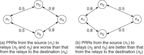
Table 5.3 Channel assignment, routing, and scheduling of opportunistic forwarding strategies for Figure 5.7(a) and Figure 5.7(b)

5.5.2 Simulation of Random Networks
In this subsection, we investigate the throughput bound of OR and TR in multiradio, multichannel systems and compare the results with that in single-radio, single-channel systems. We examine both linear topology and rectangle topology. For the linear topology, we uniformly deploy 12 nodes in a line with 300 units of length. For the rectangle topology, we randomly deploy 12 nodes in a rectangle area of 200 units × 300 units. We select node n1 at the left end (for the linear topology) and left corner (for the rectangle topology) of the networks as the destination, then calculate the throughput bound from other nodes to the destination using the LP formulations in Figure 5.2. There are therefore 11 different source–destination pairs considered in the evaluation for each topology. In all the simulations, we assume the packet reception ratio is inversely proportional to the distance with Gaussian random variation, which simulates the log-normal fading and two-ray path loss model. The transmission range is set as 100 units, and the interference range is set as twice of the transmission range. The performance metric is the normalized end-to-end throughput bound (by assuming the transmission rate is unit one). Note that although the network size is limited at 12 nodes in our simulation due to the exponential complexity of finding all the CTS's, this small network size is sufficient to allow us to gain insight of the opportunistic routing in multi-radio multi-channel networks. According to the simulation settings, the longest path between node 12 and 1 can be six hops and 11 hops in the rectangle and linear topologies, respectively. The shortest path between the node 12 and 1 can be 4 hops and 3 hops in the two topologies, respectively. So reasonable multihop network scenarios are simulated.
Figures 5.8 and 5.9 show the simulation result under linear topology and rectangle topology, respectively. In the legend, “TR” represents traditional routing, “OR” represents opportunistic routing, “xRyC − z” represents x radios and y channels, with z maximal number of forwarding candidates. That is, in the CTS enumeration, we only consider the opportunistic module that contains at most z number of forwarding candidates. We can see that performance shows similar trends under both topologies. With the number of radios and channels increasing, the throughput of TR and OR are both increased. Generally OR achieves higher throughput than TR, and the multiradio/channel capability has greater impact on the throughput of TR than OR. When the source is farther away from the destination, the OR presents more advantages than TR. Opportunistic forwarding using multiple forwarding candidates does help increase the throughput. An interesting result is that, for nodes 7 to 12, the throughput of 1R2C case for OR is comparable with or even greater than that of 2R2C case for TR. This result indicates that OR can achieve comparable or even better performance as TR by using less radio resource.
Figure 5.8 Normalized end-to-end throughput bound under different number of radios, channels and potential forwarding candidates in linear topology. Reproduced by permission of © 2010 IEEE.

Figure 5.9 Normalized end-to-end throughput bound with different numbers of radios, channels and potential forwarding candidates in rectangle topology. Reproduced by permission of © 2010 IEEE.
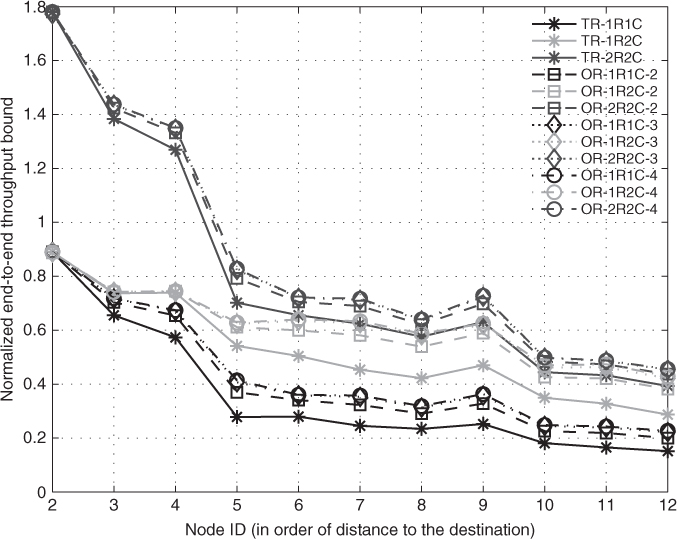
Another interesting observation is that the throughput gained decreases as the number of forwarding candidates increases. This result is consistent with that found in Zeng et al. (2007b,c). So it is not necessary to involve all the usable receivers of the transmitter into the opportunistic forwarding and selecting a few “good” forwarding candidates is enough to approach the optimal throughput. This theoretical observation may help us design practical protocols.