
7.6 CodePlay: a Live Multimedia Streaming Scheme for VANETs Based on SLNC
In this section, we study the cooperative broadcast of live multimedia streams (LMS) in VANETs. We present CodePlay, a distributed live multimedia streaming scheme in VANETs based on SLNC. We should note that, unlike general popular content distribution services in VANETs in the last section where the main goal is high average downloading rate, LMS services require not only a high average streaming rate but also demand that the streaming rate keep stable for the purpose of smooth playback. LMS services are also different from nonlive streaming services such as video-on-demand, where various vehicles may be interested in different contents and those contents are not closely related to the real world's time. For LMS services, the streaming contents are usually generated as time progresses and are only useful to vehicles within a short period of time, for example several seconds to tens of seconds. However, these time constraints are usually not as tight as those of real-time services, like intelligent collision avoidance, which usually require a delay smaller than hundreds of milliseconds.
In addition to a stable and high streaming rate for smooth playback and short service delivery delay, LMS also needs high bandwidth efficiency for better coexistence with other competing services. In a dynamic and lossy VANET, the biggest challenge to providing satisfiable LMS services is how to achieve the above multiple objectives simultaneously.
As we already mentioned in Section 7.2, in this section we approach the LMS problem in VANETs using SLNC again, due to its potential to alleviate packet losses and enhance space reusability. However, providing satisfiable LMS services with minimal bandwidth is not a trivial problem even with the help of SLNC. Essentially, this corresponds to the following core design issue: which vehicles should transmit what content to whom at which service time slots? In particular, as broadcast is adopted as the basic transmission paradigm and multiple receivers may have different stream reception and playback status, how do we select proper relay nodes to ensure smooth playback of multiple vehicles? How to coordinate the transmission of multiple relays so that spacial reusability is maximized? How can the above be achieved efficiently with low overheads? All these key issues imply that new design considerations are needed.
To this end, the main contribution of CodePlay is to introduce a coordinated local push (CLP) mechanism based on SLNC, which features a mixed lightweight transmission coordination strategy. From the global level, the whole AoI is divided into segments of fixed length and within each segment a relay node will be selected. The transmission schedule among the adjacent segments follows a deterministic scheduling method in order to disseminate the streaming content from sources to all the segments smoothly and in a timely manner. From the local level, within each segment a lightweight coordination mechanism is used to ensure the (dynamic) selection of one relay node whose transmissions can bring the most amount of useful information to all the vehicles in its neighborhood and will ensure the LMS delivery before the desired deadline to each neighboring vehicle as much as possible. Again, the CLP mechanism benefits from the use of network coding in simplifying the transmission coordination and scheduling.
Furthermore, to enhance the LMS performance for sparse VANETs, an opportunistic transmission scheduling algorithm is proposed, where the wasted transmission opportunities in the network can be adaptively utilized by the relays, merely based on carrier sensing. The organization of rest of this section is similar to the previous section.
7.6.1 Design Objectives
Live multimedia streaming is one typical delay-bounded application with QoS requirements. Thus, the design of CodePlay pursues the following primary objectives.
- Smooth playback at all the interested vehicles, which refers to all vehicles inside AoI. This requirement can be translated into providing a stable and high streaming rate.
- Prompt service delivery, which can be translated into short end-to-end delay for all the receivers. For a receiver, this delay is defined as the elapsed time from the generation of specific LMS content at the source to the start of playback of this content at the receiver. Meanwhile, it is desirable to achieve a high degree of fairness, i.e., the service delays among neighboring receivers should be similar.
- Minimized bandwidth cost, which can be translated into incurring small protocol overhead and data traffic. This is for better coexistence with other possible services.
7.6.2 Overview of Codeplay
We will first give an overview of CLP from the macroscopic level and then show a simple example of CodePlay's protocol run.
7.6.2.1 Global View
A random access control protocol such as CSMA/CA is widely used to coordinate local transmissions within a neighborhood. However, from a global point of view, such a protocol cannot ensure the fast and smooth propagation of information flow across the multihop VANET within the AoI. For applications such as live multimedia streaming, where each packet has a playback deadline, such a protocol is inadequate. CodePlay divides the whole AoI into segments of fixed length, which can be referred to as the logical segmentation of communication path approach. This is possible because such configuration can be broadcast to vehicles by APs and it is also not difficult for a vehicle to determine which segment it is in with GPS. Within each segment, a relay node will be selected based on the ideas presented in the previous section. The transmission schedule among the adjacent segments must follow some deterministic scheduling method. Figure 7.22 shows the effect of such segmented prorogation idea, where the scheduling is simply round robin. In time slot 1, the AP, selected relay nodes in segment 3 and segment 6 are transmitting. In time slot 2, relay nodes in segments 1, 4, 7 are transmitting. In time slot 3, relay nodes in segments 2, 5, 8 are transmitting. This will ensure the smooth prorogation of the contents along the AoI, with roughly one segment length per time slot.
Figure 7.22 Coordination for LMS in VANET: segmentation of communication path. © 2011 IEEE. Reprinted, with permission, from Z. Yang, M. Li and W. Lou, “CodePlay: Live Multimedia Streaming in VANETs using Symbol-Level Network Coding”, IEEE Transactions on Mobile Computing (TMC), 2011.

7.6.2.2 Example of Codeplay's Protocol Run
In the following, we illustrate the workflow of CodePlay using a simple example. For proof-of-concept, we describe CodePlay under a one-dimensional highway scenario (Figure 7.23). However, CodePlay can be easily extended to the urban scenario, i.e., a two-dimensional case.
1. System initialization. To ensure smooth playback in LMS, node coordination shall be facilitated in an efficient way, yet, in a dynamic VANET. The idea of CLP is that, we introduce road segmentation during initialization so that coordination decisions can be made locally9. Each road is divided into fixed segments of equal length (SL) and is uniquely numbered. The road segmentation can be preconfigured and provided by the access points with the help of GPS. Every vehicle is assumed to possess this information before entering the AoI.
2. Local coordinator selection. In order to make the relay selection process reliable and efficient, the key method is to let vehicles agree on a local coordinator, which selects the relay on behalf of other nodes (Figure 7.23(a)). This is achieved by taking advantage of the obligated safety message service in the control channel required by the IEEE 802.11p standard, where every vehicle has to broadcast a safety message to inform its current location in each control time slot. CodePlay lets each vehicle piggyback a short piece of additional information on the safety message. This information contains the minimum Euclidean distance to the geographical center of the road segment that this vehicle knows (either its own distance to the center or the broadcasted distance overheard from other vehicles in the same segment) and also the vehicle's current LMS content reception and playback statuses. We will introduce an efficient representation of this information later. The vehicle closest to the center of the segment is selected as local coordinator, like vehicle B in Figure 7.23(a).
3. Distributed relay selection. The coordinator selects real relay based on the reception and playback status of all nearby vehicles, i.e., what LMS contents each of them have received or are needed for playback in the immediate future. In particular, the coordinator computes the utility of each node in its segment as how much useful information can that node provide to its neighbors, and designates that node as relay via unicast. This is shown in Figure 7.23(b), where coordinator B designates vehicle C as relay and the generation G2 as the broadcasted content. One generation represents a short period of LMS content and the precise definition will be given in the following section.
4. Local push and transmission coordination of relays. In order to create a stable and continuous LMS flow, only relays in certain segments are allowed to transmit concurrently in each service time slot. Those relays actively “push” coded LMS blocks to their vicinity, which will be received by neighboring vehicles. To maximize spacial reusability, we exploit SLNC's symbol-level diversity by purposely reducing the distance between two concurrent transmitting relays (thus introducing a proper amount of signal interference). In the snapshot given in Figure 7.23(c), the two relays are separated by two road segments, which maybe too close to be allowed if packet level collision avoidance mechanism is adopted. Specifically, we address the following issues: 1. what is the optimal number of segments between two adjacent transmitting relays? 2. how can we opportunistically schedule the relays' transmission if the density of the VANET is so sparse that some road segments are empty and no relay could be selected for them?
7.6.3 LMS Using Symbol-Level Network Coding
The integration of SLNC is similar to that of CodeOn in Section 7.5. The definition of generations and pieces, the piece-division, run-length coding algorithm are the same.
The main difference is that, each receiver v maintains a playback buffer for generations to be played in the immediate future, which buffers all the received useful coded symbols. Note that v also maintains a decoding matrix for each symbol position j of each generation, which consists of the coding vectors of all the jth symbols. Again, the rank of each matrix is called symbol rank. A coded symbol is called useful in CodePlay if: 1. it is received correctly (Katti et al. 2008); 2. it can increase the corresponding symbol rank (innovative); 3. it belongs to a generation that is after v's current playing point. When receiving enough useful symbols for a position, the receiver can decode the original symbols by performing Gaussian elimination on the corresponding matrix.
Like CodeOn, CodePlay also uses the average symbol rank reception status representation method. It exploits multichannel capability by piggybacking the node's average symbol rank information of each generation in safety messages in the control channel. Here is a back-of-the-envelope calculation: for ten generations with packet length of 30 symbols and K = 32, the piggybacked information is only about ten bytes, which can be easily embedded in a safety message without affecting its reliability (Xu et al. 2004).
Each node plays the buffered generations sequentially and keeps eliminating older generations to make room for newer content. Those generations within α seconds after the current playback time are called priority generations. The piggybacked reception status, which contains a priority generation with average rank less than K is considered as an implicit urgent request. The above definitions are depicted in Figure 7.24. Note that vehicles on the opposite road of the AoI behave exactly the same as described above except that they do not need to playback the received LMS contents.
Figure 7.23 The concept of coordinated local push. Reproduced by permission of © 2011 IEEE.

Figure 7.24 Playback buffer and priority generations. Reproduced by permission of © 2011 IEEE.

7.6.4 Coordinated and Distributed Relay Selection
The main purpose of the relay selection is to maximize the utility of each transmission to save the precious bandwidth resource in the VANET. The selected relays should best satisfy all neighbors' smooth playback needs, which can be inferred through vehicles' reception statuses. Here three components are needed: 1. a local coordinator that serves as an arbitrator, with which a consensus on relay selection can be reliably and efficiently achieved; 2. the computation of nodes' “utilities” that represent their capability to satisfy others; 3. The selection of appropriate parameters (such as segment length) for fast LMS propagation and continuous coverage.
7.6.4.1 Distributed Coordinator Selection
All vehicles in the same road segment agree on an unique local coordinator at the end of each control time slot, based on geographic information. For both reliability and efficiency considerations, we propose an accumulated consensus mechanism based on information piggybacked in the safety messages. We firstly define a temporary coordinator as the vehicle closest to the segment center that a vehicle currently knows. Each vehicle considers itself as the default temporary coordinator at the beginning of each control time slot. For each overheard safety message originated from a vehicle in the same segment, the receiver checks if the temporary coordinator piggybacked (Figure 7.25) is closer to the segment center than the one known to itself presently. If yes, the receiver replaces its temporary coordinator with the overheard one. Since the vehicle closest to the segment center will be repeatedly claimed as temporary coordinator by multiple safety messages (like vehicle B in Figure 7.23(a)), this accumulated consensus mechanism makes the probability of selecting multiple coordinators within one segment negligible, no matter there are lossy wireless links or sparse connections.
Figure 7.25 The format of piggybacked information (in bytes), where N is the size of the playback buffer (in generation). Reproduced by permission of © 2011 IEEE.

7.6.4.2 Relay Selection
At the beginning of the following service time slot, each coordinator C firstly checks if its segment is scheduled to transmit in this slot or not, where the scheduling algorithm will be introduced in the next section. If yes, C will then calculate the node utility for each vehicle in ![]() , the set of all the vehicles in the same segment as C, and designate the one with the highest utility as relay. If a tie appears, the vehicle located in the LMS propagation direction wins. The calculation of node utility consists of two steps:
, the set of all the vehicles in the same segment as C, and designate the one with the highest utility as relay. If a tie appears, the vehicle located in the LMS propagation direction wins. The calculation of node utility consists of two steps:
1. Find the range of interested generations for all vehicles in ![]() , which is the neighbor set of C and we require
, which is the neighbor set of C and we require ![]() . Only the generations representing streaming contents after the earliest playback time among vehicles in
. Only the generations representing streaming contents after the earliest playback time among vehicles in ![]() are regarded as interested ones. If there exists some urgent generations UrgentGen, C will give strict priority to the transmission of UrgentGen during this time slot to ensure smooth playback at those vehicles. Otherwise, all the interested generations will be considered by C.
are regarded as interested ones. If there exists some urgent generations UrgentGen, C will give strict priority to the transmission of UrgentGen during this time slot to ensure smooth playback at those vehicles. Otherwise, all the interested generations will be considered by C.
2. Calculate node utility for each vehicle in ![]() . If UrgentGen ≠ Ø, only the generations in it will be considered in this calculation. With SLNC, the usefulness of a potential relay v's generation Gi is determined by the difference in the symbols' ranks of Gi between v and its neighbors. Due to wireless medium's broadcast nature, Gi's utility to others increases with both the average usefulness of Gi and the number of vehicles it can benefit. Thus, for
. If UrgentGen ≠ Ø, only the generations in it will be considered in this calculation. With SLNC, the usefulness of a potential relay v's generation Gi is determined by the difference in the symbols' ranks of Gi between v and its neighbors. Due to wireless medium's broadcast nature, Gi's utility to others increases with both the average usefulness of Gi and the number of vehicles it can benefit. Thus, for ![]() , the generation utility of Gi is defined as:
, the generation utility of Gi is defined as:
7.14 ![]()
where ![]() is the fussy average rank of node v's generation i. Step(x) = x, if x > 0; otherwise, Step(x) = 0. And Urgent(Gi, v′) = priValue, if Gi is urgently requested by vehicle v′, otherwise,
is the fussy average rank of node v's generation i. Step(x) = x, if x > 0; otherwise, Step(x) = 0. And Urgent(Gi, v′) = priValue, if Gi is urgently requested by vehicle v′, otherwise, ![]() , where i0 is the index of the urgent generation closest to the physical world's time. The priValue is an adjustable system parameter that controls the relative importance of priority generations. Note that, as the coordinator does not know
, where i0 is the index of the urgent generation closest to the physical world's time. The priValue is an adjustable system parameter that controls the relative importance of priority generations. Note that, as the coordinator does not know ![]() under the single-hop piggyback mechanism, we substitute
under the single-hop piggyback mechanism, we substitute ![]() by
by ![]() . In fact, if we assume the safety messages are sent at the basic rate that can reach a larger range (e.g. 2 × ) than normal data packets, then
. In fact, if we assume the safety messages are sent at the basic rate that can reach a larger range (e.g. 2 × ) than normal data packets, then ![]() can be further reduced to nodes within v's data communication range (
can be further reduced to nodes within v's data communication range (![]() ) (which will be explained later), which can be estimated by C.
) (which will be explained later), which can be estimated by C.
This utility measures how much innovative information node v can give to other vehicles in ![]() in total if it broadcasts coded packets generated from Gi. Currently we do not consider the link qualities between v and the receivers. The node utility U(v) of vehicular node v is defined as
in total if it broadcasts coded packets generated from Gi. Currently we do not consider the link qualities between v and the receivers. The node utility U(v) of vehicular node v is defined as ![]() , which estimates the maximum amount of innovative information v can provide to other vehicles in
, which estimates the maximum amount of innovative information v can provide to other vehicles in ![]() for one generation. We do not look at the aggregate utility of multiple generations, because transmitting many generations takes a long time, which may cross multiple time slots and the VANET topology will have already changed.
for one generation. We do not look at the aggregate utility of multiple generations, because transmitting many generations takes a long time, which may cross multiple time slots and the VANET topology will have already changed.
The coordinator C designates R, the vehicle having the maximum U(R), as the relay using a unicast message, which enables R to use the current service time slot. R then actively pushes coded packets generated from GR with the maximum U(GR, R). Note that the required number of coded pieces to send during one service time slot can be estimated based on ![]() , which will not be elaborated here.
, which will not be elaborated here.
7.6.4.3 Determining the Segment Length
The length of the segment, SL, is an important parameter that affects the utility of relay selection and propagation speed of the LMS flow. On the one hand, if SL is too large, a relay at one end of a segment may not convey enough information to the neighboring segment in its scheduled time slot and in the next slot the relay in the neighboring segment would have little innovative information to transmit, which affects smooth playback of LMS. On the other hand, if SL is too small, vehicles in adjacent segments tend to have similar reception statuses and their relays probably will transmit duplicate information. Both extremes could lead to low bandwidth efficiency and large service delivery delay.
In general, we should ensure that for a sender and receiver pair of distance SL, the symbol reception probability is sufficiently high. However, with a realistic fading channel, it is hard to define such a range because symbol reception is probabilistic. For a simpler alternative approach, we define an equivalent data communication range CR under free space propagation model(Friis) as before: ![]() , where Tp is the transmission power, G is the antenna gain and ThCR is the data reception threshold. Thus we set SL ≈ CR in this chapter.
, where Tp is the transmission power, G is the antenna gain and ThCR is the data reception threshold. Thus we set SL ≈ CR in this chapter.
7.6.5 Transmission Coordination of Relays
We have determined which vehicles should transmit what content to whom. In this section, we answer the last question: in which time slots should each relay actively push the coded LMS? This is addressed from both spacial and temporal aspects.
7.6.5.1 Spacial Coordination
Due to the use of SLNC, concurrent transmissions of more relays are encouraged to take advantage of spacial reusability (Katti et al. 2008). But two transmitting relays that are too close will cause heavy collisions, which in turn degrades the bandwidth efficiency. There exists an optimal average distance between two concurrent transmitting relays, dopt, under which the relays can convey the highest amount of useful information to their neighbors within unit time. In other words, the bandwidth can be used most efficiently.
Next we discuss how to determine the dopt. Consider a straight highway of length L, where vehicles are uniformly distributed. n relays, v1, v2, ……, vn, lie on the highway with equal inter distance. From the same analysis in Section 7.4, the “optimal inter relay distance” is derived as the inter relay distance that maximizes the average symbol reception probability for all the vehicles in the VANET. The results are referred to in Figures 7.8(a) and 7.8(b).
In CodePlay, the channel access decisions are made largely based on carrier sense. We also exploit this characteristic in the opportunistic scheduling algorithm in the next section.
7.6.5.2 Temporal Coordination
To provide continuous streaming coverage and to satisfy the strict time constraint of LMS service, the traditional random medium access mechanisms are not appropriate since their channel access delays are not bounded. We propose to use local round-robin (LRR) scheduling to coordinate the transmissions of neighboring relays. At first, we define the number of separating segments between two adjacent transmitting relays as Wopt, which can be calculated as ![]() . The round length R in LRR is exactly Wopt + 1. For a relay in segment i, its scheduled slots Ti are determined as: Ti ≡ i mod (Wopt + 1). For example, assume Wopt = 2, then segment 1 is scheduled to use time slots 1, 4, 7, 10, etc. Using this local round-robin schedule, LMS can flow from the source to receivers within the AoI smoothly. From a receiver's point of view, if the VANET is well connected, it is always able to obtain new LMS content for playback within determined waiting time.
. The round length R in LRR is exactly Wopt + 1. For a relay in segment i, its scheduled slots Ti are determined as: Ti ≡ i mod (Wopt + 1). For example, assume Wopt = 2, then segment 1 is scheduled to use time slots 1, 4, 7, 10, etc. Using this local round-robin schedule, LMS can flow from the source to receivers within the AoI smoothly. From a receiver's point of view, if the VANET is well connected, it is always able to obtain new LMS content for playback within determined waiting time.
7.6.6 OLRR: Opportunistic LRR Scheduling for Sparse VANETs
Due to the highly dynamic nature of VANET, it tends to experience partitions frequently (Park et al. 2010), especially when the traffic density is low. In sparse VANET, some road segments will be devoid of relays and the scheduled transmission opportunities would be wasted, which results in low bandwidth efficiency. This is illustrated in Figure 7.26(a), where the segments 4, 7, 10 contain no vehicles, and their scheduled time slots are wasted. To solve this problem, we propose an opportunistic LRR (OLRR) scheduling algorithm by taking advantage of those available slots.
Figure 7.26 Sparse VANETs (T = 1, R = 3). (a): LRR wastes transmission opportunities. (b)-(c): Using OLRR, secondary segments can take the unused transmission opportunities of primary segments (4,7,10). Reproduced by permission of © 2011 IEEE.

The OLRR operates in a way resembling cognitive radio, which leverages nodes' carrier sensing capability. Essentially, during each service time slot, the coordinators in each segment will detect if there are relays in the nearby primary segments, which are scheduled segments by LRR in that time slot. If not, certain secondary segments will gain channel access according to some priority assignment. In order to sense the channel, a few additional rounds (3 × (Wopt + 1) subslots) are allocated before data transmission. Thanks to SLNC, each coordinator/relay does not need to consider the transmitters out of its energy detection capability, which greatly simplifies protocol design.
The algorithm is described in Algorithm 7.1 In line 3, there are two cases where a relay cannot be selected: Ci is the only node in i, or no node can provide innovative information to others. ConflictSet(i) is the set of coordinators (also segments) that has higher transmission priority than i. The nearer a segment is to a primary segment (with lower ID), the higher its priority. If two secondary segments happen to have the same distance to their primary segments, they will both access the channel as is the case in LRR.
We use the examples in Figure 7.26 to illustrate the basic idea of OLRR. Suppose Wopt = 2 and C1, C4, C7, C10 are scheduled to use the channel simultaneously in the current service-time slot. In Figure 7.26(a), C5 will decide to take this time slot since it senses that C4 and C7 do not exist. The same for C8 and C11. For Figure 7.26(b), C8 will give up this opportunity since otherwise it will incur unnecessary interference to the transmission of C10. The situation in Figure 7.26(c)
Algorithm 7.1 Opportunistic LRR scheduling at each coordinator
              (at the beginning of a service channel slot)
1: Input: Coordinator Ci, segment ID i, round length R = Wopt + 1 2: Output: Whether to allow the relay access channel 3: If Ci is able to select a relay from i 4: Broadcast a short signal in the subslot i′ ← i mod 3R ConflictSet(i) ← ∅ 5: For subslot j′ from 0 to 3R − 1//determine which segments have relays 6: If sensed signal during j′ 7: ConflictSet(i) ← ConflictSet(i)∪Segmentj,
             where Segmentj is the nearest one to i between the two:
            j′ + i − i′ and j′ + i − i′ ± 3R //the most probable segment
8:  Prune from ConflictSet(i) the segments that are more than R
     segments away from i             //regarded as not conflicting
9:  Prune from ConflictSet(i) segments j with j mod R > i mod R
     //the one nearer to a primary segment has higher priority
10: If ConflictSet(i) ≠ ∅
11:      Ci tells relay in i to abort transmission
12: Else, Ci tells relay in i to access the channel in current service
    time slot
is a little different. Now C6 and C8 will try to take extra transmission opportunities left by empty segments 4 and 7 respectively. To avoid heavy collision between them, OLRR assigns each secondary segment a priority based on its distance to the primary segment with lower ID. In this case, C8 has higher priority and will take this transmitting opportunity.
Finally, the reason we have 3 × (Wopt + 1) subslots is to ensure that each coordinator will be able to determine a unique segment (w.h.p) that is transmitting in each subslot. Since the sensing process is purely based on detecting the energy, the time overhead can be negligible. In CodePlay, we set the sensing signal length to be 50 bytes and the length of each sub slot to be 100 μs, which takes preamble, SIFS, etc. into consideration. For Wopt = 2, the total extra time is 3 × (2 + 1) × 100 = 900 μs, which is less than 2% of a service time slot with length of 50 ms.
7.6.7 Performance Evaluation
We implemented and evaluated CodePlay by simulations using NS-2.34. The SLNC is implemented based on Katti et al. (2008), with an enhanced run-length coding technique, which is more suitable for consecutively broadcasting a generation of coded pieces in CodePlay. To ensure unique coordinator selection within the same segment, at the beginning of service time slots use an additional broadcast round (shorter than 1 ms) to resolve collisions between potential coordinators. The simulation scenario consists of a straight four-lane highway and one or two LMS source(s) (e.g., access points) can be located at one or both ends of the highway. The upper part of the highway (west bound) is regarded as the AoI. We simulate both dense and sparse VANETs by using two traffic densities: 66.7 cars/km and 35.5 cars/km. The vehicular speeds are randomly selected from 20–30 m/s. The simulation parameters are shown in Table 7.5.
Table 7.5 Parameter settings
| Data rates for LMS and safety msg. | 12 mbps, 3 mbps |
| Data communication range | CR = 250 m |
| Time per generation, piece size | 2 s, 1 KB |
| Safety message length (with piggyback) | 130B |
| Buffer capacity | 15 generations |
| PriValue | 32 |
| No. of generations in priority region | α = 1 |
Reproduced by permission of © 2011 IEEE.
The protocol for comparison is the PLNC version of CodePlay (CodePlay+PLNC) and the Wopt for PLNC is used. The closest state-of-the-art LMS scheme to ours is emergency video dissemination in VANETs using PLNC (NCDD), Park et al. 2010). However NCDD was not designed to meet the practical application layer requirements defined in this chapter, and it is hard to evaluate those metrics based on NCDD protocol. Thus we chose to not implement NCDD, but we have compared our results with the reported ones in Park et al. (2010).
The performance of CodePlay is evaluated by multiple metrics. 1. Initial buffering delay, which is the user experienced service delay. In the simulation, we impose the same initial buffering delay for all receiving vehicles. 2. Source rate, which reflects the supported LMS generation rate from the application layer. 3. Skip ratio, the fraction of generations skipped due to incomplete reception before playback time over all the generations that are played. Buffering level, the percentage of the buffered LMS contents between current playback time and physical world time. They both reflect the playback quality, i.e., smoothness (Wang and Li 2007).
7.6.7.1 Effect of Number of LMS Sources
We first consider how the LMS performance is affected by the number of sources (AP), i.e., only one AP, which is placed on one end of the highway, or two at both ends of it. Our main finding is that, the two-source case significantly outperforms the single-source case. Figure 7.27 shows the difference between using one and two APs under the dense highway with length L = 2250 m. Both protocols, CodePlay+SLNC and CodePlay+PLNC perform much better under the two-AP case than the single-AP case. Another observation is that CodePlay+PLNC cannot work well even in the two-AP case, the skip ratio of which is as high as 24%. However, the adoption of SLNC can reduce the skip ratio to less than 8%, which enables a much better playback experience.
Figure 7.27 Comparison between using one and two APs, dense highway, source rate = 12 KB/s, initial buffering delay = 16 s. Reproduced by permission of © 2011 IEEE.

This can be explained as follows. Because of lossy wireless links, a single flow is not able to sustain smooth playback of the LMS content after traversing a large number of hops in the VANET, which is also in line with the conclusions of routing throughput in multihop wireless networks. For two crossing flows with the same content, the packet losses are compensated by innovative symbols/packets from both directions. This can also be proved by the higher buffering levels in the two-AP case shown in Figure 7.27(b). Therefore, in the following we evaluate CodePlay based on the two-AP case.
7.6.7.2 Initial Buffering Delay and Smooth Playback
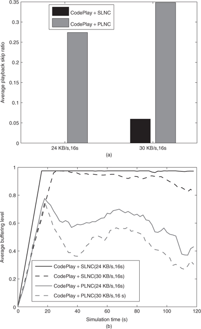
To further illustrate the advantage of CodePlay in providing better LMS services in VANET, we investigate the relationship between initial buffering delay, source rate and the metrics for smooth playback under a relatively sparse highway scenario. In the first simulation set, we fix initial the buffering delay as 16 s and increase the source rate from 24 KB/s to 30 KB/s. The results are presented in Figure 7.28. We can see that the skip ratio for CodePlay+SLNC is much lower that its PLNC-based component, where the former's skip ratio is 0 under 24 KB/s and 6% under 30 KB/s. This suggest that rates up to 30 KB/s could be supported without affecting smooth playback. Also, for each rate CodePlay+PLNC's buffering level decreases faster over time and is less stable compared with that of CodePlay+SLNC. This reflects that CodePlay+SLNC achieves a more stable flow of multimedia streaming, which shows the effectiveness of the integration of SLNC with the coordinated local push mechanism. We note that, the NCDD protocol only provided 10 KB/s source rate for video dissemination (Park et al. 2010).
Figure 7.28 Fixed initial buffering delay, varying source rates. Sparse highway. Reproduced by permission of © 2011 IEEE.
In the second simulation set, we fix the source rate as 30 KB/s and increase the initial buffering delay from 16 to 24 s. From Figure 7.29, we can see an obvious reduction in the skip ratio for the CodePlay+SLNC, from 6% to 0.8%, and an increase in the buffering level for both protocols. This result is consistent with intuitions and implies that initial buffering delay plays an important role in VANET LMS services.
Figure 7.29 Fixed rate, varying initial buffering delay. Sparse highway. Reproduced by permission of © 2011 IEEE.

The CodePlay+SLNC works well through all source rates no greater than 30 KB/s, and for buffering delays of 16 s and 24 s. We argue that those delays are acceptable in VANETs. For example, for a delay equal to 16 s and vehicular velocity of 30 m/s, a car will travel about 500 m after it enters the AoI to begin playing an emergency multimedia content. For L = 2250 m, the car will be at 1750 m from the accident spot and may still have enough time to take actions.
7.6.7.3 Effect of Traffic Density
Next we study the performance of CodePlay under the dense traffic condition. Figure 7.30 shows the whole set of simulation results with various source rates and buffering delays. Though CodePlay+SLNC still outperforms CodePlay+PLNC, compared with the sparse case, the skip ratios of both protocols are higher and buffering levels lower. Especially, the skip ratio reaches up to more than 10%, which could be unacceptable from application layer. We have observed (not shown) that the relay selection is almost always unique and is highly reliable, therefore the worse performance can be mainly ascribed to limitations in the node utility functions, which are directly associated with how much innovative information a relay can deliver to all neighboring nodes. For broadcasting in a dense VANET, since there could be too many vehicles urgently demanding different portions of the LMS content, it is intrinsically hard to satisfy all their needs in a short time. Due to the time constraints of LMS applications this leads to more frequent playback skips than in the sparse VANETs.
Figure 7.30 Impact of traffic density. Dense highway. Reproduced by permission of © 2011 IEEE.

7.6.7.4 Effect of Opportunistic Scheduling
In the previous simulations for sparse scenario, we have the OLRR scheduling enabled by default. Yet it is interesting to see how the opportunistic scheduling affects the protocol performance. Thus, we presented in Figure 7.31 the results of enabling and disabling the OLRR algorithm (using LRR instead). All the protocols run with source rate of 30 KB/s and initial buffering delay of 16 s. We can see that the OLRR much improves the performance over the basic LRR algorithm, which reduces the skip ratio from 20% to 6%. By opportunistically utilizing the idle scheduled transmission slots left by primary segments, the OLRR can adaptively “fill” the unnecessary gaps created during the propagation of the LMS flow. And this mechanism works especially well for SLNC, because the transmission tends to be more reliable over larger distances.
Figure 7.31 Effect of opportunistic transmission scheduling. Reproduced by permission of © 2011 IEEE.

Remark. To summarize, from the above results of CodePlay, we can obtain the following main implications: 1. LMS services in VANET with high source rates are hard, yet feasible to provide with satisfiable user experience. Even using SLNC, we may need the help of few additional infrastructure (APs) along the road to facilitate the dissemination of LMS. 2. Using CodePlay with SLNC, the playback smoothness can be greatly enhanced over traditional protocols for source rates up to 30 KB/s, and with acceptable buffering delay, especially in sparse VANETs.