Chapter 12
Conclusions and Future Research
12.1 Chapter 1: Introduction
This chapter constituted the general background of our studies throughout the book. More specifically, a brief overview of the literature of source encoding and soft source decoding was presented in Section 1.1.1. Then the development of iterative decoding techniques and their convergence analysis was described in Section 1.1.3. Furthermore, as a special case of iterative decoding, joint source–channel decoding was introduced and the main contributions to the open literature were summarized in Section 1.1.2. Finally, the organization of the book was described in Section 1.4, while our novel contributions were highlighted in Section 1.5.
12.2 Chapter2:Information Theory Basics
In this chapter we focussed our attention on the basic Shannonian information transmission scheme and highlighted the differences between Shannon’s theory, valid for ideal source and channel codecs as well as for Gaussian channels, and its ramifications for Rayleigh channels. We also argued that practical finite-delay source codecs cannot operate at transmission rates as low as the entropy of the source. However, these codecs do not have to operate losslessly, since perceptually unobjectionable distortions can be tolerated. This allows us to reduce the associated bit rate.
Since wireless channels exhibit bursty error statistics, the error bursts can only be randomized with the aid of infinite-length channel interleavers, which are not appropriate for real-time interactive multimedia communications. Although with the advent of high-delay turbo channel codecs it is possible to operate near the Shannonian performance limits over Gaussian channels, over bursty and dispersive channels different information-theoretical channel capacity limits apply.
We considered the entropy of information sources both with and without memory and highlighted a number of algorithms, such as the Shannon–Fano, the Huffman and run-length coding algorithms, designed for the efficient encoding of sources exhibiting memory. This was followed by considering the transmission of information over noise-contaminated channels, leading to Shannon’s channel coding theorem. Our discussions continued by considering the capacity of communications channels in the context of the Shannon–Hartley law. The chapter was concluded by considering the ramifications of Shannon’s messages for wireless channels.
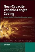
Figure 12.1: Evolution of the RVLC codeword length histograms. The RVLC is designed for the English alphabet, and its detailed construction process is described in Section 3.3.4.2. The codeword length distribution is optimized via a number of iterations for the sake of reducing the average codeword length.
12.3 Chapter3: Sources and Source Codes
Chapter 3 commenced with the description of general source models, among which a memoryless source model having a known finite alphabet, such as that described in Section 3.2, was used throughout the monograph. Then various source codes such as Huffman codes, RVLCs and VLEC codes were introduced in Section 3.3, along with their construction methods. An important contribution of this chapter is that a generic algorithm was presented for the construction of efficient RVLCs and VLEC codes. The philosophy of our proposed algorithm is that we first construct an initial RVLC or VLEC code using existing methods such as those described in [21, 23, 30], and then we optimize the codeword length distribution of the resultant code length by length. For example, Figure 12.1 shows the evolution of the codeword length histograms of the RVLC designed for the English alphabet in Section 3.3.4.2. After 12 iterations of optimization, the best codeword length distribution is found, resulting in a RVLC having the lowest average codeword length of AL = 4.18732.
Consequently, as shown in Tables 3.3, 3.4 and 3.5, for a variety of memoryless sources the proposed algorithm was capable of generating RVLCs of higher code efficiency and/or shorter maximum codeword length than the algorithms previously disseminated in the literature. Furthermore, as seen from Tables 3.9 and 3.10, the proposed algorithm was also capable of constructing VLEC codes having similar code efficiency to those generated by the existing algorithm [29], but incurring a significantly lower complexity.
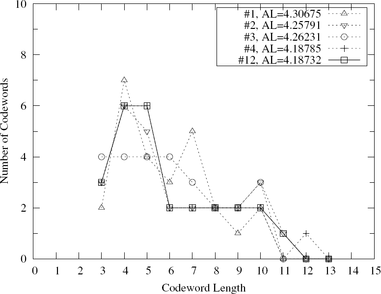
In Section 3.4 various VLC decoding methods were presented. First, the source information, such as the number of bits or symbols in the transmitted frames, and the constraints imposed by a source code and formulated in terms of the corresponding codebook, were translated into a trellis representation, such as the symbol-based trellis described in Section 3.4.1.1 or the bit-based trellis described in Section 3.4.1.1. Then MAP/ML sequence estimation or MAP decoding could be performed, as introduced in Sections 3.4.2.1 and 3.4.2.2 respectively. It was shown in Section 3.4 that trellis-based soft decoding provides an effective way of capitalizing on the available information as much as possible. In general, the more information is utilized, the better the performance. This information can be explicit, such as the transmission frame length information, or implicit, such as the code constraint of a VLC. For example, soft decoding generally outperforms hard decoding, and the symbol-level trellis-based decoding outperforms the bit-level trellis-based decoding. Furthermore, as expected, VLCs having higher free distances outperform VLCs having lower free distances at the price of a reduced system throughput. Figure 12.2 provides some quantitative results, summarizing the conclusions of Section 3.4. It can be seen from Figure 12.2a that soft-decision decoding significantly outperforms hard-decision decoding and the attainable Eb/N0 gain improves upon increasing the VLC’s free distance. Moreover, as seen from Figure 12.2b, the performance of soft ML decoding improves upon increasing the free distance of the VLC used.
12.4 Chapter4: Iterative Source–Channel Decoding
Chapter 4 provided an investigation of iterative source–channel decoding techniques. In this chapter the source code, the channel code and the ISI channel were viewed as a serially concatenated system. Hence, iterative decoding could be performed, provided that the source decoder, the channel decoder and the channel equalizer designed for the ISI channel were all SISO modules.
This chapter commenced with an overview of various concatenated schemes, as described in Section 4.1. Then a SISO APP decoding algorithm was introduced in Section 4.2.1. This algorithm provides a general description of any trellis-based APP decoding/detection scheme, which can be applied to source decoding, channel decoding and channel equalization. Hence it constitutes the core module of iterative decoding schemes.
EXIT charts were introduced in Section 4.2.2. The mutual information between the data bits at the transmitter and the soft values at the receiver was used for characterizing the decoding behavior of a SISO APP module, resulting in the so-called EXIT functions. A histogram-based algorithm and its simplified version were introduced in Section 4.2.2.3 in order to evaluate the EXIT functions of a SISO APP module, followed by several examples of typical EXIT functions of SISO APP modules embedded in different positions of a concatenation scheme.
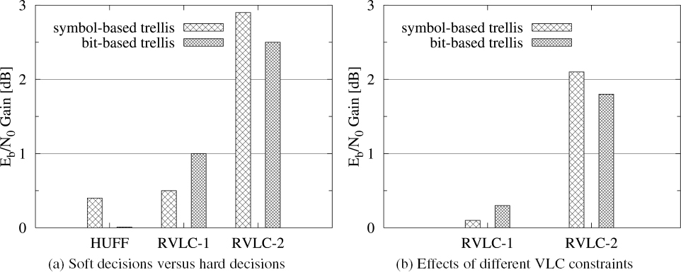
Given the EXIT characteristics of the constituent modules of a concatenated scheme, we may either predict or explain its convergence behavior. This was carried out for iterative source–channel decoding for transmission over non-dispersive AWGN channels in Section 4.3 and for transmission over dispersive AWGN channels in Section 4.4. In the scenario of non-dispersive AWGN channels, it was shown in Figure 4.15 that the free distance of the source code has to be larger than df = 2 in order that the iterative decoding scheme becomes capable of converging to the perfect mutual-information point of (1, 1), which implies attaining infinitesimally low SERs. Furthermore, it was shown in Figures 4.17–4.24 that given a specific channel code, the system’s convergence threshold decreases upon increasing the free distance of the source code, resulting in an improved SER performance. Figure 12.3 serves as a summary of our main results provided in Section 4.3. It is worth noting that when the free distance of the VLC code is increased from df = 1to df = 2, i.e. when using the code RVLC-2 instead of the code HUFF or RVLC-1, the system’s throughput is only slightly decreased, but a significant Eb/N0 gain is attained. Further increasing the free distance will continue to increase the attainable Eb/N0 gain, while incurring a considerable loss of throughput.
Figure 12.2: Comparison of the various VLC decoding schemes investigated in Section 3.4. Figure 12.2a compares the performance of soft-decision-and hard-decision-decoding-based schemes, where the Eb/N0 gain is defined as the difference of the minimum Eb/N0 values required for achieving a SER of 10−5 for transmission over AWGN channels, when using ML decoding. Figure 12.2b demonstrates the effects of different VLC free distances, df = 1 (RVLC-1) and df = 2 (RVLC-2). The Huffman code (HUFF)-based scheme is used as a benchmark, where the Eb/N0 gain is defined as the difference of the minimum Eb/N0 values required for achieving a SER of 10−5 for transmission over AWGN channels when using soft ML decoding.
In the scenario of dispersive channels, it was shown by both our EXIT-chart analysis and our Monte Carlo simulations provided in Section 4.4.2 that the redundancy in the source codes is capable of effectively eliminating the ISI imposed by the channel, provided that channel equalization and source decoding are performed jointly and iteratively. Furthermore, the higher the free distance of the source code, the closer the SER performance approaches the SER bound of non-dispersive AWGN channels.
Additionally, in Section 4.4.3 precoding was shown to be an effective way of ‘modifying’ the EXIT characteristic of a channel equalizer. Most importantly, in conjunction with precoding the EXIT function of a channel equalizer becomes capable of reaching the point of (IA = 1, IE = 1) as shown in Figure 4.35, which is critical for avoiding potential error floors at the receiver’s output. It was demonstrated in Figures 4.36–4.39 that the choice of the precoder depends both on the EXIT characteristics of the channel equalizer and those of the source decoder, so that these two are matched to each other, hence achieving the lowest possible Eb/N0 convergence threshold.
Figure 12.3: Free distance versus Eb/N0 gain and throughput, where the Eb/N0 gain is based on the minimum SNR value required for achieving a SER of 10−4 for transmission over AWGN channels, and the scheme using the Huffman code (HUFF) is used as a benchmark. The system model is described in Figure 4.14, where the transmitter is constituted by a VLC encoder and a convolutional encoder, and the receiver is constituted by an APP convolutional decoder as well as an APP VLC decoder, which performs channel decoding and source decoding iteratively.
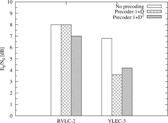
Figure 12.4 summarizes the main results of Section 4.4. It can be seen from Figure 12.4 that the SER performance both of the scheme using RVLC-2 and of that using VLEC-3 can be improved when using appropriate precoders. However, although the precoder of 1 + D2 is optimal for the scheme using RVLC-2, the precoder of 1 + D constitutes a better choice for the scheme using VLEC-3.
Finally, the performance of a three-stage iterative receiver was evaluated in Section 4.4.4. The receiver of Figure 4.41 consists of a channel equalizer, a channel decoder and a source decoder, where the extrinsic information is exchanged among all the three SISO modules, which hence constitutes a joint source–channel decoding and equalization scheme. It was shown in Figure 4.42 that by exploiting the source redundancy in the iterative decoding process, the system’s performance was improved by 2 dB in terms of the Eb/N0 values required for achieving the same SER, when compared with the separate source–channel decoding scheme. The convergence behavior of this scheme was analyzed using EXIT charts in Section 5.7 after we introduced the convergence analysis technique for multi-stage concatenated schemes in Chapter 5.
Figure 12.4: The effects of precoding and those of VLC free distances of df = 2 for the RVLC-2 and df = 3 for the VLEC-3 schemes on the attainable SER performance, when communicating over dispersive AWGN channels, where the Eb/N0 value is the minimum SNR value required for achieving a SER of 10−4. The system model is described in Figures 4.28 and 4.29, where the transmitter is constituted by a VLC encoder as well as a precoder if precoding is employed, and the receiver is constituted by an APP channel equalizer as well as an APP VLC decoder, which performs channel equalization and source decoding iteratively.
12.5 Chapter5: Three-Stage Serially Concatenated Turbo Equalization
Chapter 5 investigated the design of the three-stage serially concatenated turbo MMSE equalization scheme seen in Figure 5.4, which consisted of an inner channel equalizer, a unity-rate recursive intermediate channel code and an outer channel code. Firstly, a brief introduction to SISO MMSE equalization was offered in Section 5.2, followed by an example of conventional two-stage turbo equalization in Section 5.3. The main body of this chapter focussed on the optimization of three-stage turbo equalization schemes by using EXIT-chart analysis.
With the aid of the EXIT modules as proposed in Figure 4.10 of Section 4.2.2, 3D EXIT-chart analysis may be simplified to 2D EXIT analysis as shown in Figures 5.7, 5.8 and 5.9 of Section 5.4.2. It was also shown in Figure 5.8 of Section 5.4.2.1 that, by employing a unity-rate recursive convolutional code as the intermediate constituent code, the three-stage scheme becomes capable of converging to the perfect mutual information point.
Moreover, the outer constituent code was optimized in Section 5.4.2.2 for achieving the lowest possible Eb/N0 convergence threshold. Interestingly, it was observed in Figure 5.8 that relatively weak codes having short memories resulted in a lower convergence threshold than did strong codes having long memories.
Additionally, the activation order of the component decoders was optimized in Section 5.4.2.3 for achieving the convergence at the lowest possible Eb/N0 value, while maintaining a low decoding complexity. It was found in Table 5.2 that by invoking the outer and intermediate decoder of Figure 5.4 more frequently the total number of decoder activations is reduced, resulting in a decreased decoding complexity.
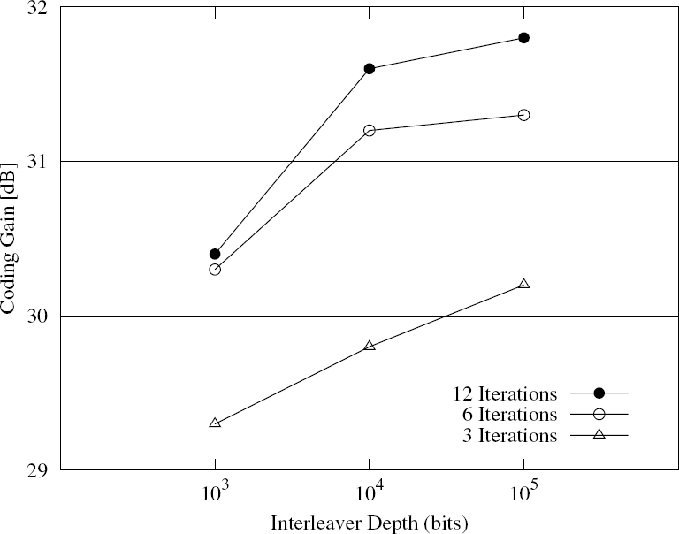
The BER performance of the optimized scheme was evaluated in Section 5.4.3, which verified the EXIT-chart analysis provided in Section 5.4.2. The iterative decoding process was visualized using both 3D and 2D EXIT charts as shown in Figures 5.12–5.15 of Section 5.4.4. Furthermore, the effects of different interleaver block lengths were discussed in Figure 5.16 of Section 5.4.5. Generally, the longer the interleaver length, the more closely the simulated performance matches the EXIT-chart analysis. It was found in Figure 5.16 that an interleaver length of the order of 105 bits is sufficiently high for achieving a good match with the decoding trajectory recorded. Figure 12.5 provided some quantitative results summarized from Section 5.4.5. It can be seen from Figure 12.5 that when the interleaver depth is increased from L = 103 bits to L = 104 bits, a significant coding gain may be attained. Further increasing the interleaver depth to L = 105 bits, however, results in a marginal increase of the coding gain. Naturally, the attainable iteration gain is increased upon increasing the interleaver depth.
In Section 5.5 the maximum achievable information rate of the three-stage turbo equalization scheme of Figure 5.4 was analyzed. Then an IRCC was invoked as the outer constituent code, whose EXIT function was optimized for matching that of the combined module of the inner channel equalizer and the intermediate channel decoder, so that the EXIT-tunnel area between these two EXIT functions was minimized. The Monte Carlo simulation results provided in Figure 5.23 of Section 5.5.4 show that the performance of the resultant scheme is only 0.5 dB away from the channel capacity.
Finally, the employment of non-unity-rate intermediate codes was also considered in Section 5.6. It was shown in Figure5.27 that, as expected, the maximum achievable information rate of such schemes was reduced in comparison with that of the schemes using unity-rate intermediate codes. In contrast, the Eb/N0 convergence threshold may be decreased when only regular convolutional codes are used. A number of optimized serially concatenated codes were obtained, and listed in Table 5.6.
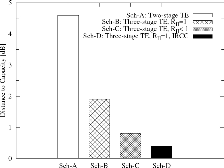
As a summary, Figure 12.6 compares the distance to capacity for the various MMSE turbo equalization schemes discussed in Chapter 5.
In Part II of this book we introduced the novel concept of Irregular Variable Length Coding (IrVLC) and investigated its applications, characteristics and performance in the context of wireless telecommunications. As discussed throughout Part II, IrVLCs encode various components of the source signal with different sets of binary codewords, having a range of appropriately selected lengths. Three particular applications of IrVLCs were investigated in this book, namely joint source and channel coding, EXtrinsic Information Transfer (EXIT)-chart matching and Unequal Error Protection (UEP). These are detailed in the following sections, together with a discussion of our future work.
Figure 12.5: Achievable coding gains at a BER of 10–4 for the three-stage turbo equalization scheme of Figure 5.10 using different interleaver depths. The turbo equalization scheme is constituted by a RSC(2, 1, 2) code as the outer code, a unity-rate RSC(1, 1, 2) code as the intermediate code and an inner MMSE equalizer as described in Section 5.4.
12.6 Chapter 6: Joint Source and Channel Coding
In Chapter 6 we exemplified the application of IrVLCs for the joint source and channel coding of video information. This application was motivated by the observation that Shannon’s source and channel coding separation theorem [133] is invalid in the context of practical video transmission. While source and channel coding can be performed in isolation without imposing any performance loss, if the assumptions discussed in Section 6.1 apply, these conditions are not fulfilled in the case of practical video transmission. We therefore proposed the novel joint source and channel coding scheme of Section 6.2, which employs both Variable-Dimension Vector Quantization (VDVQ) [290] as a special case of Vector Quantization (VQ) [170] and the Reversible Variable-Length Code (RVLC) [276] class of Variable-Length Codes (VLCs).
Here, the employment of VDVQ tiles having a range of dimensions facilitates the efficient representation of both large areas of the video frame that have a low luminance-variance and small areas of high variance, as exemplified in Figure 6.5. Additionally, the employment of RVLC codewords having various lengths facilitates the representation of more frequently occurring VDVQ tiles with the aid of shorter codewords, giving a reduced average codeword length and providing source coding. Furthermore, channel coding is provided by the redundancy that is inherent in the RVLC codewords [276], facilitating an error-correction capability during RVLC decoding. The VDVQ/RVLC video codec advocated therefore employs a joint source and channel coding philosophy.
Figure 12.6: Distance to capacity for the various MMSE turbo equalization schemes of Chapter 5, where Sch-A represents the conventional two-stage turbo equalization scheme of Figure 5.1. Sch-B, Sch-C and Sch-D denote the same three-stage turbo equalization scheme of Figure 5.4, but differ in the channel codes used. Sch-B employs a unity-rate RSC(1, 1, 2) code as the intermediate code and a RSC(2, 1, 2) code as the outer code. Sch-C uses a SCC of SCC-A2, described in Table 5.6, which is constituted by a rate-3/4 RSC(3, 4, 2) code as the intermediate code and a RSC(2, 3, 3) code as the outer code. Sch-D employs the same unity-rate RSC(1, 1, 2) code used in Sch-B as the intermediate code, while using the IRCC described in Section 5.5.3 as the outer code.
In Section 6.3.3 we imposed a number of constraints governing the allocation of the VDVQ tiles and RVLC codebooks in order to represent the various components of the video source frame. More specifically, these code constraints enforced the legitimate tessellation of the VDVQ tiles having a range of dimensions and ensured that the various fractions of the source video frame were encoded using the same number of bits. Since the set of RVLC codewords that can be employed during video encoding varies depending on which component of the source video frame is being encoded, the VDVQ/RVLC video codec can be said to employ IrVLCs.
In the VDVQ/RVLC video codec, the complete set of the above-mentioned code constraints was described by the novel trellis structure of Section 6.3.4, which is reminiscent of a symbol-based VLC trellis [181]. Hence, the employment of this trellis structure facilitated the consideration of all legitimate transmission frame permutations. This fact was exploited in order to perform novel Minimum Mean Square Error (MMSE) VDVQ/RVLC encoding using a variation of the Viterbi algorithm [193], as described in Section 6.4.
Additionally, the employment of the trellis structure during VDVQ/RVLC decoding was shown to guarantee the recovery of legitimate – although not necessarily error-free – video information in Section 6.5. This ensured that useful video information was never discarded, unlike in the conventional video decoders of [273, 274], where a single transmission error may render an entire video frame invalid. A novel modification of the Bahl–Cocke–Jelinek–Raviv (BCJR) algorithm [48] was employed during A Posteriori Probability (APP) Soft-Input Soft-Output (SISO) VDVQ/RVLC decoding in order to facilitate the iterative exchange [278] of extrinsic information with a serially concatenated APP SISO Trellis-Coded Modulation (TCM) [277] decoder, as well as to facilitate the soft MMSE reconstruction of the video sequence. Since the VDVQ/RVLC trellis structure describes the complete set of VDVQ/RVLC-induced code constraints, all of the associated redundancy was beneficially exploited with the aid of the modified BCJR algorithm.
In Section 6.6 the serially concatenated and iteratively decoded VDVQ/RVLC-TCM scheme of Section 6.2 was shown to outperform two suitably designed separate source-and channel-coding benchmarks. This was attributed to the benefits of the VDVQ/RVLC codec described above, which were realized owing to the joint source-and channel-coding philosophy adopted. Indeed, Figure 6.12 shows that the VDVQ/RVLC-TCM scheme was capable of achieving subjectively pleasing video reconstructions having a Peak Signal-to-Noise Ratio (PSNR) of 29.5 dB at a channel Signal-to-Noise Ratio (SNR) that is 1.1 dB lower than that of the VQ-based benchmark [273] and 1.6 dB lower than that of the MPEG4 [158]-based benchmark [274].
12.7 Chapters 7–9: EXIT-Chart Matching
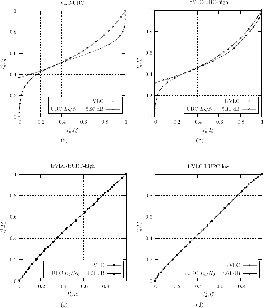
In Chapters 7–9 we considered the application of IrVLCs for EXIT-chart matching. This was motivated by the fact that an open EXIT-chart tunnel was only created for the VDVQ/RVLCTCM scheme of Section 6.2 if the Rayleigh fading channel SNR was in excess of a threshold that was 1.29 dB higher than the channel’s SNR capacity bound, as shown in Figure 12.1. Note that, as described in Section 4.3, an infinitesimally low probability of decoding error can only be achieved if the EXIT-chart tunnel is open and if the iterative decoding trajectory approaches the inner and outer EXIT functions sufficiently closely to facilitate iterative decoding convergence to the (1, 1) point of the EXIT chart. Hence, operation closer than 1.29 dB from the channel’s capacity bound was prevented for the VDVQ/RVLC-TCM scheme, as shown in Figure 6.12. Note that similar discrepancies of 1 dB were obtained for the SBVLC-TCM and BBVLC-TCM schemes of Section 7.3.2, as shown in Figure 12.1. Like the VDVQ/RVLC-TCM scheme of Section 6.2, the SBVLCTCM and BBVLC-TCM schemes employed the serial concatenation and iterative decoding of a VLC-based outer codec with a TCM inner codec, and were not designed using EXIT-chart matching. Furthermore, Figure 12.1 shows that a similar discrepancy of 1.4 dB between the threshold Eb/N0 value and the channel’s attainable capacity bound was obtained for the VLC-URC scheme of Section 9.5.4, which employs Unity-Rate Coding (URC) for the inner codec instead of TCM. Instead of the capacity bound, the channel’s attainable capacity bound is considered in this case, since it is this that imposes the fundamental limit on the VLC-URC scheme’s operation, as described in Section 9.5.3. This is justified, since we will propose a solution to the associated effective throughput loss in Section 12.12, when outlining our future work. The corresponding EXIT chart obtained for the VLCURC scheme of Section 9.5.4 was provided in Figure 9.10, together with those of the other schemes introduced in Section 9.5.4, and these are repeated for convenience in Figure 12.7.
In Section 6.6 we observed that open EXIT-chart tunnels could have been created for channel SNRs that are closer to the channel’s capacity bound if the inverted VDVQ/RVLC EXIT function of Figure 6.11 had offered a better match with the TCM scheme’s EXIT function. More specifically, this would have enabled the EXIT-chart tunnel to remain open and be further narrowed as the channel SNR was reduced towards the channel’s capacity bound. The described observation of Section 6.6 may be explained by the area property of EXIT charts [204], which states that the EXIT-chart area enclosed by the threshold EXIT-chart tunnel is commensurate with the discrepancy between the channel’s capacity bound and the threshold SNR.
Hence, in Section 7.3.2 we demonstrated that the inverted EXIT function of an outer IrVLC codec can be shaped to match with an inner EXIT function. Here, the IrVLC scheme generated particular fractions of the IrVLC-encoded transmission frame using different component VLC codebooks of either the RVLC or the Variable-Length Error-Correction (VLEC) [179] class. We showed that the inverted EXIT function of the corresponding APP SISO IrVLC decoder depends on the specifically chosen fractions of the IrVLC-encoded transmission frame that are generated by each component VLC codebook. More explicitly, the inverted IrVLC EXIT function may be obtained using Equation (7.4), which employs the described fractions as weights during the averaging of the component VLC codebooks’ inverted EXIT functions.
Section 7.3.2 showed that the EXIT-chart matching algorithm of [149] may be employed to design specific parameterizations of the SBIrVLC-TCM and BBIrVLC-TCM schemes detailed in Section 7.2. Here, the algorithm of [149] was employed to shape the inverted IrVLC EXIT functions to match the EXIT function of the serially concatenated TCM codec. This facilitated the creation of open EXIT-chart tunnels at channel Eb/N0 values in excess of a threshold that is 0.5 dB from the channel’s capacity bound, as shown in Table 12.1. This is equal to the 0.5 dB discrepancy shown in Table 12.1 that was obtained when matching the inverted EXIT function of an Irregular Convolutional Code (IrCC) [306] to the TCM EXIT function during the parameterization of the Huffman-IrCC-TCM scheme of Section 7.4.1.
Furthermore, Table 12.1 shows that the open EXIT-chart tunnel of Figure 12.7b was achieved at a similar Eb/N0 discrepancy of 0.54 dB from the channel’s attainable capacity bound for the IrVLC-URC-high arrangement detailed in Section 9.5.4. Note that this scheme employed a serial concatenation of an IrVLC outer codec and a URC inner codec. A URC inner codec was also employed by the IrVLC-URC scheme of Section 8.4. Discrepancies of 0.42 dB and 0.7 dB are shown in Table 12.1 for parameterizations of this scheme that employed IrVLC coding rates of 0.55 and 0.85 respectively. This suggests that an improved EXIT-chart matching was achieved when employing lower IrVLC coding rates, resulting in open EXIT-chart tunnels at channel Eb/N0 values that are closer to the channel’s capacity bound, as shown in Figures 8.12 and 9.9.
Table 12.1: Iterative decoding performance and complexity of the various schemes considered in Chapters 6–9
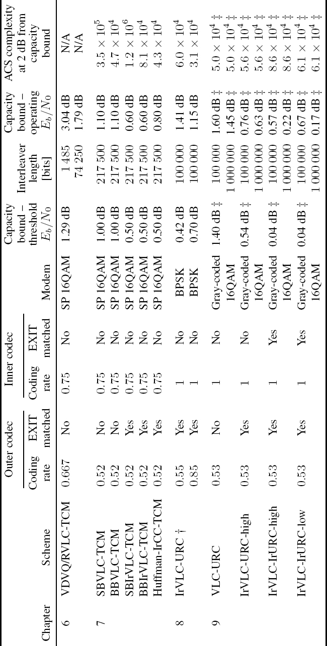
† The IrVLC comprises the component VLEC codebooks {VLECn}22n of Table 8.6, which were designed using the GA of Section 8.3.
‡ The channel’s attainable Eb/N0 capacity bound is employed.
Figure 12.7: EXIT charts for the schemes of Section 9.5.4: (a) VLC-URC arrangement; (b) IrVLC-URC-high arrangement; (c) IrVLC-IrURC-high arrangement; (d) IrVLC-IrURC-low arrangement. The inner EXIT functions are provided for the threshold channel Eb/N0 values, as specified in Table 9.1.
Owing to the aforementioned benefits of EXIT-chart matching, the observed discrepancies in the range of 0.42 dB–0.7 dB are lower than those obtained when EXIT-chart matching was not employed, which are in the range of 1 dB–1.4 dB, as described above.
Figure 12.8: Conventional irregular coding design process.

12.8 Chapter 8: GA-Aided Design of Irregular VLC Components
Chapter 8 showed that our ability to perform EXIT-chart matching and to achieve an open EXIT-chart tunnel at Eb/N0 values that are close to the channel’s capacity bound is commensurate with the degree of diversity in the shapes exhibited by the inverted EXIT functions of the component VLC codebook suite. For this reason, the conventional irregular coding design process strives towards obtaining a component VLC codebook suite having a wide variety of inverted EXIT functions, as shown in Figure 12.8. The component VLEC codebooks employed by the IrVLC schemes of Chapters 7 and 8 were designed using Algorithm 3.3 of Section 3.3. As discussed in Section 8.1, this algorithm attempts to design VLEC codebooks having maximal coding rates that satisfy particular specified distance criteria. However, this algorithm does not facilitate the direct control or prediction of the inverted EXIT function shapes that correspond to the designed VLEC codebooks. Hence, in the conventional irregular coding design process depicted in Figure 12.8, a significant amount of ‘trial-and-error’-based human interaction is required. This involves the design of a high number of candidate component VLEC codebooks, the characterization of their inverted EXIT functions and the selection of a suite having a wide variety of inverted EXIT functions, as exemplified in Chapter 7.
The trial-and-error efforts required to design a suite of IrVLC component codebooks using Algorithm 3.3 of Section 3.3 motivated the design of a novel Genetic Algorithm (GA) for generating the VLEC codebooks of Section 8.3. Unlike Algorithm 3.3 of Section 3.3, this GA was shown to facilitate the direct control and prediction of the inverted EXIT function shapes that result for the designed VLEC codebooks, eliminating the trial-and-error efforts in the irregular coding design process. While maintaining desirable VLEC-encoded bit entropies and IrVLC decoding complexities, the GA of Section 8.3 seeks VLEC codebooks having arbitrary coding rates and Real-Valued Free Distance Metrics (RV-FDMs).
This novel RV-FDM was proposed in Section 8.2 as an alternative to the Integer-Valued Free Distance (IV-FD) lower bound of [179] for the characterization of a VLEC codebook’s error-correction capability. Like the IV-FD lower bound of [179], the RV-FDM considers the minimum number of differing bits in any pair of equal-length legitimate VLEC-encoded bit sequences, characterizing the probability of occurrence for the most likely undetectable transmission error scenario, as described in Section 8.1. However, unlike the IV-FD lower bound, the RV-FDM of Section 8.2 also considers how susceptible the VLEC-encoded bits are to this transmission error scenario. As a result, the RV-FDM exists within the real domain, allowing the comparison of the error-correction capabilities of two VLEC codebooks having equal IV-FD lower bounds. This facilitates its employment within the objective function of the novel GA proposed in Section 8.3.
In Section 8.2, we showed that a VLEC codebook’s RV-FDM affects the number of inflection points appearing in the corresponding inverted EXIT function. More specifically, we showed that high RV-FDMs are associated with ‘S’-shaped inverted EXIT functions having up to two points of inflection, whilst low RV-FDMs result in inverted EXIT functions having no more than one point of inflection. Furthermore, we showed that the inverted EXIT function of a VLEC codebook will reach the top right-hand corner of the EXIT chart if its RV-FDM is at least equal to two [298]. These findings complement the property [204] that the area below an inverted VLEC EXIT function equals the corresponding coding rate. Therefore, since the inverted VLEC EXIT function shape of a VLEC codebook depends on both its coding rate and its RV-FDM, the GA of Section 8.3 facilitates the direct control and prediction of the inverted EXIT function shapes that result for the designed VLEC codebooks.
The employment of both the novel GA of Section 8.3 and Algorithm 3.3 of Section 3.3 to design suites of IrVLC component codebooks was investigated in Section 8.5. The suite of component VLEC codebooks designed in Section 8.5.1 by our novel GA had the wide variety of inverted EXIT functions shown in Figure 8.8. This was obtained by seeking component VLEC codebooks having a wide variety of coding rates and RV-FDMs. In some cases, high RV-FDMs were sought, resulting in ‘S’-shaped inverted EXIT functions having up to two points of inflection, whilst low RV-FDMs were sought for the remaining component VLEC codebooks, which were associated with inverted EXIT functions having no more than one point of inflection. Here, we found that more extreme RV-FDMs could be obtained for VLEC codebooks having lower coding rates. This may be explained by the higher degree of design freedom that is facilitated for lower coding rates owing to the longer codewords that this implies.
When the novel GA of Section 8.3 was employed to design component VLEC codebooks, the trial-and-error approach was not employed. Similarly, no trial and error was employed when Algorithm 3.3 of Section 3.3 was used, facilitating a fair comparison. Instead, a different IV-FD lower bound was sought for each component VLEC codebook designed using Algorithm 3.3 of Section 3.3. However, the resultant component VLEC codebooks were found to have relatively high RV-FDMs and only a limited variety of coding rates, resulting in the limited variety of ‘S’-shaped inverted EXIT functions shown in Figure 8.7.
Owing to its employment of a wider variety of coding rates, and as a benefit of its both high and low RV-FDMs, the suite of component VLEC codebooks designed by our novel GA in Section 8.5.1 was found to be more suitable for use in EXIT-chart matching than that designed using Algorithm 3.3 of Section 3.3. More specifically, open EXIT-chart tunnels could be created for the IrVLC-URC scheme of Section 8.4 at channel Eb/N0 values within 1 dB of the Rayleigh fading channel’s capacity bound for a wide range of effective throughputs, when employing the suite of component VLEC codebooks generated using our GA, as shown in Figure 8.12. In contrast, open EXIT-chart tunnels could only be achieved when employing the suite designed by Algorithm 3.3 of Section 3.3 for a limited range of effective throughputs and within a significantly higher margin of 4.4 dB from the Eb/N0 capacity bound. This confirmed the observation that our ability to perform EXIT-chart matching depends on how much variety is exhibited within the inverted EXIT functions of the suite of component VLEC codebooks.
However, regardless of the component VLEC codebook suite employed, we observed in Section 8.5.4 that the inverted IrVLC EXIT function can only be matched to the EXIT functions of a regular inner codec with limited accuracy. This is because inverted outer EXIT functions are constrained to starting from the (0, 0) point of the EXIT chart, while the inner chart, EXIT functions typically emerge from a relatively high point along the Iie axis of the EXIT chart, as described in Section 4.2. As a result, we cannot create an arbitrarily narrow open EXIT-chart tunnel. Instead, a lower bound is imposed upon the enclosed EXIT-chart area and, hence, upon the discrepancy between the threshold Eb/N0 value and the channel’s capacity bound, owing to the area property of EXIT charts [204].
12.9 Chapter 9: Joint EXIT-Chart Matching of IRVLCs and IRURCs
The above-mentioned findings motivated the introduction of novel Irregular Unity-Rate Codes (IrURCs) in Chapter 9, which encode different fractions of the transmission frame using different component URCs, having various EXIT functions. In analogy with those of IrVLCs and IrCCs, IrURC EXIT functions may be shaped by specifically selecting the fraction of the transmission frame that is encoded by each component URC. In this way, the IrURC EXIT function may be shaped to emerge from a point on the EXIT chart’s Iie axis that is closer to the inverted outer EXIT function’s starting point of (0, 0).
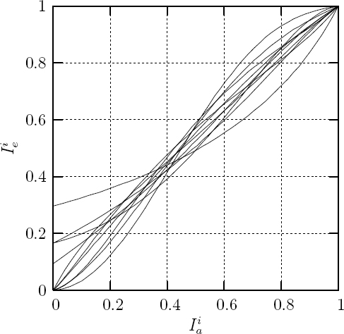
The serial concatenation and iterative decoding of an IrVLC outer codec with an IrURC inner codec was demonstrated in Section 9.4. Here, the IrVLC’s suite of component VLEC codebooks was designed using the GA of Section 8.3 in order to generate the required diversity of inverted EXIT function shapes shown in Figure 9.5 and repeated for convenience in Figure 12.9. In contrast, the EXIT functions shown in Figure 9.7 and repeated for convenience in Figure 12.10 were obtained by selecting the IrURC’s suite of component URCs from a large number of candidates, as described in Section 9.5.2. In Section 9.3
Figure 12.9: Inverted EXIT functions for the component VLEC codebooks employed by the IrVLC-IrURC-high and IrVLC-IrURC-low arrangements of Section 9.5.4.

Figure 12.10: EXIT functions corresponding to a Gray-coded 16QAM-modulated Rayleigh fading channel SNR of 8 dB for the component URC codes employed by the IrVLC-IrURChigh and IrVLC-IrURC-low arrangements of Section 9.5.4.
we proposed a novel method for jointly matching the EXIT functions of the two serially concatenated irregular codecs. This method iteratively applies the EXIT-chart matching algorithm of [149] to alternately match the outer EXIT function to the inner and vice versa, simultaneously seeking the highest coding rate that offers an open EXIT-chart tunnel. Note however, that the novel modification of Section 9.2 was required in order to allow the EXIT-chart matching of the IrURC EXIT function, since all component URCs have the same unity coding rate. The joint EXIT-chart matching algorithm of Section 9.3 was shown to be able to exploit the increased degree of design freedom that is afforded by employing two irregular codecs in order to create an EXIT-chart tunnel that is narrow at all points along its length. This facilitated the creation of the marginally open EXIT-chart tunnels shown in Figures 12.7c and 12.7d for the IrVLC-IrURC-high and IrVLC-IrURC-low arrangements of Section 9.5.4, respectively. Owing to the area property of EXIT charts, these were obtained at Eb/N0 values that were just 0.04 dB from the channel’s attainable capacity bound, as shown in Figure 12.1.
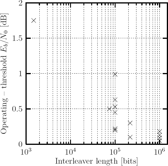
Note that an open EXIT-chart tunnel implies that iterative decoding convergence to an infinitesimally low probability of error can be achieved, provided that the iterative decoding trajectory approaches the inner and outer EXIT functions sufficiently closely, as described in Section 4.3. However, throughout this monograph we found that high-quality reconstructions could not be achieved at the threshold Eb/N0 values, where the EXIT-chart tunnels open. This is due to the BCJR algorithm’s assumption [48] that all correlation within the LLR frames exchanged by the APP SISO decoders is successfully mitigated by the intermediary interleavers. If this is not the case, the iterative decoding trajectory will not match perfectly with the inner and outer EXIT functions and the tunnel must be further widened before the trajectory can reach the top right-hand corner of the EXIT chart, which is associated with an infinitesimally low probability of error, as described in Section 4.3. Since the interleaver’s ability to mitigate the correlation is proportional to its length, longer interleavers can be expected to yield lower discrepancies between the Eb/N0 value at which the EXIT-chart tunnel opens and that at which it is sufficiently widened to facilitate a high reconstruction quality. Indeed, this relationship may be observed in Figure 12.11, which provides a scatter plot of the discrepancies and interleaver lengths given in Table 12.1, as will be detailed in our forthcoming discussions.
Figure 12.11: Scatter plot of the interleaver lengths provided in Table 12.1 and the corresponding discrepancies between the Eb/N0 value at which EXIT chart tunnel opens and that at which it is sufficiently widened to facilitate a high reconstruction quality.
In Section 6.6 we had characterized the discrepancy between the threshold Eb/N0 value at which an open EXIT-chart tunnel could be created for the VDVQ/RVLC-TCM video transmission scheme and the operating Eb/N0 value at which it could achieve a high-quality reconstruction having a Peak Signal-to-Noise Ratio (PSNR) of 29.5 dB. This discrepancy was found to be 1.75 dB when the interleaver length was equal to that of a single encoded video frame, namely 1 485 bits, as shown in Table 12.1. In contrast, when 50 encoded video frames were concatenated to give an interleaver length of 74 250 bits, the discrepancy was reduced to just 0.5 dB, facilitating operation at 1.79 dB from the channel’s Eb/N0 capacity bound. However, in Section 6.6 this scheme was shown to incur a 5 s latency, since the video frame rate was 10 fps and because all 50 frames must be received before they can be deinterleaved.
The discrepancy between the threshold Eb/N0 value at which an open EXIT-chart tunnel could be created for the arrangements of Section 9.5.4 and the operating Eb/N0 value at which they could achieve a BER of 10−5 was characterized in Section 9.6. When a 100 000 bit interleaver was employed, the discrepancies for the VLC-URC and IrVLC-URC-high arrangements were found to be 0.2 dB and 0.22 dB respectively, as shown in Table 12.1.
However, these discrepancies were reduced to 0.05 dB and 0.09 dB respectively when we employed a longer interleaver, having a length of 1 000 000 bits. Larger discrepancies were observed for the IrVLC-IrURC-high and IrVLC-IrURC-low arrangements, owing to their narrow EXIT-chart tunnels, as discussed in Section 9.6. These were 0.53 dB and 0.67 dB respectively when the 100 000-bit interleaver was employed, as compared with 0.18 dB and 0.13 dB respectively when the 1 000 000-bit interleaver was employed. Note that the IrVLC-IrURC-low arrangement using the 1 000 000 bit interleaver could achieve a BER of less than 10−5 for Eb/N0 in excess of a limit that was just 0.17 dB from the channel’s attainable capacity bound, as shown in Table 12.1. This is comparable with the 0.13 dB discrepancy demonstrated for Irregular Low-Density Parity Check (IrLDPC) codes [147, 313] and superior to the 0.25 dB discrepancy found for irregular turbo codes [148].
In Section 7.4 we showed that the SBVLC-, BBVLC-, SBIrVLC-and BBIrVLC-TCM schemes using a 217 500-bit interleaver could achieve a high-quality source sample reconstruction SNR of 20 dB for Eb/N0 values in excess of a limit that was 0.1 dB from the threshold at which an open EXIT-chart tunnel was created, as shown in Table 12.1. However, in the case of the Huffman-IrCC-TCM scheme of Section 7.4.1, the corresponding discrepancy was equal to the higher value of 0.3 dB. This was explained in Section 7.4.3 by the relatively high sensitivity of the APP SISO IrCC decoder to any residual correlation within the iteratively exchanged LLRs that was insufficiently mitigated by the 217 500-bit interleaver. This resulted in the poor correlation between the iterative decoding trajectory and the inverted IrCC EXIT function. More specifically, we concluded that an APP SISO IrCC decoder’s sensitivity to this correlation increases if its coding rate is reduced or if, in particular, we increase its coding memory. Hence, the high sensitivity of the Huffman-IrCC-TCM scheme’s APP SISO IrCC decoder was attributed to its relatively high coding memory of 4.
Section 7.4.3 also concluded that an APP SISO VLC decoder’s sensitivity to the aforementioned correlation depends only on its coding rate. Indeed, in Section 8.6 the APP SISO IrVLC decoder’s sensitivity to this extrinsic information correlation was found to increase as the IrVLC coding rate was reduced. As shown in Table 12.1, the IrVLC-URC scheme of Section 8.4 using a 100 000-bit interleaver and an IrVLC coding rate of 0.85 could achieve a BER of less than 10−5 for Eb/N0 values in excess of a limit that was 0.45 dB from the threshold at which an open EXIT-chart tunnel was created. However, this discrepancy grew to 0.99 dB when the IrVLC coding rate was reduced to 0.55, as shown in Table 12.1.
Throughout this book we have considered receivers in which soft information is iteratively exchanged between APP SISO decoders and in which a final hard decision is made by a MAP sequence estimator. These components of the receiver apply the BCJR algorithm [48] and the Viterbi algorithm [193] to suitably designed trellises [141, 180]. These require only Add, Compare and Select (ACS) operations if all calculations are performed in the logarithmic probability domain and if a lookup table is employed for correcting the Jacobian approximation [296]. Since each individual ACS operation requires the same resources in a systolic-array-based chip, the number of ACS operations performed by a receiver may be employed to characterize the complexity/area/speed trade-off required for its implementation.
In Section 7.4 we introduced the novel plot of Figure 7.12 for characterizing the iterative decoding complexity of a receiver. This plot provides the average number of ACS operations required per source symbol to achieve particular reconstruction qualities as a function of the channel’s Eb/N0 value. This plot, as well as those of Figures 7.13, 8.17, 8.18 and 9.12, showed that particular reconstruction qualities can be achieved with lower complexities as the channel’s Eb/N0 value is increased. This may be explained by the associated widening of the open EXIT-chart tunnel, requiring fewer decoding iterations for the iterative decoding trajectory to reach the particular point on the EXIT chart that is associated with the reconstruction quality considered.
Additionally, Figures 7.12 and 7.13 showed that lower complexities may be maintained, provided that lower reconstruction qualities can be tolerated, since fewer decoding iterations are required for the iterative decoding trajectory to reach the particular point on the EXIT chart that is associated with a lower reconstruction quality. However, Section 7.4.5 observed that, in the approach of iterative decoding convergence, large reconstruction quality gains are obtained for relatively small amounts of additional computational complexity. We concluded that if the channel Eb/N0 value is sufficiently high as to create an open EXIT-chart tunnel, then we can typically justify the computational complexity required for the iterative decoding trajectory to reach the (1, 1) point of the EXIT chart, owing to the infinitesimally low probability of error that results.
In Sections 7.4.5, 8.6 and 9.5.4 we showed that outer APP SISO decoding and MAP sequence estimation are typically associated with significantly higher computational complexities than is inner APP SISO decoding. In the most extreme case considered in this volume, the outer decoders of the SBVLC-and SBIrVLC-TCM schemes of Section 7.2 accounted for about 97% of the ACS operations employed per source sample. In contrast, the outer decoders of the Huffman-IrCC-TCM scheme of Section 7.4.1 were responsible for about 60% of the iterative decoding complexity, in the most balanced case considered.
In Table 12.1, we provide the average number of ACS operations required per source symbol to achieve high-quality reconstructions at an Eb/N0 value that is 2 dB from the channel’s capacity bound for each of the schemes considered in Sections 7.2 and 8.5.4. Additionally, for the schemes of Section 9.6, the complexity at an Eb/N0 value that is 2 dB from the channel’s attainable capacity bound is provided in Table 12.1. Furthermore, Figure 12.12 plots the complexities of the aforementioned schemes for a range of Eb/N0 discrepancies from the capacity bounds. While the complexities shown in Table 12.1 and Figure 12.12 for the schemes of Section 7.2 are associated with obtaining a high-quality source sample reconstruction SNR of 20 dB, those provided for the schemes of Sections 8.5.4 and 9.6 are associated with achieving a BER of 10 −5. The comparison of the described complexities is fair, since each of the schemes considered in Chapters 7–9 facilitates the transmission of 16-ary source symbols over an uncorrelated narrowband Rayleigh fading channel. Furthermore, in all cases the source symbols have the probabilities of occurrence that result from the Lloyd–Max quantization [164, 165] of Gaussian distributed source samples, as described in Section 7.2.1.
Note that Figure 12.12 illustrates the discrepancies between the channel’s appropriate capacity bounds and the Eb/N0 values above which the schemes considered in Chapters 7–9 may achieve high-quality reconstructions, confirming the discrepancies provided in Table 12.1. Furthermore, at high discrepancies from the channel’s Eb/N0 capacity bounds, Figure 12.12 shows that similar iterative decoding complexities may be observed for the BBVLC-, BBIrVLC-and Huffman-IrCC-TCM schemes of Section 7.2 as well as for each scheme introduced in Sections 8.5.4 and 9.6. Indeed, the corresponding ACS counts provided in Table 12.1 can be seen to have similar values in the range of [3.1 × 10⁴, 8.6 × 10⁴]. This similarity may be explained because all of these schemes employ bit-based trellises [141, 180] as the basis of their outer APP SISO decoders and MAP sequence estimators. In contrast, the SBVLC-and SBIrVLC-TCM schemes of Section 7.2 employed the symbol-based VLC trellis of [181] as the basis of their APP SISO decoders. For these schemes, Table 12.1 provides ACS operation counts of 3.5 × 10⁵ and 1.2 × 10⁶ respectively, which are significantly higher than those provided for the schemes employing bit-based trellises, as illustrated in Figure 12.12. This increased complexity may be attributed to the number of trellis transitions that are employed in symbol-based VLC trellises, which is typically significantly higher than the number employed in their bit-based equivalents, as described in Section 3.4.
Figure 12.12: Average number of ACS operations per source symbol required to achieve high-quality reconstructions at a range of Eb/N0 discrepancies from the appropriate capacity bounds for the schemes of Chapters 7-9.
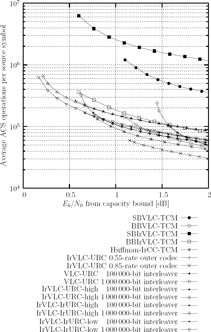
The computational complexities provided in Figure 12.12 for the IrVLC-URC arrangement of Section 8.5.4 having an IrVLC coding rate of 0.85 can be seen to be lower than that associated with an IrVLC coding rate of 0.55. This may be explained by the higher number of bit-based trellis transitions that are required to represent the longer codewords of the 0.55rate IrVLC, as discussed in Section 8.6. For this reason, we can expect lower computational complexities to be associated with VLCs and IrVLCs having higher coding rates in general. This is confirmed by the average numbers of ACS operations performed per source symbol that are provided for VLEC codebooks having various coding rates in Figures 8.7–8.10 and 9.5. These figures additionally show that VLEC codebooks having relatively low RV-FDMs are also associated with low computational complexities. This was exploited during the design of the IrVLC-IrURC-low arrangement of Section 9.5.4. More specifically, the novel modification of the EXIT-chart matching algorithm [149] of Section 9.2 was employed jointly to perform EXIT-chart matching while seeking a reduced IrVLC computational complexity by invoking component VLEC codebooks having a low RV-FDM. As a result, in Table 12.1 the computational complexity of the IrVLC-IrURC-low arrangement can be seen to be 25% lower than that of the IrVLC-IrURC-high arrangement, which was designed without seeking a reduced IrVLC computational complexity. Note that a reduced computational complexity could not be achieved when the IrVLC’s EXIT function was matched to that of a regular URC, as discussed in Section 9.5.4. This was found to be because, unlike the ‘S’-shaped inverted EXIT functions of the component VLEC codebooks having a high RV-FDM, those associated with a low RV-FDM do not rise rapidly enough to match with the URC EXIT function, which starts from a high point along the EXIT chart’s Iei axis.
In Section 7.2.1 we showed that the number of transitions employed by a symbol-based VLC trellis, and hence its computational complexity and memory requirement, scales with the square of the number of source symbols that it simultaneously decodes. For this reason, the total computational complexity and memory requirement can be reduced by decomposing each source symbol frame into sub-frames, which are decoded separately. However, owing to the nature of VLCs, the lengths of VLC-encoded transmission sub-frames typically vary from frame to frame. In order to facilitate their decoding in the receiver, the transmitter must convey the lengths of the sub-frames as explicit side information, which should be protected using a low-rate channel code owing to its error-sensitive nature. Hence, the choice of how many sub-frames to employ is a trade-off between the amount of side information required and the computational complexity, as well as the memory requirements per source symbol. Note that the complexities provided in Table 12.1 and Figure 12.12 for the SBVLC-and SBIrVLC-TCM schemes of Section 7.2 are therefore specific to the particular considered case, in which each source symbol sub-frame comprised 100 symbols. In this arrangement, the required side information was found to account for 4% of the total information conveyed in Section 7.3.
In contrast, Section 7.2.1 showed that the number of transitions per source symbol employed by a bit-based trellis is independent of the number of source symbols that it simultaneously decodes. Hence, the total computational complexity and memory requirement cannot be reduced by decomposing each source symbol frame into sub-frames in this case. However, the memory required to decode each source symbol sub-frame will be reduced if more sub-frames are employed. If the sub-frames are decoded sequentially, this memory can be reused for each sub-frame and a lower-cost implementation will result. By contrast, the amount of memory required by an implementation that decodes all sub-frames concurrently will not be affected by the number of sub-frames employed.
In the schemes of Sections 8.5.4 and 9.6, the amount of side information required was significantly reduced by employing just a single source symbol sub-frame for each IrVLC component code. Using this approach, we found that less side information was required when a longer interleaver was employed, as described in Section 9.6. Indeed, the required side information was reduced to just 0.006% of the total information conveyed when a 1 000 000bit interleaver was employed.
12.10 Chapter 10: Iteratively Decoded VLC Space–Time Coded Modulation
In this chapter an iteratively decoded variable-length space–time coded modulation design was proposed. The joint design of source coding, space–time coded modulation and iterative decoding was shown to achieve both spatial diversity and multiplexing gain, as well as coding and iteration gains at the same time. The variable-length structure of the individual codewords mapped to the maximum of Nt transmit antennas imposes no synchronization and error-propagation problems. The convergence properties of the proposed VL-STCMID scheme were analyzed using 3D symbol-based EXIT charts as well as 2D EXIT-chart projections. A significant iteration gain was achieved by the VL-STCM-ID scheme, which hence outperformed both the non-iterative VL-STCM scheme and the FL-STCM benchmark with the aid of Nt unity-rate recursive feedback precoders. The VL-STCM-ID scheme attains a near-MIMO channel capacity performance.
12.11 Chapter 11: Iterative Detection of Three-Stage Concatenated IrVLCFFH-MFSK
In this chapter we investigated a serially concatenated IrvLC/FFH-MFSK transceiver operating in a Rayleigh fading channel, when the transmitted signal was also corrupted by PBNJ. Our EXIT-chart analysis demonstrated that a two-stage concatenated FFH-MFSK requires the employment of an additional unity-rate precoder for the sake of making the channel appear recursive. In order to ensure near-capacity operation, the IrVLC codec was specifically designed to ensure that the inverted EXIT curve of the IrVLC decoder matches the EXIT curve of the inner decoder. In this way, an open EXIT-chart tunnel may be created even at low SNR values, providing source-correlation-dependent additional performance gains of up to 1.1 dB over the regular VLC-based benchmark scheme. Since the employment of the VLC involves non-identical occurrence probabilities for the source symbols, it is not possible to provide a comparison of the proposed scheme with the state of the art in the context of coded FFH-MFSK, which traditionally employs equiprobable source symbols or bits. However, we have provided a comparison of the IrVLC scheme with a VLC scheme dispensing with the precoder; consequently we noted that the precoder-aided schemes yield an Eb/N0 gain in excess of 7 dB over the system dispensing with the precoder, which suffers from an error floor when jamming is severe.
Moreover, we demonstrated that the three-stage concatenation involving the demodulator, the rate-1 decoder and the outer IrVLC decoder yields superior performance compared with the two-stage concatenation of the rate-1 decoder and the outer decoder. Naturally, the three-stage scheme imposes a higher complexity. By contrast, we found that a precoder of memory 1 is more suitable for the three-stage IrVLC scheme, while the two-stage scheme requires a precoder of memory 3; thus the memory-3 rate-1 decoder imposes a somewhat higher complexity than does its memory-1 counterpart.
In conclusion, the precoder-aided FFH-MFSK-VLC scheme constitutes a moderate-complexity design option, which can be employed in systems communicating through channels contaminated by PBNJ for transmission of joint source and channel encoded audio or video signals. If a higher complexity can be afforded, the IrVLC-based scheme offers additional performance improvements. In our future work we will investigate more sophisticated three-stage iterative decoding, exchanging extrinsic information amongst the demodulator, the rate-1 decoder and the outer decoder.
12.12 Future Work
As shown in Table 12.1, the schemes of Sections 6.2 and 7.2 employed a RTCM = 3/4-rate TCM inner codec together with Set Partitioned (SP) MTCM = 16-ary Quadrature Amplitude Modulation (16QAM) [277] to facilitate transmissions over an uncorrelated narrowband Rayleigh fading channel. However, in these schemes the maximum effective throughput is limited to RTCM · log2(MTCM) = 3 bits per channel use. Owing to the less-than-unity TCM coding rate, an effective throughput loss occurs for high channel Eb/N0 values, where the capacity of the 16QAM modulated channel will exceed the maximum effective throughput of 3 bits per channel use and will approach log2(MTCM) = 4 bits per channel use.
This motivated the employment of an inner URC codec in Section 8.4, which used MBPSK = 2 Binary Phase-Shift Keying (BPSK) [300] to facilitate transmissions over an uncorrelated narrowband Rayleigh fading channel, as shown in Figure 12.1. Here, the maximum effective throughput was equal to the maximum capacity of log2(MBPSK) = 1 bit per channel use and no effective throughput loss was incurred. Indeed, the areas beneath the URC EXIT functions provided in Figure 8.13 were found to be equal to the corresponding channel capacities, as predicted by the area property of EXIT charts [204].
In the scheme of Section 9.4 we opted for employing a URC-based inner codec together with MQAM = 16QAM instead of BPSK, since this facilitates a higher maximum effective throughput of log2(MQAM) = 4 bits per channel use. In Section 9.5.2 we showed that the receiver of Figure 9.3 would benefit from the iterative extrinsic information exchange of the 16QAM demodulator and the inner APP SISO decoder. However, for the sake of obtaining an implementational and computational complexity saving, the receiver of Figure 9.3 employed only the ‘one-shot’ activation of the 16QAM demodulator. However, as a result, when multiplied by log2(MQAM) = 4the average area beneath the URC EXIT functions exemplified in Figure 9.7 did not equal the corresponding channel capacities.
Figure 12.13: Schematic of the IrVLC-SBIrURC scheme.

In Section 9.5.3 we defined the attainable capacity of a channel having a particular Eb/N0 value as being equal to the average area beneath the corresponding URC EXIT functions, multiplied by log2(MQAM) = 4. We showed that the channel’s attainable capacity represents an upper bound to the maximum effective throughput for which an open EXIT-chart tunnel can be achieved. This is because a scheme’s effective throughput may be approximated by multiplying the area beneath the inverted outer EXIT function by log2(MQAM) = 4 [204]. Since this area must be lower than that beneath the inner EXIT function in order for an open EXIT-chart tunnel to be facilitated, iterative decoding convergence to an infinitesimally low probability of error is prevented when the effective throughput is higher than the channel’s attainable capacity. The discrepancy between the channel’s capacity and its attainable capacity therefore imposes an effective throughput loss.
Section 9.5.2 showed that this effective throughput loss was minimized by employing Gray-coded 16QAM [311], since the corresponding EXIT function of Figure 9.8 is optimized to emerge from the highest possible point on the EXIT chart’s Im axis. As shown in Figure 9.9, the effective throughput loss resulted in a discrepancy of 0.29 dB between the channel’s Eb/N0 capacity bound and its attainable capacity bound. Hence, the 0.17 dB discrepancy between the channel’s attainable capacity bound and the Eb/N0 value at which the IrVLC-IrURC-low arrangement could achieve a BER of 10−5 that is shown in Table 12.1 represents a 0.46 dB discrepancy from the channel’s capacity bound.
In this section we propose a method for mitigating the effective throughput loss of the IrVLC-IrURC scheme detailed in Section 9.4. However, this solution does not employ iterative extrinsic information exchange between the 16QAM demodulator and the inner APP SISO decoder. Instead, the benefit of iterative demodulation is mitigated by replacing the bit-based IrURC inner codec of Figure 9.3 with a Symbol-Based Irregular Unity-Rate Code (SBIrURC). Unlike a bit-based IrURC, this SBIrURC can directly employ the symbol probabilities obtained for the demodulator’s M QAM = 16constellation points without first converting them into sets of log2(MQAM) = 4 bit probabilities. We refer to this proposed solution as the IrVLC-SBIrURC scheme and Figure 12.13 provides its schematic, which is reminiscent of the IrVLC-IrURC schematic provided in Figure 9.3.
In the IrVLC-SBIrURC scheme of Figure 12.13, IrVLC encoding, APP SISO decoding and MAP sequence estimation are performed in exactly the same way as in the IrVLC-IrURC scheme of Figure 9.3. Furthermore, the source symbol frames, the transmission frame u and the LLR frames Loa(u) as well as Lop(u) are composed of N sub-frames, as in the IrVLC-IrURC scheme of Figure 9.3. Likewise, the interleaved transmission frame u′and the LLR frames Lia(u′) as well as Lip(u′) are composed of R sub-frames, as before. Additionally, a iterative decoding is performed as in the IrVLC-IrURC receiver of Figure 9.3, with the subtraction of the a priori LLR frames from the a posteriori LLR frames and the interleaving π of the resultant extrinsic LLR frames, as shown in Figure 12.13. Finally, as in the IrVLC-IrURC scheme of Figure 9.3, the outer and inner EXIT functions of the IrVLC-SBIrURC scheme may be shaped by specifically selecting the fractions, {αn}Nn = 1 and {αr}Rr = 1 of the frames u and u′ that are composed by the sub-frames {un}Nn = 1 and {ur}Rr = 1 respectively. The IrVLC-SBIrURC scheme of Figure 12.13 differs from the IrVLC-IrURC scheme of Figure 9.3 in terms of the operation of the irregular inner codec and the modem.
In the IrVLC-SBIrURC transmitter of Figure 12.13, each interleaved transmission sub-frame u′r is decomposed into sets of log2(MQAM) = 4 consecutive bits, which are converted into MQAM = 16-ary symbol values. In analogy with the IrVLC-IrURC scheme of Figure 9.3, the MQAM = 16-ary symbol values corresponding to each interleaved transmission sub-frame u′r are encoded using a Symbol-Based Unity-Rate Code (SBURC) having a different symbol-based Linear Feedback Shift Register (LFSR) design. For example, these LFSRs could employ the designs of Figure 9.6 if they were modified to employ modulo-16 additions and memory elements. Following SBURC encoding in the IrVLC-SBIrURC transmitter, the sub-frame vr of SBURC-encoded MQAM = 16-ary symbol values is obtained, as shown in Figure 12.13.
In the IrVLC-SBIrURC transmitter of Figure 12.13, the MQAM = 16-ary symbol values of each SBURC-encoded sub-frame vr are mapped to MQAM = 16QAM constellation points in order to generate the corresponding channel input symbol sub-frame xr. However, a different mapping scheme may be employed for each SBURC-encoded sub-frame vr, facilitating irregular modulation, as shown in Figure 12.13. Suitable MQAM = 16QAM mapping schemes include Gray coding [300], SP [277], Modified Set Partitioning (MSP) [358], the mixed mapping of [358], the Maximum Squared Euclidean Weight (MSEW) mapping of [359] and the M16a and M16r mappings of [360].
Following modulation, the resultant channel input symbol sub-frames {xr}Rr = 1 are concatenated in order to obtain the channel input symbol frame x. This is transmitted over an uncorrelated narrowband Rayleigh fading channel and received as the channel output symbol frame y, as shown in Figure 12.13. In the IrVLC-SBIrURC receiver of Figure 12.13, the channel output symbol frame y is decomposed into R sub-frames {yr}Rr = 1, each of which is interpreted by a different MQAM = 16QAM demodulator. More specifically, for each channel output symbol, the demodulators determine the probability that the corresponding channel input symbol conveyed each of the MQAM = 16 constellation points. Following this, the MQAM = 16probabilities associated with each channel output symbol in the sub-frame yr are provided as a priori information to the corresponding APP SISO SBURC decoder in the form of the logarithmic a priori probability sub-frame Lia((vr), as shown in Figure 12.13.
In the IrVLC-SBIrURC receiver of Figure 12.13, each a priori LLR sub-frame Lia(u′r) is decomposed into sets of log2(MQAM) = 4consecutive LLRs, which are converted into sets of MQAM = 16log-APPs in a manner similar to that of TCM [277]. The TCM symbol-based trellis [277] is employed to interpret these log-APPs, together with those of the log-APP sub-frame Lia(vr) provided by the demodulator. Here, the BCJR algorithm [48] is employed to determine sets of MQAM = 16 a posteriori log-APPs, which are converted into sets of log2(MQAM) = 4LLRs for the a posteriori LLR sub-frame Lip(u′r).
In addition to mitigating the effective throughput loss of the IrVLC-IrURC scheme of Figure 9.3, the IrVLC-SBIrURC scheme facilitates a higher degree of design freedom, owing to its employment of irregular modulation. While a different EXIT function may be obtained for each component URC code in the IrVLC-IrURC scheme of Figure 9.3, the IrVLC-SBIrURC scheme benefits from a different EXIT function for each combination of the component URC code and component 16QAM mapping. As a result, a greater variety of inner EXIT function shapes can be obtained, facilitating the improved joint matching of the inner and outer EXIT functions, as described in Section 9.3.
Note, however, that APP SISO SBURC decoders are associated with a significantly higher computational complexity than are their bit-based equivalents, owing to the significantly higher number of trellis transitions that they employ [277]. For example, a MQAM = 16ary SBURC employing just one memory element in its LFSR is associated with a trellis that employs MQAM = 16 transitions from each of MQAM = 16 states for each set of log2(MQAM) = 4 bits. By contrast, the equivalent bit-based URC employs two transitions from each of two states for each bit. We can therefore expect the APP SISO decoder of the described SBURC to have a 16 times higher complexity than that of the equivalent bit-based URC. With reference to Table 9.7, we may observe that a 16 times increase in the inner APP SISO decoder’s complexity would cause it to eclipse that of the outer APP SISO decoder and dominate the iterative decoding complexity. This could be countered, however, by employing the novel modification to the EXIT-chart matching algorithm [149] of Section 9.2 for the sake of jointly performing EXIT chart matching and seeking a reduced SBIrURC computational complexity.
In the light of these discussions, our future work will consider the design and characterization of the IrVLC-SBIrURC scheme of Figure 9.3.
12.13 Closing Remarks
Throughout this book we have introduced novel IrVLC-aided wireless telecommunication schemes and methodologies for their design, in the pursuit of near-capacity operation. In Chapter 6 we developed a scheme without making any particular effort to facilitate its near-capacity operation. Here, EXIT-chart analysis was only employed in order to quantify how close to capacity the scheme could operate. By contrast, EXIT-chart analysis was employed as an integral part of the design process in Chapter 7. More specifically, EXIT-chart matching was employed to shape the IrVLC EXIT function to match that of the serially concatenated inner codec and hence to facilitate near-capacity operation. Further gains were achieved in Chapter 8 by challenging the conventional irregular coding design process of Figure 12.8. Instead of selecting a suite of IrVLC components having a wide variety of EXIT function shapes from a set of many candidates, a suite was directly designed using the RV-FDM of Section 8.2 and the GA of Section 8.3. In Chapter 9 we invoked an irregular inner codec to complement the IrVLC, facilitating a higher degree of design freedom. This was exploited by the joint EXIT-chart matching algorithm of Section 9.3 in order to match the IrVLC and inner EXIT functions to each other, facilitating even ‘nearer-to-capacity’ operation. Finally, in Section 12.12 outlining our future work, we proposed a method for mitigating the effective throughput loss that was associated with the scheme of Chapter 9, as well as for facilitating the employment of irregular modulation and for providing an even higher degree of design freedom. With these benefits, we may expect to achieve ‘very-near-capacity’ operation.