Chapter 9
Joint EXIT-Chart Matching of Irregular Variable-Length Coding and Irregular Unity-Rate Coding1
9.1 Introduction
In Chapters 7 and 8 we characterized the serial concatenation [275] of an irregular outer codec with a regular inner codec, as proposed in [149]. Whilst Chapters 7 and 8 employed different regular inner codecs, they both employed Irregular Variable-Length Coding (IrVLC) as their irregular outer codec. This scheme comprises N component Variable-Length Error-Correction (VLEC) codebooks [179] {VLECn}Nn=1 having a variety of coding rates {R(VLECn)}Nn=1, as described in Section 5.5. At the transmitter, each component VLEC codebook VLECn is invoked to generate a specific fraction of the transmission frame, given by the component’s weight αn, where we have
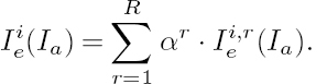
At the receiver, an inner A Posteriori Probability (APP) Soft-Input Soft-Output (SISO) decoder [292] iteratively exchanges extrinsic information with the APP SISO IrVLC decoder [278], as described in Section 4.1. As usual, the EXtrinsic Information Transfer (EXIT) function [294] Iei(Ia) of the inner APP SISO decoder may be employed to characterize its operation. Similarly, the operation of the APP SISO IrVLC decoder may be characterized by its inverted EXIT function Iao(Ie). As described in Section 5.5, this may be obtained [149] as a weighted average of the inverted EXIT functions {Iao,n(Ie)}Nn=1 corresponding to the N component VLEC codebooks, according to

As demonstrated in Chapters 7 and 8, the EXIT-chart matching algorithm of [149] is capable of shaping the inverted IrVLC EXIT function Iao(Ie) by specifically selecting the fractions {αn}Nn=1, subject to the constraints of Equations (9.1) and (9.2), and to

where RIrVLC is a specified target IrVLC coding rate. In this way, the inverted IrVLC EXIT function Iao(Ie) may be shaped so that it does not intersect with an inner EXIT function that corresponds to a near-capacity channel Signal-to-Noise Ratio (SNR). Note that the resultant open EXIT-chart tunnel [267] implies that iterative decoding convergence to an infinitesimally low probability of error can be achieved, provided that the iterative decoding trajectory approaches the inner and outer EXIT functions sufficiently closely, as described in Section 4.3.
However, it was found in Figure 8.13 of Section 8.5.4 that the accuracy of EXIT-chart matching using the algorithm of [149] is limited by the typically high starting point of the EXIT functions Iei(Ia) of the inner codes along the EXIT chart’s Iei axis. This is because the inverted IrVLC EXIT function Iao(Ie) is constrained to emerge from the (0, 0) point of the EXIT chart, as described in Section 4.3. The resultant non-negligible area between the inverted IrVLC EXIT function Iao(Ie) and the inner code’s EXIT function Iei(Ia) limits the scheme’s ability to approach the channel’s capacity, owing to the area property of EXIT charts [204], as described in Section 5.5.
This observation motivates this chapter’s consideration of an irregular inner codec, having an EXIT function Iie(Ia) that may be shaped to emerge from a lower point along the EXIT chart’s Iie axis. A higher degree of design freedom may be afforded by serially concatenating irregular inner and outer codecs in this way. Hence, in this chapter, we propose a novel joint EXIT-chart matching algorithm, which iteratively applies the algorithm of [149] in order to match the EXIT functions of two serially concatenated irregular codes to each other. This maximizes the effective throughput η by creating a narrow EXIT-chart tunnel, implying that near-capacity operation is facilitated, as described above.
In this chapter, we characterize the serial concatenation of an IrVLC with an inner codec based upon Unity-Rate Codes (URCs) [308], similarly to Chapter 8. However, in contrast with the IrVLC-URC scheme of Chapter 8, this chapter’s so-called IrVLC-IrURC scheme employs an Irregular Unity-Rate Code (IrURC) instead of a regular URC. In analogy with IrVLCs, this IrURC scheme comprises R different component URC codes {URCr}Rr=1 which are employed to encode particular fractions {αr}Rr=1 of the transmission frame. Note that since all component URCs have unity-valued coding rates [308], the fractions of the IrURC-encoded frame generated by the components are equal to the fractions {αr}Rr=1 of the transmission frame that they encode. Subject to constraints that are analogous to Equations (9.1) and (9.2), the fractions {αr}Rr=1 may be chosen in order to shape the IrURC EXIT function Iie(Ia)as a weighted average of the component URC EXIT functions {Ii,re(Ia)}Rr=1, according to
Similarly to the URC scheme of Chapter 8, the employment of an IrURC in this chapter avoids the effective throughput loss of the RTCM = 3/4-rate Trellis-Coded Modulation (TCM) scheme that was employed in Chapter 7. However, in contrast to the 1 bit per channel use Binary Phase-Shift Keying (BPSK) modulation scheme of Chapter 8, this chapter employs MQAM = 16-ary Quadrature Amplitude Modulation (16QAM) in order to benefit from the higher throughput of log2(MQAM)= 4bits per channel employed in Chapter 7.
Note that while the EXIT-chart matching algorithm of [149] is capable of shaping the inverted EXIT functions of IrVLCs, which employ component VLEC codebooks having a diverse variety of coding rates {R(VLECn)}Nn=1, it must be modified to facilitate the design of IrURCs, in which all component codes have the same unity-valued coding rate. This motivates the novel modification of the EXIT-chart matching algorithm of [149] in this chapter, removing the constraint on the fractions {αr}Rr=1 that would otherwise be analogous to Equation (9.4).
In Figure 8.12 of Section 8.5.3, we showed that reduced IrVLC coding rates are associated with improved EXIT-chart matching, yielding open EXIT-chart tunnels at channel SNRs that are closer to the channel’s capacity bounds. This motivates the choice of a relatively low IrVLC coding rate of RIrVLC = 0.53 in this chapter. However, in Section 8.6 reduced IrVLC coding rates were associated with increased sensitivity to correlation within frames of a priori Logarithmic Likelihood Ratios (LLRs) [292] during APP SISO IrVLC decoding. This degrades the degree to which the iterative decoding trajectory [294] approaches the inner and outer EXIT functions, limiting the near-capacity operation, as described in Section 4.3. In this chapter the sensitivity of our APP SISO IrVLC decoder to correlation within frames of a priori LLRs allows us to characterize the degree to which the interleaver’s length affects its ability to mitigate this correlation. This is achieved by considering a number of different interleaver lengths. Furthermore, Figures 8.17 and 8.18 of Section 8.6 demonstrated that reduced IrVLC coding rates are associated with increased iterative decoding complexities. This complexity is mitigated in this chapter by employing an additional novel modification of the EXIT-chart matching algorithm of [149]. More specifically, this modification simultaneously facilitates EXIT-chart matching and the quest for a reduced APP SISO decoding complexity. This is achieved by considering the APP SISO decoding complexity that is associated with each component code, when selecting the specific fraction of the transmission frame that it should encode. Note that Section 8.6 observed that the iterative decoding complexity of the IrVLC-URC scheme of Chapter 8 was dominated by that of the IrVLC decoder. Hence, the modification of the EXIT-chart matching algorithm of [149] focusses on limiting the APP SISO IrVLC decoding complexity in this chapter, ignoring that associated with the inner codec.
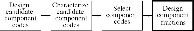
As shown in Figure 9.1, this chapter’s modifications of the EXIT-chart matching algorithm of [149] represent alterations to the method of selecting the component fractions that is employed during conventional irregular codec design.
Figure 9.1: Conventional irregular coding design process. This chapter presents modifications to the aspects of this process that are indicated using a bold box.
This chapter is organized as follows. In Section 9.2 we detail our modifications of the EXIT-chart matching algorithm of [149]. Our novel joint EXIT-chart matching algorithm is introduced in Section 9.3. The application of this algorithm is exemplified in the context of our novel IrVLC-IrURC scheme, which is introduced in Section 9.4. We detail the choice of parameters for our proposed transmission scheme in Section 9.5. Here, we additionally introduce benchmark parameterizations, where either one or both of the IrVLC-IrURC scheme’s irregular codecs is replaced by its regular equivalent. The achievable Bit-Error Ratio (BER) performance and computational complexity of our parameterizations are characterized and analyzed in Section 9.6. Finally, we offer our conclusions in Section 9.7.
9.2 Modifications of the EXIT-Chart Matching Algorithm
In this section we detail a number of modifications of the EXIT-chart matching algorithm of [149]. We assume a familiarity with Section VII and Table 1 of [149] and we adopt the notation of this reference for the remainder of this section. In the case of an outer IrVLC codec, the notation L is employed to represent the number N of component VLEC codebooks employed, while R IR represents the composite IrVLC coding rate RIrVLC. Furthermore, the notation α is employed to represent the fraction αn of the transmission frame that is encoded using the particular component VLEC codebook VLECn, while Ri is employed to represent the codebook’s coding rate R(VLECn), where i = n ∈ [1...N]. In the case of an inner IrURC codec, the number R of component URC codes is represented using the notation L, while the fraction αrof the transmission frame that is encoded using the particular component URC code URCr is represented by αi, where i = r ∈[1...R]. Note that, since all component URC codes have the same unity-valued coding rate, the composite IrURC coding rate will also be equal to unity: RIR = R1 = R2 = ··· = RL = 1. We therefore commence by detailing a modification to the EXIT-chart matching algorithm of [149] that eliminates the requirement for a target composite coding rate RIR to be specified and removes the constraint that would otherwise be analogous to Equation (9.4), as described in Section 9.1.
In the EXIT-chart matching algorithm of [149], adherence to the constraints of Equations (9.2) and (9.4) is achieved by maintaining the relationship
where

Here, the first and second rows of C and d maintain constraint (9.2) and constraint (9.4) respectively. Hence, constraint (9.4) may be removed by replacing C with a vector c = [1 1...1] in which all L number of elements are equal to unity and by replacing d with a unity-valued scalar d = 1 throughout Section VII and Table 1 of [149]. Note that these modifications require that the matrix T of Section VII and Table 1 of [149] becomes a L ×(L − 1) matrix, whose columns are a basis of the null space of c, of dimension L − 1.
The algorithm of [149] performs EXIT-chart matching by employing the steepest descent approach [309] to minimize a cost function J(α) = ||e||2, where e is a vector of distances between the irregular outer code’s inverted EXIT function and the serially concatenated inner code’s EXIT function. As described in Section 9.1, the algorithm of [149] may be adapted to jointly perform EXIT-chart matching and simultaneously seek a reduced computational complexity for the resultant irregular coding scheme’s APP SISO decoder. This may be achieved by specifying a vector o having a length L, comprising the average number of Add, Compare and Select (ACS) operations performed per LLR [292] during the APP SISO decoding of each component code using the Bahl–Cocke–Jelinek–Raviv (BCJR) algorithm [48] in the logarithmic probability domain and an eight-entry lookup table for correcting the Jacobian approximation [296]. With reference to Section VII of [149], the cost function may be adapted to consider the APP SISO decoder’s computational complexity according to
where y is a positive scalar value, which is commensurate with the relative importance of seeking a low computational complexity for the APP SISO decoder, or has a zero value if this complexity should not be considered during EXIT-chart matching.
During the steepest descent approach of [149], the gradient eb of the cost function J(α) is evaluated with respect to a vector β that is dependent on the vector α listing the constituent codes’ weights. This gradient eb is employed to iteratively update the vector β, and hence the weight vector α, in order to converge towards a minimal cost function J(α). The EXIT-chart matching algorithm may be adapted to additionally seek a reduced APP SISO decoding computational complexity by employing the cost function of Equation (9.7) during the derivation of eb and β. With reference to Section VII and Table 1 of [149], the revised eb and β are specified by
and
respectively.
Figure 9.2: Data-flow diagram of the joint EXIT-chart matching algorithm. ©IEEE [202] Maunder and Hanzo, 2009.

9.3 Joint EXIT-Chart Matching
In this section we detail a novel joint EXIT-chart matching algorithm. As described in Section 9.1, this allows the joint EXIT-chart matching of a pair of serially concatenated irregular codes that both support iterative decoding convergence to an infinitesimally low probability of error, in order to obtain the maximal effective throughput that maintains an open EXIT-chart tunnel. The data-flow diagram of the algorithm is provided in Figure 9.2. The algorithm of [149] is iteratively applied in order to match a pair of composite EXIT functions that are formed as superpositions of N outer component EXIT functions and R inner component EXIT functions respectively. However, at the commencement of the algorithm no composite EXIT functions are available. For this reason, the algorithm begins with the matching of the composite outer EXIT function to a single one of the R inner component EXIT functions, as shown in Figure 9.2. The specific choice of the inner component EXIT function that fulfills this role is therefore a parameter of the joint EXIT-chart matching algorithm. Following this, the algorithm alternates between the matching of the composite inner EXIT function to the composite outer EXIT function and vice versa.
The proposed joint EXIT-chart matching algorithm assumes that all inner component codes have the same coding rate, as is the case if they are all URCs, for example. The algorithm must therefore employ the appropriate modification to the EXIT-chart matching algorithm of [149] that was introduced in Section 9.2. Note that the designed irregular inner code will have an overall coding rate that equals those of the component codes in every iteration of the joint EXIT-chart matching algorithm.
By contrast, it is assumed that the outer component codes have a variety of coding rates. Hence, a target composite coding rate must be specified each time, when the algorithm of [149] is invoked for matching the composite outer EXIT function to the inner. For this reason, the joint EXIT-chart matching algorithm is parameterized by a series of incremental target outer coding rates. As the overall coding rate increases with each iteration, the open EXIT tunnel becomes narrower owing to the area property of EXIT charts [204]. However, the alternate matching of the composite inner and outer EXIT functions ensures that they will tend to converge to near-parallel shapes. In this way, an open EXIT tunnel may be maintained even for near-capacity operation.
Figure 9.3: Schematic of the IrVLC-IrURC scheme. ©IEEE [202] Maunder and Hanzo, 2009.

The iterative joint EXIT-matching algorithm continues, until the designed composite inner and outer EXIT functions intersect. At this point, the algorithm outputs the inner and outer component fractions found to yield the maximal coding rate, whilst maintaining an open EXIT tunnel.
9.4 Overview of the Transmission Scheme Considered
In this section we consider a transmission scheme that facilitates the joint source and channel coding of a sequence of source symbols having values with unequal probabilities of occurrence for near-capacity transmission over an uncorrelated narrowband Rayleigh fading channel. This application motivates the employment of an IrVLC, as discussed in Section 7.1. This outer codec is serially concatenated and iteratively decoded by exchanging extrinsic information with a novel IrURC used as the inner codec. Owing to its unity coding rate, the IrURC code avoids the effective throughput loss of the RTCM = 3/4-rate TCM codec employed in Chapter 7, as discussed in Section 8.1. Since this combined IrVLC-IrURC scheme employs two irregular codecs, it allows us to exemplify the joint EXIT-chart matching algorithm proposed in Section 9.3.
In the IrVLC-IrURC scheme, the outer IrVLC arrangement employs N component VLEC codebooks {VLECn}Nn=1 These codebooks have different coding rates of {R(VLECn)}Nn=1 and/or Real-Valued Free Distance Metrics (RV-FDMs) of {D(VLECn)}Nn=1, as described in Section 8.2. Furthermore, each component VLEC codebook is invoked for generating a particular fraction of the transmission frame, as described in Section 9.1. Similarly, the inner IrURC arrangement employs R component URC codes {URCr}Rr=1, having different generator and/or feedback polynomials [308]. The schematic of the IrVLC-IrURC scheme is provided in Figure 9.3, which is reminiscent of the schematic of Figure 8.6 using a regular inner code.
9.4.1 Joint Source and Channel Coding
We employ K = 16-ary source symbols having values obeying the probabilities of occurrence that result from the Lloyd–Max quantization [164, 165] of independent Gaussian distributed continuous-valued source samples, as exemplified in Section 7.2.1. These occurrence probabilities of {P(k)}Kk=1 = {0.008, 0.024, 0.043, 0.060, 0.076, 0.089, 0.097, 0.102, 0.102, 0.097, 0.089, 0.076, 0.060, 0.043, 0.024, 0.008} can be seen to vary by more than an order of magnitude. Since these probabilities correspond to varying numbers of {−log2(P(k)}Kk=1 = {6.93, 5.35, 4.55, 4.05, 3.72, 3.49, 3.36, 3.29, 3.29, 3.36, 3.49, 3.72, 4.05, 4.55, 5.35, 6.93} bits of information per symbol, the application of VLCs is motivated, since the source entropy is E = 3.77 bits of information per symbol, according to Equation (8.2).
In the transmitter shown in Figure 9.3, the source symbol frame s is decomposed into N sub-frames {sn}Nn=1, where each sub-frame sn = ![]() comprises a potentially different number Jn of K-ary source symbols
comprises a potentially different number Jn of K-ary source symbols ![]() ∈ [1...K]. Hence, the total number of source symbols in the source symbol frame s is given by
∈ [1...K]. Hence, the total number of source symbols in the source symbol frame s is given by

Each of the N source symbol sub-frames {sn}Nn=1 is VLEC-encoded using the corresponding VLEC codebook from the set {VLECn}Nn=1, where each VLEC codebook VLECn = {VLECn,k}Kk=1 comprises K VLEC codewords. During the VLEC encoding of the source symbol sub-frame sn = ![]() , each constituent source symbol
, each constituent source symbol ![]() having a particular value k ∈ [1...K] is represented by the corresponding VLEC codeword VLECn,k, having a length of In,k bits. Following this, the resultant set of Jn VLEC codewords {VLEC
having a particular value k ∈ [1...K] is represented by the corresponding VLEC codeword VLECn,k, having a length of In,k bits. Following this, the resultant set of Jn VLEC codewords {VLEC![]() }
}![]() is concatenated to obtain the transmission sub-frame un, which comprises a number of bits given by
is concatenated to obtain the transmission sub-frame un, which comprises a number of bits given by

Owing to the variable lengths of the VLEC codewords, the transmission sub-frame lengths {In}Nn=1 will typically vary from frame to frame. In order to facilitate the VLEC decoding of the transmission sub-frames {un}Nn=1, it is necessary to explicitly convey their lengths {In}Nn=1 to the receiver. Furthermore, this highly error-sensitive side information must be reliably protected against transmission errors, using a powerful low-rate block code, for example. For the sake of avoiding obfuscation, this is not shown in Figure 9.3. In Section 8.5.5 we comment on the amount of side information that is required for reliably conveying the specific number of bits in each transmission sub-frame to the decoder. As described in Section 8.5.5, we may expect the required amount of side information to be negligible compared with the transmission frame length Isum, since, as in the IrVLC-URC scheme of Section 8.4, we employ only a single transmission sub-frame per component VLEC codebook.
In the scheme’s transmitter, the N transmission sub-frames {un}Nn=1 are concatenated. As shown in Figure 9.3, the resultant transmission frame u comprises a number of bits given by
where Isum will typically vary from frame to frame. Note that the average fractions αn = In/Isum of the transmission frame u that are generated by each VLEC component code VLECn may be chosen in order to shape the inverted EXIT function of the IrVLC code, as detailed in Section 9.5. The corresponding fractions Cn = J/Jsum of the source symbol frame s that should be encoded by each VLEC component code VLECn may be obtained as
where RIrVLC is the composite IrVLC coding rate.
In the transmitter shown in Figure 9.3, the transmission frame u is interleaved using a random Isum-bit interleaver π1 in order to obtain the interleaved transmission frame u′. This is decomposed into R sub-frames {u′r}Rr=1, where each sub-frame u′r = ![]() comprises Irbits. Each of the R interleaved transmission sub-frames {u′r}Rr=1 is URC-encoded using the corresponding URC from the set {URCr}Rr=1. Note that the fraction αr = Ir/Isum of the interleaved transmission frame u′ that is encoded by each component URC code URCr may be chosen in order to shape the EXIT function of the IrURC codec, as detailed in Section 9.5. Since all URCs have a coding rate of unity, the resultant IrURC-encoded sub-frames {vr}Rr=1 have the same lengths as the corresponding interleaved transmission sub-frames {u′r}Rr=1. As shown in Figure 9.3, the IrURC-encoded sub-frames {vr}Rr=1 are concatenated to provide the IrURC-encoded frame v, having a length of Isum bits.
comprises Irbits. Each of the R interleaved transmission sub-frames {u′r}Rr=1 is URC-encoded using the corresponding URC from the set {URCr}Rr=1. Note that the fraction αr = Ir/Isum of the interleaved transmission frame u′ that is encoded by each component URC code URCr may be chosen in order to shape the EXIT function of the IrURC codec, as detailed in Section 9.5. Since all URCs have a coding rate of unity, the resultant IrURC-encoded sub-frames {vr}Rr=1 have the same lengths as the corresponding interleaved transmission sub-frames {u′r}Rr=1. As shown in Figure 9.3, the IrURC-encoded sub-frames {vr}Rr=1 are concatenated to provide the IrURC-encoded frame v, having a length of Isum bits.
As shown in Figure 9.3, the IrURC-encoded frame v is interleaved using a random Isum-bit interleaver π 2 and modulated using Gray-coded [310] MQAM = 16QAM [300], as shown in the constellation diagram of Figure 9.4. As described in Section 9.1, we employ 16QAM in order to benefit from the throughput of log2(MQAM) = 4bits per symbol, which is higher than the BPSK throughput of 1 bit per symbol employed in the IrVLC-URC scheme of Section 8.4. Note that Gray-coded 16QAM is employed since it minimizes the cost of omitting the iterative exchange of extrinsic information between the demodulator and the APP SISO URC decoder [311], as detailed in Section 9.5.2. This facilitates an implementational and computational complexity saving in the receiver of Figure 9.3, which does not perform iterative demodulation and APP SISO IrURC decoding. Following modulation, the resultant channel input symbols x are transmitted over an uncorrelated narrowband Rayleigh fading channel and are received as the channel output symbols y, as seen in Figure 9.3.
9.4.2 Iterative Decoding
Although no extrinsic information is iteratively exchanged between the demodulator and the APP SISO IrURC decoder of Figure 9.3, the APP SISO IrURC and IrVLC decoding operations are performed iteratively. Both of these decoders invoke the BCJR algorithm [48] applied to bit-based trellises [141, 180]. All BCJR calculations are performed in the logarithmic probability domain and using an eight-entry lookup table for correcting the Jacobian approximation [296]. Note that this approach requires only the use of ACS operations. Extrinsic soft information, represented in the form of LLRs [292], is iteratively exchanged between the IrURC and IrVLC decoding stages of Figure 9.3 for the sake of assisting each other’s operation. In Figure 9.3, L(•) denotes the LLRs of the bits concerned, where the superscript m denotes demodulation, i indicates inner IrURC decoding and o corresponds to outer IrVLC decoding. Additionally, the specific subscript denotes the dedicated role of the LLRs, with a, p and e indicating a priori, a posteriori and extrinsic information, respectively. Similarly, a tilde over the notation represents a reconstructed estimate of the bits or symbols concerned.
Figure 9.4: Constellation diagram for the MQAM = 16-level Gray-coded QAM modulation scheme. For an average transmit energy of unity, a =1/![]() .
.

Following the demodulation of the channel output symbols y of Figure 9.3, the resultant LLR frame Lme(v) is deinterleaved π2−1 and provided to the APP SISO IrURC decoder as the a priori LLR frame Lia(v). Just as R separate URC encoding processes are employed in the IrVLC-IrURC scheme’s transmitter, R separate APP SISO URC decoding processes are employed in its receiver. In parallel with the composition of the IrURC-encoded frame v from R sub-frames, the corresponding a priori LLR frame Lia(v) is decomposed into R number of sub-frames following deinterleaving π2−1, as shown in Figure 9.3. Similarly, the LLR frame Lia(u′) representing the interleaved transmission frame is decomposed into R sub-frames. Each of the R APP SISO URC decoding processes is provided with the corresponding a priori LLR sub-frames Lia(vr) and Lia(u′r) and in response it generates the a posteriori LLR sub-frame Lip(u′r). These a posteriori LLR sub-frames are concatenated in order to provide the a posteriori LLR frame Lip(u′), as shown in Figure 9.3.
Similarly, N separate APP SISO VLEC decoding processes are employed in the IrVLC-IrURC receiver. In parallel with the composition of the transmission frame u from N sub-frames, the corresponding a priori LLR frame Loa(u) is decomposed into N sub-frames, as shown in Figure 9.3. This is achieved with the aid of the explicit side information that conveys the number of bits In in each transmission sub-frame un. Each of the N VLEC decoding processes is provided with the a priori LLR sub-frame Loa(un) and in response it generates the a posteriori LLR sub-frame Lop(un). These a posteriori LLR sub-frames are concatenated in order to provide the a posteriori LLR frame Lop(u), as shown in Figure 9.3.
Table 9.1: Considered parameterizations of the IrVLC-IrURC scheme

During the final decoding iteration, N bit-based Maximum A posteriori Probability (MAP) VLEC sequence estimation processes are invoked instead of APP SISO VLEC decoding, as shown in Figure 9.3. In this case, each transmission sub-frame un is estimated from the corresponding a priori LLR sub-frame Loa(un). The resultant transmission sub-frame estimates ![]() n are VLEC decoded to provide the source symbol sub-frame estimates s˜n. Note that the bit-based MAP sequence estimator is unable to exploit the knowledge that the particular source symbol sub-frame sn should comprise Jn source symbols. In order that we may prevent the loss of synchronization that would result if the source symbol sub-frame estimate s˜n did not comprise Jn source symbol estimates, an appropriate number of dummy symbols are removed from, or appended to, the end of s˜n accordingly. Finally, the set of adjusted source symbol sub-frame estimates
n are VLEC decoded to provide the source symbol sub-frame estimates s˜n. Note that the bit-based MAP sequence estimator is unable to exploit the knowledge that the particular source symbol sub-frame sn should comprise Jn source symbols. In order that we may prevent the loss of synchronization that would result if the source symbol sub-frame estimate s˜n did not comprise Jn source symbol estimates, an appropriate number of dummy symbols are removed from, or appended to, the end of s˜n accordingly. Finally, the set of adjusted source symbol sub-frame estimates ![]() may be concatenated to provide the source symbol frame estimate s˜, as shown in Figure 9.3.
may be concatenated to provide the source symbol frame estimate s˜, as shown in Figure 9.3.
9.5 System Parameter Design
Throughout this section we introduce a number of different parameterizations of the IrVLC-IrURC scheme of Section 9.4. We refer to these as the IrVLC-IrURC-high, the IrVLC-IrURC-low and the IrVLC-URC-high parameterizations. In Section 9.5.4 we additionally introduce a fourth parameterization, which we refer to as the VLC-URC arrangement. Our four parameterizations are summarized in Table 9.1.
9.5.1 Component VLEC codebooks
As described in Section 9.4, the IrVLC-IrURC scheme employs N component VLEC codebooks and R component URC codes. However, observe in Table 9.1 that the values of N and R vary amongst our parameterizations considered. In the IrVLC-IrURC-high, IrVLC-IrURC-low and IrVLC-URC-high parameterizations, the IrVLC arrangement employs N = 30 component VLEC codebooks {VLECn}30n=1 for generating particular fractions {αn}30n=1 of the transmission frame u, as described in Section 9.4. These N = 30 component VLEC codebooks {VLECn}30n=1 were designed using the Genetic Algorithm (GA) of Section 8.3 to have a range of coding rates {R(VLECn)}30n=1 and RV-FDMs {D(VLECn)}30n=1. More specifically, maximal RV-FDMs were sought for coding rates in the range of [0.25, 0.95] during the generation of the first 15 of the N = 30 component VLEC codebooks {VLECn}15n=1 as described in Section 8.5.1. By contrast, RV-FDMs that are as close as possible to, but no less than, two were sought during the generation of the remaining 15 component VLEC codebooks {VLECn}30n=1, which also have coding rates in the range of [0.25, 0.95]. Note that since all N = 30 component VLEC codebooks employ a RV-FDM of at least two, the corresponding inverted EXIT functions will reach the top right-hand corner of the EXIT chart [298], as detailed below. The coding rate R(RVLCn), RV-FDM D(RVLCn) and the composition of the N = 30 component VLEC codebooks {VLECn}30n=1 are provided in Tables 9.2 and 9.3.
The inverted EXIT functions of the N = 30 component VLEC codebooks in the suite {VLECn}30n=1 are provided in Figure 9.5. These were obtained by simulating the VLEC encoding and APP SISO decoding of 100 frames of 10 000 randomly generated source symbols. As described in Section 9.4, these source symbols have K = 16-ary values with the probabilities of occurrence that result from the Lloyd–Max quantization [164, 165] of independent Gaussian distributed source samples. The corresponding frames of VLEC-encoded bits were employed to generate uncorrelated Gaussian distributed a priori LLR frames having a range of mutual informations Iao∈ [0, E(VLECn)], where E(VLECn) is the VLEC-encoded bit entropy of the considered component VLEC codebook VLECn. Note that the VLEC-encoded bit entropy E(VLECn) was found to be only at a negligible distance from unity in the case of all considered component VLEC codebooks {VLECn}30n=1. Finally, all mutual information measurements were carried out using the histogram-based approximation of the LLR PDFs [294]. For each considered component VLEC codebook VLECn, the coding rate R(VLECn) and RV-FDM D(VLECn) are provided in Figure 9.5. Furthermore, the computational complexity of APP SISO decoding is characterized by the average number OAPP(VLECn) of ACS operations performed per source symbol.
Observe in Figure 9.5 that the inverted EXIT functions of all N = 30 component VLEC codebooks {VLECn}30n=1 reach the top right-hand corner of the EXIT chart, as described above. Note that ‘S’-shaped inverted EXIT functions having up to two points of inflection are obtained in Figure 9.5 for the component VLEC codebooks {VLECn}15n=1, which have high RV-FDMs, as explained in Section 8.2. By contrast, the low RV-FDM VLEC codebooks {VLECn}30n=1 are associated with EXIT functions having no more than a single point of inflection. Since the suite of N = 30 VLEC codebooks {VLECn}30n=1 is associated with a wide variety of inverted EXIT functions, it is particularly suitable for use in IrVLCs, as concluded in Chapter 8. Also note that the high RV-FDM VLEC codebooks {VLECn}15n=1 are associated with higher APP SISO decoder complexities than are the low RV-FDM VLEC codebooks {VLECn}30n=1, as was also observed in Section 8.5.1.
9.5.2 Component URC Codes
In the same way that the IrVLC-IrURC scheme employs N component VLEC codebooks, it also employs R component URC codes, as described in Section 9.4. However, the value of R varies amongst our considered parameterizations, as described above. More specifically, the IrVLC-IrURC-high and the IrVLC-IrURC-low parameterizations of Table 9.1 employ R = 10 component URC codes {URCr}10r=1. By contrast, the benchmark IrVLC-URC-high parameterization of Table 9.1 employs only the component URC code URC1 having the lowest coding memory of LURC = 1, and hence imposes the lowest APP SISO decoding complexity [141]. Since the IrVLC-URC-high parameterization employs just R = 1 component URC code, it can be thought of as employing a regular URC instead of an IrURC.
Table 9.2: Properties and composition of the 15 component VLEC codebooks {VLECn}15n=1 that were designed to have high RV-FDMs
| VLECn | Properties† | Composition‡ |
| VLEC1 | (0.950, 2.412) | 6,6,5,5,3,4,3,3,3,4,4,4,5,5,6,6, 317E29FEA2490F1EA1 |
| VLEC2 | (0.900, 2.518) | 6,6,5,4,3,5,3,4,4,3,5,4,5,5,6,6, 3A5F8580E52ABCF1321 |
| VLEC3 | (0.850, 2.617) | 6,7,5,5,4,4,3,3,5,4,4,5,5,6,7,8, 140DE2BCB304A54F6D818 |
| VLEC4 | 0.800, 2.710) | 6,7,6,6,5,3,4,3,4,4,5,5,6,7,7,8, 23B98BDB09CA5D5B60BE3C |
| VLEC5 | (0.750, 2.793) | 7,8,7,6,6,4,5,4,5,4,5,3,6,5,8,7, 1761E3F330FB2A494F8AD1C |
| VLEC6 | (0.701, 2.922) | 7,7,7,6,6,6,5,4,4,5,6,6,5,5,6,7, E45F40FBC3DB413C43A3C12 |
| VLEC7 | (0.650, 2.981) | 7,7,8,7,7,5,6,4,6,4,6,5,6,7,8,7, 3540C30FF578C04E753C1862D |
| VLEC8 | (0.601, 4.364) | 13,10,9,8,7,6,5,4,4,5,6,7,8,8,9,10, 49AA7CA652B36B3E065564E5554E43 |
| VLEC9 | (0.550, 4.628) | 11,11,10,8,7,5,5,4,7,6,6,7,9,11,9,12, 1E73F274A5646CFC1295595C0C1211F4 |
| VLEC10 | (0.501, 4.807) | 13,11,9,11,7,8,6,5,5,6,8,7,9,11,12,13, 13192CCD6E0F556B3F80CA55438997333A69 |
| VLEC11 | (0.450, 5.869) | 14,10,10,9,9,8,8,6,7,7,8,9,11,10,11,12, 1FAEDF0F996FDB34623C056DCB66384ED78FF4 |
| VLEC12 | (0.400, 6.573) | 15,15,11,10,13,10,7,6,6,9,8,9,12,14,13,18, 3AD43A94E6964B2A9B38FE0471599674D2B5581C7587 |
| VLEC13 | (0.350, 8.475) | 15,14,16,14,12,10,9,8,8,9,10,11,13,13,15,16, 1522D8CA63D49CD714DB2F0FF8007A4D358B39A6353669C2B |
| VLEC14 | (0.301, 10.384) | 17,16,15,14,13,12,11,10,9,11,12,13,14,15,28,17, 367E727298F26E57CE7A6D5E41F002C6BCB4D72ED5AD7393AAAE3ABA7 |
| VLEC15 | (0.251, 12.449) | 25,18,17,16,15,14,13,12,11,13,14,15,28,17,18,19, 1670497B3BC1D9DAEB73994EB37CF183F00038E2D9276B2CE0FB5B6736BDA6AE3E8 |
† The properties of each component VLEC codebook VLECn are provided using the format (R(VLECn), D(VLECn)).
‡ The composition of each component VLEC codebook VLECn is specified by providing the K = 16 codeword lengths {In,k}Kk=1, together with the hexadecimal representation of the ordered concatenation of the K = 16 VLEC codewords {VLECn,k}Kk=1 in the codebook.
Note that since the IrVLC-IrURC-high and the IrVLC-IrURC-low parameterizations employ two irregular codecs, they can benefit from the joint matching of their EXIT functions, as described in Section 9.3. By contrast, the only irregular codec employed by the IrVLC-URC-high benchmark parameterization of Table 9.1 is an IrVLC, permitting only the matching of its inverted EXIT function to the fixed EXIT function of the URC codec, as demonstrated for the similar IrVLC-URC scheme of Section 8.5.3.
Table 9.3: Properties and composition of the 15 component VLEC codebooks {VLECn}30n=1 that were designed to have low RV-FDMs
| VLECn | Properties† | Composition‡ |
| VLEC16 | (0.952, 2.394) | 8,6,5,5,4,4,3,3,3,3,4,4,5,5,6,6, 0DD7E2A52878BCF1321 |
| VLEC17 | (0.901, 2.373) | 6,7,5,6,4,4,3,3,3,3,4,5,6,4,8,7, 0C59CEBD331494BCAD1A |
| VLEC18 | (0.851, 2.357) | 9,4,5,8,5,4,3,3,3,3,5,4,6,6,7,10, 0B7FE2D1D2B1944BF4B16C |
| VLEC19 | (0.800, 2.312) | 7,8,8,5,5,6,3,3,3,3,5,5,6,6,8,7, E869D9CF9998A4394A1617 |
| VLEC20 | (0.750, 2.308) | 7,8,5,7,6,6,3,3,3,3,6,6,9,6,4,7, 0A96B8B17533152456FD7A7 |
| VLEC21 | (0.700, 2.275) | 16,11,7,9,5,5,3,3,3,3,5,7,5,9,13,15, 1555154E857FF350C850E542AA1554 |
| VLEC22 | (0.653, 2.269) | 14,11,11,7,9,5,3,3,3,3,5,7,5,9,16,12, 1558553AA17EA7350C850E542AB42AA |
| VLEC23 | (0.605, 2.257) | 12,14,10,11,6,6,3,3,3,3,6,7,15,6,8,10, 1DD1DDE761DCF0C74628E1DDC3CE8EF |
| VLEC24 | (0.553, 2.225) | 10,14,8,12,5,6,3,3,3,3,9,15,5,13,11,16, 368DB73736C21998A6C36D8736D1B736DA |
| VLEC25 | (0.501, 2.133) | 11,17,8,8,9,5,6,2,2,3,12,18,5,15,11,14, 0DA1B6DCD0DCD843181B61B6D8736D86DCDB7 |
| VLEC26 | (0.451, 2.133) | 11,14,6,15,9,5,2,5,3,2,12,21,8,18,14,17, 0DB9B6861B6C3612384DB0DB6D86E6DB61B6E6DB7 |
| VLEC27 | (0.407, 2.113) | 8,17,9,12,21,5,6,2,3,2,12,24,5,15,14,18, 06E6DB7361B79B6DB0862236C36DB6C39B6C36DCDB6C |
| VLEC28 | (0.350, 2.155) | 13,19,7,17,10,10,7,3,3,3,13,37,6,16,16,24, 36D1B6D9346DB7368D932C536C9B6D804764936D936DA36DB01 |
| VLEC29 | (0.300, 2.123) | 8,19,8,12,9,6,5,2,2,3,42,45,5,15,11,17, 06E6DB50D0DB0D861181B6D593DC586DB564F716C39B6C36E6DB4 |
| VLEC30 | (0.252, 2.117) | 8,14,8,9,12,6,5,2,3,2,56,62,5,15,11,11, 06E6DB9A1B0DB0C22236DB34343BEB6C36DB34343BEB6DB0E6DB0DB9B4 |
† The properties of each component VLEC codebook VLECn are provided using the format (R(VLECn), D(VLECn)).
‡ The composition of each component VLEC codebook VLECn is specified by providing the K = 16 codeword lengths {In,k}Kk=1, together with the hexadecimal representation of the ordered concatenation of the K = 16 VLEC codewords {VLECn,k}Kk=1 in the codebook.
Figure 9.5: Inverted EXIT functions for the N = 30 component VLEC codebooks {VLECn}30n=1. Curves are labeled using the format VLECn(R(VLECn), D(VLECn), OAPP(VLECn)). © IEEE [202] Maunder and Hanzo, 2009.

The Linear Feedback Shift Register (LFSR) designs of Figure 9.6 were selected for the R = 10 component URC codes {URCr}10r=1 from the set of all possible designs containing a number of memory elements in the set LURC ∈ {1, 2, 3}. The selected codes were chosen in order to yield the sufficiently diverse variety of EXIT function shapes that are provided in Figure 9.7, together with the corresponding generator and feedback polynomials. These EXIT functions were obtained by simulating the URC encoding and APP SISO decoding of 100 frames of 10 000 randomly generated bits in the context of transmission over a MQAM = 16QAM-modulated uncorrelated narrowband Rayleigh fading channel having a SNR of Ec/N0 = 8 dB. The randomly generated bits were employed to generate uncorrelated Gaussian distributed a priori LLR frames having a range of mutual informations Ia ∈ [0, 1] and all mutual information measurements were carried out using the histogram-based approximation of the LLR PDFs [294].
Figure 9.6: LFSR encoder schematics for the component URC codes {URCr}10r=1.
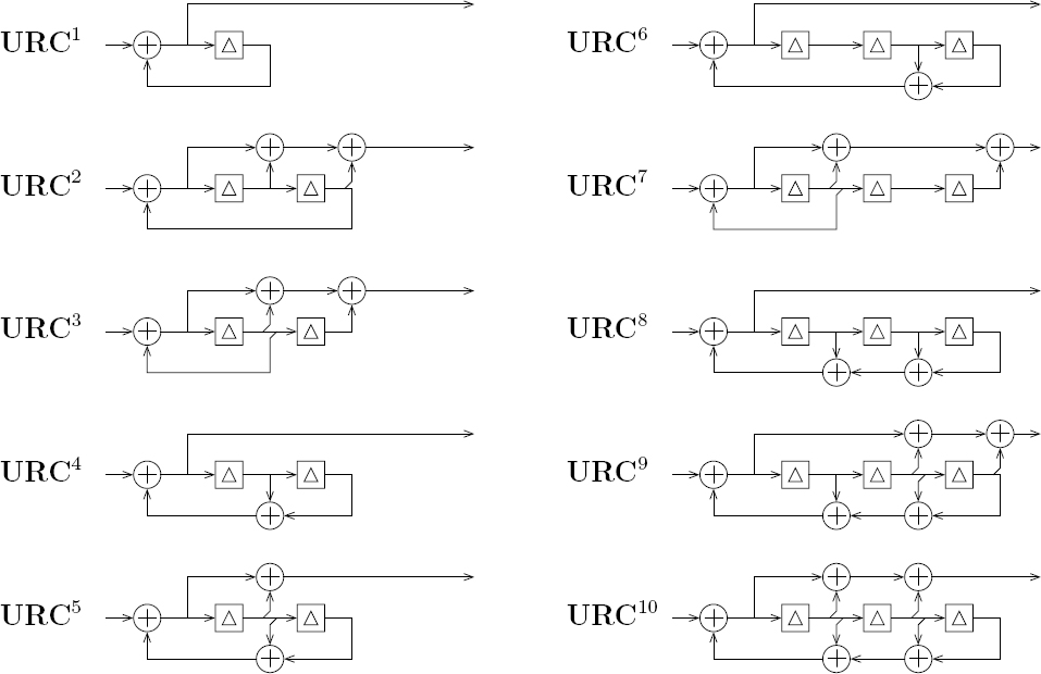
Note that some URC component EXIT functions of Figure 9.7 emerge from the (0, 0) point of the EXIT chart. By contrast, the component URCs URC1, URC4, URC6 and URC8 offer some nonzero extrinsic mutual information Iei even in the absence of any a priori mutual information Iai. This may be attributed to the presence of only a single nonzero coefficient within their generator polynomials [312], as shown in Figures 9.6 and 9.7. Furthermore, since each of the R = 10 component URC codes {URCr}10r=1 employs recursive feedback in Figure 9.6, the EXIT functions of Figure 9.7 reach the top right-hand corner of the EXIT chart, as described in [299]. Since the inverted EXIT functions of our component VLEC codebooks also reach the top right-hand corner of the EXIT chart, we can expect to achieve open EXIT-chart tunnels [267] if the channel quality is sufficiently high. As discussed in Section 4.3, this implies that iterative decoding convergence to an infinitesimally low probability of error is facilitated, provided that the iterative decoding trajectory approaches the inner and outer EXIT functions sufficiently closely.
Figure 9.7: EXIT functions for the R = 10 component URC codes {URCr}10r=1 for a 16QAM-modulated Rayleigh fading channel SNR of Ec/N0 = 8 dB. Curves are labeled using the format URC (g(URC), f(URC)), where g(URC) and f(URC) are the hexadecimal generator and feedback polynomials of the URC code, respectively [296]. ©IEEE [202] Maunder and Hanzo, 2009.

Note that the EXIT chart area property [204] suggests that, when multiplied by log2(MQAM) = 4, the area beneath the component URC EXIT functions should equal the channel’s capacity, since the component URC codes have unity-valued coding rates. However, the average area beneath the component URC EXIT functions of Figure 9.7 was found to equal 0.538. Upon multiplying this value by log2(MQAM) = 4, the resultant value of 2.154 is found to be slightly lower than the 16QAM-modulated Rayleigh fading channel’s capacity at the corresponding SNR of Ec/N0 = 8 dB, which is 2.209 bits per channel symbol [300]. This discrepancy may be explained by the lack of an iterative exchange of extrinsic information between the demodulator and the URC-based inner APP SISO decoder, as shown in Figure 9.3. To illustrate this point, the EXIT function corresponding to the Gray-coded MQAM = 16QAM demodulator is provided in Figure 9.8 for a Rayleigh fading channel SNR of Ec/N0 = 8 dB. Since iterative demodulation is not employed, the LLR frame Lme(v) of Figure 9.3 will only have the mutual information Iem associated with a zero-valued a priori mutual information Ima and will be unable to reach that associated with a higher value of Ima In the Ec/N0 = 8 dB scenario shown in Figure 9.8, the LLR frame Lme(v) will have a mutual information of Ime = 0.544 and will be unable to reach the maximal value of 0.560. Note that, upon multiplying the area beneath the demodulator’s EXIT function by log2(MQAM) = 4, the channel capacity of 2.209 bits per symbol is obtained. Also note that these findings are contrary to those of Section 8.5.4, where the area beneath the URC EXIT functions was found to be equal to the corresponding channel capacities. However, in this case BPSK modulation was employed, for which there is no benefit in performing iterative demodulation [300].
Figure 9.8: EXIT functions for the Gray-coded demodulator for a Rayleigh fading channel SNR of Ec/N0 = 8 dB. ©IEEE [202] Maunder and Hanzo, 2009.

9.5.3 EXIT-Chart Matching
The IrVLC arrangement of the benchmark IrVLC-URC-high parameterization of Table 9.1 was designed using the EXIT-chart matching algorithm of [149]. By contrast, the joint EXIT-chart matching algorithm of Section 9.3 was employed for the design of the IrVLC and IrURC arrangements of the IrVLC-IrURC-high and the IrVLC-IrURC-low parameterizations. In the case of the IrVLC-IrURC-low parameterization, the method of Section 9.2 was used for jointly performing EXIT-chart matching and for reducing the corresponding APP SISO decoder’s computational complexity. The low complexity that we sought for this arrangement explains why we refer to it as the IrVLC-IrURC-low parameterization. Recall that Section 8.6 observed that the computational complexity of IrVLCs typically dominates that of iterative decoding. For this reason we opted for employing the method of Section 9.2 to reduce the computational complexity associated with only the IrVLC and not the IrURC scheme. Hence, a weighting coefficient of y = 10−5 was employed when designing the IrVLC scheme, while a value of y = 0 was used for designing the IrURC scheme, as shown in Table 9.1. Note that the method of Section 9.2 invoked for jointly performing EXIT-chart matching and for reducing the corresponding APP SISO decoding complexity was not employed in the design of the therefore relatively high-complexity IrVLC-IrURC-high parameterization, as shown in Table 9.1. The comparison of the IrVLC-IrURC-high and IrVLC-IrURC-low parameterizations will therefore facilitate the characterization of the complexity reduction method of Section 9.2. Note that this modification of the EXIT-chart matching algorithm of [149] was found to offer no significant APP SISO decoder complexity reduction when regular URCs were employed. It is for this reason that we do not consider an ‘IrVLC-URClow’ parameterization.
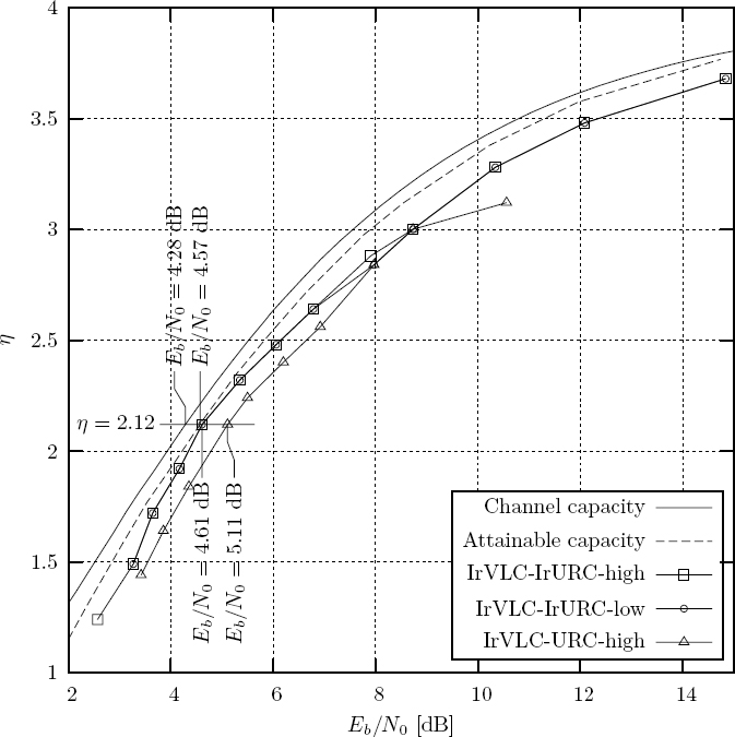
For the IrVLC-IrURC-high, IrVLC-IrURC-low and IrVLC-URC-high parameterizations, EXIT-chart matching was performed for a number of 16QAM Rayleigh fading channel SNRs in the range of Ec/N0 ∈ [3.5, 20.5] dB. In each case we sought the highest IrVLC coding rate RIrVLC for which an open EXIT-chart tunnel could be achieved. Since the IrURC and URC arrangements have unity coding rates, and because MQAM = 16QAM is employed in all parameterizations, the effective throughput of each parameterization is given by η = RIrVLC • log2(MQAM) bits per channel use, where RIrVLC is the IrVLC coding rate. Additionally, note that the channel SNR values of Ec/N0 may be converted to Eb/N0 values according to Eb/N0 = Ec/N0 • 1/η, where N0 is the noise power spectral density, and Ec and Eb are the transmit energy per channel use and per bit of source information respectively. The maximum effective throughput η for which open EXIT-chart tunnels were created for a range of 16QAM Rayleigh fading channel Eb/N0 values are plotted in Figure 9.9 for the IrVLC-IrURC-high, the IrVLC-IrURC-low and the IrVLC-URC-high parameterizations.
Note that Figure 9.9 also provides plots of the channel’s capacity [300] and the channel’s attainable capacity versus Eb/N0, as described above. Here, the channel’s attainable capacity is obtained for each particular Eb/N0 value by multiplying the average area beneath the corresponding EXIT functions of the R = 10 component URC codes by log2(MQAM) = 4, as described above. Note that the channel’s attainable capacity represents an upper bound to the maximum effective throughput η for which an open EXIT-chart tunnel can be achieved. This is because a parameterization’s effective throughput may be approximated by multiplying the area beneath the inverted IrVLC EXIT function by log2(MQAM) = 4 [204]. Since this area must be lower than that beneath the inner EXIT function in order for an open EXIT chart to be facilitated, iterative decoding convergence to an infinitesimally low probability of error is prevented when the effective throughput η is higher than the channel’s attainable capacity. The discrepancy between the channel’s capacity and its attainable capacity therefore imposes an effective throughput loss. Note that we propose a method for mitigating this effective throughput loss during our discussion of future work in Section 12.12.
In Figure 9.9, the IrVLC-IrURC-high and IrVLC-IrURC-low parameterizations can be seen to consistently maintain open EXIT-chart tunnels at higher effective throughputs than the IrVLC-URC-high parameterization does, across the entire range of Eb/N0 values considered. This may be explained by the higher degree of design freedom that is facilitated by the joint EXIT-chart matching algorithm that was employed to design the IrVLC-IrURC-high and IrVLC-IrURC-low parameterizations of Table 9.1. Whilst both the IrVLC-IrURC-high and the IrVLC-IrURC-low parameterizations are capable of creating open EXIT-chart tunnels for Eb/N0 values above a threshold that is within 0.8 dB of the channel’s Eb/N0 capacity bound for effective throughputs in the range [1.24,2.68], the IrVLC-URC-high parameterization of Table 9.1 can only achieve this above a less desirable threshold that is within about 1.2 dB of the channel’s Eb/N0 capacity bound. Furthermore, the IrVLC-IrURC-high and IrVLC-IrURC-low parameterizations of Table 9.1 can achieve this latter feat for more desirable effective throughputs of up to 3.06 bits per channel use.
Figure 9.9: The maximum effective throughput for which open EXIT-chart tunnels could be achieved versus 16QAM-modulated Rayleigh fading channel Eb/N0 for the IrVLC-IrURC-high, IrVLC-IrURC-lowand IrVLC-URC-high parameterizations of Table 9.1. The channel’s capacity and attainable capacity plots are additionally provided [300]. ©IEEE [202] Maunder and Hanzo, 2009.
9.5.4 Parameterizations of the Proposed Scheme
For the remainder of this chapter, we consider only the IrVLC-IrURC-high, IrVLC-IrURClow and IrVLC-URC-high arrangements obtained in Section 9.5.3 that have an effective throughput of η = 2.12 bits per channel use. This effective throughput corresponds to an IrVLC coding rate of RIrVLC = 0.53, to an Eb/N0 capacity bound of 4.28 dB [300] and an attainable Eb/N0 capacity bound of 4.57 dB, as shown in Figure 9.9.
As described in Section 9.5.3, the EXIT-chart matching algorithms of [149] and Section 9.3 were employed to shape the inverted IrVLC EXIT functions of our arrangements by appropriately selecting the fraction Cn of the source symbol frame s and the fraction αn of the transmission frame u that is encoded by each component VLEC codebook VLECn. These fractions are summarized for the IrVLC-IrURC-high, IrVLC-IrURC-low and IrVLC-URC-high arrangements in Table 9.4.
Let us now discuss the properties of each arrangement’s activated component VLEC codebooks. These are employed to encode a nonzero fraction Cn of the source symbol frame s and hence, a nonzero fraction αn of the transmission frame u. Observe in Table 9.4 that while the IrVLC-URC-high arrangement activates only component VLEC codebooks from the set {VLECn}15n=1 designed by the GA of Section 8.3 to have high RV-FDMs, the IrVLC-IrURC-high and IrVLC-IrURC-low arrangements additionally activate the low RV-FDM components {VLECn}30n=1. Note that this is particularly true in the case of the IrVLC-IrURC-low arrangement, which encodes nearly 99% of the source symbols using component VLEC codebooks from the set {VLECn}30n=16 designed by the GA of Section 8.3 to have low RV-FDMs. In the case of the IrVLC-IrURC-high arrangement, the corresponding percentage is just over 38%.
Furthermore, the EXIT-chart matching algorithm of Section 9.3 was employed to shape the inverted IrURC EXIT functions of our IrVLC-IrURC-high and IrVLC-IrURC-low arrangements by appropriately selecting the fraction αn of the interleaved transmission frame u′ that is encoded by each component URC code URCr. These fractions are summarized in Table 9.5.
Observe in Table 9.5 that in the IrVLC-IrURC-high arrangement nearly 93% of the IrURC-encoded bits are generated by the component URC codes {URCr}5r=1 employing LURC = 2 memory elements in their LFSRs, as shown in Figure 9.6. The remaining 7% of the IrURC-encoded bits are generated by the component URC codes {URCr}10r=1 employing LURC = 3 memory elements in their LFSRs. In contrast, in the IrVLC-IrURC-low arrangement, 78% and 22% of the IrURC-encoded bits are generated by the component URC codes employing LURC = 2 and LURC = 3 memory elements in their LFSRs, respectively. Since the APP SISO URC decoding complexity is proportional to 2LURC [141], a lower APP SISO IrURC decoding complexity can be expected for the IrVLC-IrURC-high arrangement than the IrVLC-IrURC-low arrangement. Furthermore, the lowest inner APP SISO decoding complexity can be expected for the IrVLC-URC-high arrangement, in which all IrURCencoded bits are generated by the component URC code URC1 employing just LURC = 1 memory element, as described in Section 9.5.2.
In this section we additionally introduce the VLC-URC benchmark of Table 9.1, which employs only N = 1 component VLEC codebook and R =1 component URC codebook. This benchmark therefore represents the serial concatenation and iterative decoding of regular VLC and URC codecs. Like the IrVLC-URC-high parameterization, our so-called VLCURC arrangement employs only the component URC code URC1 from Figure 9.6, which has the lowest coding memory of LURC = 1 and, hence, the lowest APP SISO decoding complexity [141]. The VLC-URC arrangement employs a VLEC codebook VLEC31 that was specially designed using the GA of Section 8.3 to have a coding rate R(VLEC31) = 0.53 equal to those of the above-mentioned IrVLC-IrURC-high, IrVLC-IrURC-low and IrVLC-URC-high arrangements. Furthermore, this codebook was designed to have a high RVFDM of D(VLEC31) = 4.665 since the corresponding ‘S’ -shaped inverted EXIT function was found to offer a relatively good match with the EXIT function associated with the component URC code URC1, as will be shown in Figure 9.10. The composition of the VLEC codebook VLEC31 is provided in Table 9.6.
Table 9.4: Properties of the 30 component VLEC codebooks {VLECn}30n=1, together with the fractions {Cn}30n=1 of the source symbol frame s and the fractions {αn}30n=1 of the transmission frame u that they encode in the η = 2.12 bits per channel symbol IrVLC-IrURC-high, IrVLC-IrURC-low and IrVLC-URC-high arrangements

† The properties of each component VLEC codebook VLECn are provided using the format (R(VLECn), D(VLECn)).
‡ The fractions are specified using the format (Cn, αn).
Table 9.5: Fractions {αr}10r=1 of the interleaved transmission frame u′ and the IrURC encoded frame v that the 10 component URC codes {URCr}10r=1 encode in the η = 2.12 bits per channel symbol IrVLC-IrURC-high and IrVLC-IrURC-low arrangements
| αr | ||
| URCr | IrVLC-IrURC-high | IrVLC-IrURC-low |
| URC1 | 0.000 | 0.000 |
| URC2 | 0.043 | 0.164 |
| URC3 | 0.258 | 0.000 |
| URC4 | 0.000 | 0.000 |
| URC5 | 0.627 | 0.619 |
| URC6 | 0.039 | 0.121 |
| URC7 | 0.000 | 0.000 |
| URC8 | 0.000 | 0.000 |
| URC9 | 0.013 | 0.000 |
| URC10 | 0.019 | 0.095 |
Table 9.6: Properties and composition of the VLEC codebook VLEC31
| VLECn | Properties† | Composition‡ |
| VLEC31 | (0.530, 4.665) | 10,11,10,8,7,5,5,4,7,6,6,8,9,14,11,13, 2131D83AD2B2367E0D4A040F03F00421F3 |
† The properties of the codebook are provided using the format (R(VLEC31), D(VLEC31)).
‡ The composition of the codebook is specified by providing the K = 16 codeword lengths {I31,k}Kk=1, together with the hexadecimal representation of the ordered concatenation of the K = 16 VLEC codewords {VLEC31,k}Kk=1 in the codebook.
The lowest Eb/N0 values for which the η = 2.12 arrangements of the IrVLC-IrURChigh, IrVLC-IrURC-low, IrVLC-URC-high and VLC-URC parameterizations could achieve an open EXIT-chart tunnel [267] are provided in Table 9.1. Note that the open EXIT-chart tunnels obtained at these threshold Eb/N0 values imply that iterative decoding convergence to an infinitesimally low probability of error can be achieved, provided that the iterative decoding trajectory approaches the inner and outer EXIT functions sufficiently closely.
As shown in Figure 9.9, the threshold Eb/N0 values of the IrVLC-URC-high and VLC-URC arrangements are 0.83 dB and 1.69 dB from the channel’s capacity bound of 4.28 dB, respectively. By contrast, the threshold Eb/N0 values of the IrVLC-IrURChigh and IrVLC-IrURC-low arrangements are significantly closer, at just 0.33 dB from the channel’s capacity bound. Note that this is lower than the 0.42 dB discrepancy of the IrVLC-URC parameterization in Chapter 8 that facilitates the ‘nearest-capacity’ operation, even though the IrVLC-IrURC-high and IrVLC-IrURC-low arrangements suffer from the effective throughput loss detailed in Section 9.5.3. By taking this effective throughput loss into account, we may observe in Figure 9.9 that the threshold Eb/N0 values of the IrVLC-IrURChigh and IrVLC-IrURC-low arrangements are just 0.04 dB from the channel’s attainable capacity bound of 4.57 dB, while those of the IrVLC-URC-high and VLC-URC arrangements are 0.54 dB and 1.4 dB away, respectively.
As predicted in Section 9.1, the improved near-capacity operation of the IrVLC-IrURChigh and IrVLC-IrURC-low arrangements may be explained by the increased degree of design freedom that is afforded by serially concatenating two irregular codecs. Additionally, our findings may be further explained with the aid of EXIT-chart analysis. The inner and inverted outer EXIT functions of the IrVLC-IrURC-high, IrVLC-IrURC-low, IrVLC-URC-high and VLC-URC arrangements are provided in Figure 9.10. Here, the inner EXIT functions were recorded for the threshold Eb/N0 values of Table 9.1.
As may be observed in Figure 9.10, the inner and inverted outer EXIT functions of the IrVLC-IrURC-high and IrVLC-IrURC-low arrangements are nearly parallel, having open EXIT tunnels that are narrow all along their length. By contrast, the inner and inverted outer EXIT functions of the IrVLC-URC-high and VLC-URC arrangements are not parallel, having open EXIT tunnels that become narrow only in the vicinity of specific points along their length. This therefore explains the observed discrepancies between the threshold Eb/N0 values and the channel’s Eb/N0 capacity bound, since these are proportional to the area between the inner and outer EXIT functions, according to the EXIT-chart area property [204].
Similarly to the observations of Section 8.5.4, much of the open EXIT-chart area between the inner and inverted outer EXIT functions of the IrVLC-URC-high and VLCURC arrangements may be attributed to the URC EXIT function’s high starting point along the Iei axis of the EXIT charts in Figure 9.10. In the case of the IrVLC-URC-high arrangement detailed in Table 9.4, this results in the activation of only the component VLEC codebooks {VLECn}15n=1 having the ‘S’ -shaped inverted EXIT functions of Figure 9.5, which rise rapidly towards the URC EXIT function, emerging from a high starting point. As shown in Figure 9.5 and discussed in Section 9.5.1, these component VLEC codebooks are associated with a relatively high APP SISO decoding complexity. Note that owing to their slowly rising inverted EXIT functions, the lower complexity component IrVLC codebooks {VLECn}30n=1 could not be activated in the IrVLC-URC-high arrangement. This explains why Section 9.5.3 was unable to employ the modified EXIT-chart matching algorithm of Section 9.2 to seek a reduced computational complexity during the design of an ‘IrVLC-URC-low’ parameterization.
In contrast, in the case of the IrVLC-IrURC-high and IrVLC-IrURC-low parameterizations, the presence of the component URC codes having the EXIT functions of Figure 9.7 that emerge from the (0, 0) point of the EXIT chart facilitates the design of an IrURC scheme having an EXIT function that starts close to this point. Here, the joint EXIT matching algorithm is free to choose the degree to which the EXIT functions are ‘S’ -shaped. For this reason, an APP SISO IrVLC decoding complexity reduction could be attained by employing the modified EXIT-chart matching algorithm of Section 9.2 to invoke the lower-complexity component IrVLC codebooks that do not have ‘S’-shaped EXIT functions during the design of the IrVLC-IrURC-low parameterization. As described above, this results in the encoding of nearly 99% of the source symbols using low-complexity component VLEC codebooks from the set {VLECn}30n=1 in the IrVLC-IrURC-low arrangement, compared with just over 38% in the IrVLC-IrURC-high parameterization, as shown in Table 9.4.
Figure 9.10: EXIT charts for the η = 2.12 bits per channel symbol arrangements of the IrVLC-IrURC parameterizations: (a) IrVLC-IrURC-high arrangement; (b) IrVLC-IrURClow arrangement; (c) IrVLC-URC-high arrangement. (d) VLC-URC arrangement. The inner EXIT functions are provided for the threshold channel Eb/N0 values, as specified in Table 9.1. ©IEEE [202] Maunder and Hanzo, 2009.

Table 9.7: Average number of ACS operations per source symbol performed during each APP SISO URC/IrURC decoding, APP SISO VLC/IrVLC decoding and VLC/IrVLC MAP sequence estimation iteration in the η = 2.12 bits per channel symbol arrangements of the IrVLC-IrURC-high, IrVLC-IrURC-low, IrVLC-URC-high and VLC-URC parameterizations. ©IEEE [202] Maunder and Hanzo, 2009.

Let us now consider the computational complexity associated with APP SISO URC/IrURC decoding, APP SISO VLC/IrVLC decoding and VLC/IrVLC MAP sequence estimation in the η = 2.12 bits per channel symbol arrangements considered. These complexities were characterized by measuring the average number of ACS operations per source symbol performed during a single operation of the above-mentioned processes, as summarized in Table 9.7.
Observe in Table 9.7 that VLC/IrVLC MAP sequence estimation is associated with a lower computational complexity than is APP SISO VLC/IrVLC decoding in all arrangements, as may be expected. Furthermore, these processes are associated with lower computational complexities in the IrVLC-IrURC-high and IrVLC-IrURC-low arrangements than in the IrVLC-URC-high and VLC-URC arrangements. This may be explained by the IrVLC-IrURC-high and IrVLC-IrURC-low arrangements’ activation of the component VLEC code-books {VLECn}30n=16 that are associated with relatively low computational complexities, as shown in Table 9.4 and Figure 9.5. Note that the APP SISO VLC/IrVLC decoding and VLC/IrVLC MAP sequence estimation complexities are particularly low in the case of the IrVLC-IrURC-low arrangement, which encodes nearly 99% of the source symbols using the low-complexity component VLEC codebooks {VLECn}30n=16. In the case of the IrVLC-IrURC-high arrangement, the corresponding percentage is just over 38%, explaining its higher computational complexities.
As predicted above, the APP SISO URC/IrURC decoding complexity can be seen in Table 9.7 to be highest in the IrVLC-IrURC-low arrangement. This may be explained by this arrangement’s employment of component URC codes having a relatively high coding memory of LURC = 3 to generate a significant percentage of the IrURC-encoded bits, as detailed above. The corresponding complexity can be seen to be slightly lower in the IrVLC-IrURC-low arrangement and is lowest in the IrVLC-URC-high and VLC-URC arrangements.
9.6 Simulation Results
In this section we characterize the achievable performance of the IrVLC-IrURC-high, the IrVLC-IrURC-low, the IrVLC-URC-high and the VLC-URC arrangements of Section 9.5.4, which employ an effective throughput of η = 2.12 bits per channel symbol. We characterize the use of each arrangement for transmission over 16QAM-based uncorrelated narrowband Rayleigh fading channels having a range of Eb/N0 values above the capacity bound of 4.28 dB [300]. In each case two source symbol frame lengths were considered. More specifically, in one of the cases we simulated the transmission of 20 long source symbol frames. In this case, each source symbol frame s comprised Jsum = 140 640 randomly generated symbols, giving an average transmission frame u and interleaver length of Isum = JsumE/RIrVLC ≈ 1 000 000 bits. By contrast, a shorter source symbol frame s length was employed in the other case, in which the transmission of 200 frames of Jsum = 14 064 symbols was simulated, corresponding to an average transmission frame u and interleaver length of Isum≈ 100 000 bits.
In each of our arrangements considered, each activated component VLEC codebook VLECn is employed to encode the corresponding source symbol sub-frame sn, yielding a transmission sub-frame un comprising In bits, as described in Section 9.4.1. Since the lengths of the transmission sub-frames typically vary from frame to frame, it is necessary to explicitly convey their lengths as side information in order to facilitate their decoding in the receiver, as described in Section 9.4.1. The amount of side information required in each of the IrVLC-IrURC-high, IrVLC-IrURC-low, IrVLC-URC-high and VLC-URC arrangements may be determined as described in Section 8.5.5. The calculated number of bits per frame required to represent the side information is provided in Table 9.8 for each scheme and for transmission frame lengths of both Isum ≈ 1 000 000 and Isum ≈ 100 000 bits. As suggested in Section 9.4.1, this error-sensitive side information may be protected by a low-rate block code in order to ensure its reliable transmission. Hence, for each arrangement considered, Table 9.8 also provides the fraction of the transmitted information that is constituted by the side information when it is protected by a Rrep = 1/3-rate repetition code.
Observe in Table 9.8 that, when the transmission frame length Isum is longer, a lower percentage of the transmitted information is constituted by the side information, which is protected by a Rrep = 1/3-rate repetition code. Note that no more than 0.472% of the transmitted information was constituted by side information in any of the cases considered in Table 9.8. As with the fraction of 0.35% that was observed for the schemes of Section 8.5.5, we consider this to be negligible.
In each of our simulations, iterative decoding was continued until convergence was achieved and no perceivable further BER improvements could be attained. After each decoding iteration, we recorded the BER between the transmission frame u and the transmission frame estimate u˜ that is obtained following the consideration of the a priori LLR frame Loa(u) by the IrVLC/VLC MAP sequence estimator of Figure 9.3. Note that we opted for employing the BER associated with the transmission frame estimate u˜ as our performance metric, rather than the SER associated with the source symbol frame estimate s˜. This is because, owing to the nature of VLEC codes, synchronization can be occasionally lost during the sequence estimation of some source symbol frame estimates s˜, resulting in a particularly poor SER [179]. Hence, the transmission of a prohibitively high number of source symbol frames would have to be simulated in order that the SER could be averaged and employed as a reliable performance metric. For each BER value recorded during our simulations, we also noted the total number of ACS operations performed during IrVLC/VLC MAP sequence estimation and performed so far during the iterative IrVLC/VLC and IrURC/URC APP SISO decoding process. The corresponding plots of the BER attained following the achievement of iterative decoding convergence versus Eb/N0 are provided for the considered simulations in Figure 9.11. Meanwhile, Figure 9.12 provides the corresponding plots of the average number of ACS operations required per source symbol in order to achieve a BER of 10−5 versus Eb/N0.
Table 9.8: Number of side information bits required per frame and the percentage of the transmitted information that this represents when protected by a Rrep = 1/3-rate repetition code in the IrVLC-IrURC-high, the IrVLC-IrURC-low, the IrVLC-URC-high and the VLCURC arrangements of Section 9.5.4, for transmission frame lengths of both Isum ≈ 1 000 000 and Isum ≈ 100 000 bits
| Side information bits and percentage | ||
| Arrangement | Isum ≈ 1 000 000 | Isum ≈ 100 000 |
| IrVLC-IrURC-high | (206, 0.062%) | (158, 0.472%) |
| IrVLC-IrURC-low | (110, 0.033%) | (84, 0.251%) |
| IrVLC-URC-high | (74, 0.022%) | (54, 0.162%) |
| VLC-URC | (21, 0.006%) | (18, 0.054%) |
As shown in Figure 9.11, the BER attained following the achievement of iterative decoding convergence reduces as the channel’s Eb/N0 value increases, for all cases considered. This may be explained by considering the EXIT-chart tunnels of Figure 9.10, which gradually open and become wider as the Eb/N0 value is increased from the channel’s capacity bound, allowing the iterative decoding trajectory to progress further, as explained in Section 4.3. Note that an open EXIT-chart tunnel implies that iterative decoding convergence to an infinitesimally low BER can be achieved, provided that the iterative decoding trajectory approaches the inner and outer EXIT functions sufficiently closely, as described in Section 4.3. However, it can be seen in Figure 9.11 that low BERs were not achieved at the threshold Eb/N0 values, where the EXIT-chart tunnels open. This is imposed by the BCJR algorithm’s assumption [48] that all correlation within the a priori LLR frames Loa(u) and Lia(u′) was successfully mitigated by the interleaver π1 and deinterleaver π1−1 of Figure 9.3. The interleaver’s ability to mitigate this correlation is proportional to its length, but not even our long Isum ≈ 1 000 000-bit interleaver is able to mitigate all correlation in practice. As a result, the iterative decoding trajectory does not match perfectly with the inner and outer EXIT functions, and the tunnel must be further widened before the trajectory can reach the top right-hand corner of the EXIT chart, which is associated with an infinitesimally low BER, as described in Section 4.3. As may be predicted from this discussion, BERs of less than 10−5 could be obtained in Figure 9.11 at Eb/N0 values that are closer to the threshold values in the case of the arrangements employing an interleaver length of Isum ≈ 1 000 000 bits than was possible by those employing a Isum ≈ 100 000-bit interleaver.
Figure 9.11: Plots of the BER attained following the achievement of iterative decoding convergence versus Eb/N0 for the IrVLC-IrURC-high, the IrVLC-IrURC-low, the IrVLC-URC-high and the VLC-URC arrangements of Section 9.5.4, when employing interleaver lengths of both Isum ≈ 1 000 000 and Isum ≈ 100 000 bits. © IEEE [202] Maunder and Hanzo, 2009.

As shown in Figures 8.15 and 8.16, the BER attained following the achievement of iterative decoding convergence reduces as the channel’s Eb/N0 value increases, for all parameterizations considered. This may be explained by considering the EXIT-chart tunnel, which gradually opens and becomes wider as the Eb/N0 value is increased from the channel’s capacity bound, allowing the iterative decoding trajectory to progress further, as explained in Section 4.3. Note that an open EXIT-chart tunnel implies that iterative decoding convergence to an infinitesimally low BER can be achieved, provided that the iterative decoding trajectory approaches the inner and outer EXIT functions sufficiently closely, as described in Section 4.3. However, it can be seen in Figures 8.15 and 8.16 that low BERs were not achieved at the threshold Eb/N0 values, where the EXIT-chart tunnels open. This is because our relatively short 100 000-bit interleaver is unable to mitigate all of the correlation within the a priori LLR frames Loa(u) and Lia(u′), which the BCJR algorithm assumes to be uncorrelated [48]. As a result, the iterative decoding trajectory does not match perfectly with the inner and outer EXIT functions and the tunnel must be further widened before the trajectory can reach the top right-hand corner of the EXIT chart, which is associated with an infinitesimally low BER, as described in Section 4.3.
Figure 9.12: Average number of ACS operations per source symbol required to achieve a BER of 10−5 versus Eb/N0 for the IrVLC-IrURC-high, the IrVLC-IrURC-low, the IrVLC-URChigh and the VLC-URC arrangements of Section 9.5.4, when employing interleaver lengths of both Isum ≈ 1 000 000 and Isum ≈ 100 000 bits. © IEEE [202] Maunder and Hanzo, 2009.

Observe in Figure 9.11 that, when using the longer average interleaver length of Isum ≈ 1 000 000 bits, the IrVLC-IrURC-high and IrVLC-IrURC-low arrangements of Section 9.5.4 could achieve BERs of less than 10−5 for Eb/N0 values in excess of 4.79 dB and 4.74 dB respectively. These values are 0.18 dB and 0.13 dB respectively, from the 4.61 dB threshold Eb/N0 value provided in Table 9.1 for the IrVLC-IrURC-high and IrVLC-IrURC-low arrangements. By contrast, BERs of less than 10−5 could only be achieved by the IrVLC-IrURC-high and IrVLC-IrURC-low arrangements employing the shorter Isum ≈ 100 000-bit interleaver for Eb/N0 values in excess of 5.14 dB and 5.24 dB, respectively. These values correspond to significantly larger discrepancies of 0.53 dB and 0.63 dB from the threshold Eb/N0 value respectively.
Note that smaller discrepancies between the threshold Eb/N0 values and those at which BERs of less than 10−5 could be achieved in Figure 9.11 were observed for the IrVLC-URC-high and VLC-URC arrangements than for the IrVLC-IrURC-high and IrVLC-IrURClow arrangements. When employing Isum ≈ 1 000 000-and Isum ≈ 100 000-bit interleavers, the IrVLC-URC-high arrangement could achieve BERs of less than 10−5 for Eb/N0 values in excess of 5.20 dB and 5.33 dB respectively, corresponding to discrepancies of 0.09 dB and 0.22 dB, respectively, from the threshold Eb/N0 value of 5.11 dB. Similarly, the VLC-URC arrangement could achieve BERs of less than 10−5 for Eb/N0 values in excess of 6.02 dB and 6.17 dB when employing Isum ≈ 1 000 000-and Isum ≈ 100 000-bit interleavers, respectively, giving discrepancies from the threshold Eb/N0 value of 5.97 dB of 0.05 dB and 0.2 dB, respectively.
The IrVLC-IrURC-high and IrVLC-IrURC-low arrangements’ large discrepancies of up to 0.63 dB may be explained by their EXIT tunnels of Figure 9.10, which are narrow along their entire length. As a result, these arrangements are particularly sensitive to any narrowing of the EXIT chart tunnel that is owed to the presence of residual correlation within the a priori LLR frames Loa(u) and Lia(u′) of Figure 9.3. By contrast, the EXIT chart tunnels of the IrVLC-URC-high and VLC-URC arrangements shown in Figure 9.10 are narrow only at particular points along their length, resulting in smaller discrepancies of no more than 0.22 dB between the threshold Eb/N0 values and those at which BERs of less than 10−5 could be achieved in Figure 9.11.
As shown in Figure 9.11, when employing the longer average interleaver length of Isum ≈ 1 000 000 bits, the IrVLC-IrURC-high, the IrVLC-IrURC-low, the IrVLC-URC-high and the VLC-URC arrangements of Section 9.5.4 could achieve BERs of less than 10−5 for Eb/N0 values in excess of limits that are 0.51 dB, 0.46 dB, 0.92 dB and 1.74 dB from the channel’s capacity bound of 4.28 dB, respectively. Furthermore, these limits are just 0.22 dB, 0.17 dB, 0.63 dB and 1.45 dB, respectively, from the channel’s attainable capacity bound of 4.57 dB.
Let us now comment on the iterative decoding computational complexity of the considered arrangements, as characterized in Figure 9.12. In all cases, a BER of 10−5 may be achieved at a reduced computational complexity as the Eb/N0 value increases. This may be explained by the widening of the EXIT-chart tunnel as the Eb/N0 value increases. As a result, fewer decoding iterations are required in order to reach the particular extrinsic mutual information that is associated with a BER of 10−5. As may be expected, at high Eb/N0 values the arrangements employing an interleaver length of Isum ≈ 100 000 bits are associated with a similar computational complexity to that of the corresponding arrangements employing an interleaver length of Isum ≈ 1 000 000 bits.
Observe in Figure 9.12 that the IrVLC-IrURC-low arrangement has an iterative decoding complexity that is approximately 25% lower than that of the IrVLC-IrURC-high parameterization at high Eb/N0 values. As predicted in Section 9.5.4, this is a benefit of the modification to the EXIT-chart matching algorithm of Section 9.2, which facilitated the joint EXIT-chart matching and the quest for a reduced computational complexity during the design of the IrVLC-IrURC-low parameterization.
Note in Figure 9.12 that for high Eb/N0 values the IrVLC-URC-high and VLC-URC arrangements have a lower iterative decoding complexity than does the IrVLC-IrURC-low arrangement. This is because the corresponding EXIT-chart tunnels of the IrVLC-URChigh and VLC-URC arrangements seen in Figure 9.10 become narrow only towards the top right-hand corner of the EXIT chart. In contrast, the EXIT-chart tunnel of the IrVLC-IrURC-low arrangement is also narrow at the bottom left-hand corner of the EXIT chart seen in Figure 9.10b. Since a relatively high number of decoding iterations are required for maintaining convergence in these narrow EXIT-chart tunnel regions, the IrVLC-IrURC-low arrangement is associated with a relatively high computational complexity at high Eb/N0 values.
Despite this, however, we may opt for the IrVLC-IrURC-low arrangement as our preferred scheme, since it facilitates the ‘nearest-capacity’ operation, achieving BERs of less than 10−5 for Eb/N0 values in excess of a limit that is only 0.46 dB from the channel’s Eb/N0 capacity bound. Furthermore, the iterative decoding complexity of the preferred IrVLC-IrURC-low arrangement is only marginally higher than that of the IrVLC-URC-high arrangement at high Eb/N0 values.
9.7 Summary and Conclusions
In Chapter 8 we observed that the inverted EXIT functions of outer irregular codecs can typically only be matched to the EXIT functions of regular inner codecs with limited accuracy. This is because inverted outer EXIT functions are constrained to starting from the (0, 0) point of the EXIT chart, while the inner EXIT functions typically emerge from a relatively high point along the Iei axis of the EXIT chart, as described in Section 4.2. This results in a relatively large discrepancy between the channel’s capacity bound and the threshold Eb/N0 value at which an open EXIT-chart tunnel can be achieved. This is because the discrepancy is proportional to the relatively large area of the EXIT chart that is enclosed by the resultant tunnel, according to the EXIT-chart area property [204]. In the case of the IrVLC-URC arrangements of Section 8.5.4, the open EXIT-chart tunnels of Figure 8.13 could not be achieved within 0.42 dB of the BPSK-modulated uncorrelated narrowband Rayleigh fading channel’s Eb/N0 capacity bound. As always, these open EXIT-chart tunnels imply that iterative decoding convergence to an infinitesimally low probability of error can be achieved, provided that the iterative decoding trajectory approaches the inner and outer EXIT functions sufficiently closely, as described in Section 4.3.
The aforementioned findings of Chapter 8 motivated this chapter’s introduction of a novel IrURC codec, having an EXIT function that may be shaped to emerge from a point on the EXIT chart’s Iie axis that is closer to the inverted outer EXIT function’s starting point of (0, 0). In Section 9.3 we proposed a novel method for jointly matching the EXIT functions of two serially concatenated irregular codecs, seeking the highest coding rate that offers an open EXIT-chart tunnel. This joint EXIT-chart matching algorithm is able to exploit the increased degree of design freedom that is afforded by employing two irregular codecs in order to achieve an EXIT-chart tunnel that is narrow at all points along its length, facilitating near-capacity operation. Indeed, using this approach the open IrVLC-IrURC EXIT-chart tunnels of Figure 9.10 were obtained for threshold Eb/N0 values in excess of a limit that was only 0.33 dB from the 16QAM-modulated uncorrelated narrowband Rayleigh fading channel’s capacity bound. By contrast, an open EXIT-chart tunnel was only achieved for IrVLC-URC and VLC-URC benchmarks at significantly greater discrepancies of 0.83 dB and 1.69 dB, respectively, from the channel’s Eb/N0 capacity bound.
Note, however, that Section 9.5.3 showed that open EXIT charts could have been achieved at Eb/N0 values closer to the capacity bound if the proposed scheme of Section 9.4 had not suffered from an effective throughput loss. In Section 9.5.2 this was attributed to the employment of a MQAM = 16QAM demodulator, offering a throughput of log2(MQAM) = 4 bits per channel symbol. This was chosen instead of the 1-bit-per-channel-symbol BPSK demodulator employed in Chapter 8, which did not suffer from an effective throughput loss. More specifically, the observed effective throughput loss may be attributed to the ‘one-shot’ operation of the MQAM = 16QAM demodulator in Figure 9.3. In this case, unlike that of the BPSK demodulator employed in Chapter 8, there is a benefit in employing iterative 16QAM demodulation and APP SISO URC/IrURC decoding, as evidenced by the EXIT chart of Figure 9.8. While this benefit was not exploited in the proposed scheme of Section 9.4, the resultant effective throughput loss was minimized by employing the Gray-coded 16QAM scheme of Figure 9.4, since this offers LLRs having a maximal mutual information in the absence of iterative demodulation [300], as shown in Figure 9.8.
In Section 9.5.3 the associated effective throughput loss was characterized and the channel’s attainable Eb/N0 capacity bound was defined. Furthermore, the IrVLC-IrURC threshold Eb/N0 values corresponding to the open EXIT-chart tunnels of Figure 9.10 were found to be only 0.04 dB from the attainable capacity bound. This motivates the specific solution to the effective throughput loss that is proposed in Section 12.12, outlining our future work. This mitigates the effective throughput loss without requiring iterative demodulation, by relying on a symbol-based IrURC design that additionally facilitates irregular 16QAM transmission, employing a number of other constellation point mappings in addition to Gray coding.
In Section 9.6 we investigated the employment of both Isum ≈ 1 000 000-bit and Isum ≈ 100 000-bit interleavers. We found that less side information was required to convey the length of the transmission sub-frames when the longer interleaver was employed, although, naturally, this was associated with a higher latency. Additionally, the longer interleaver was found to mitigate more of the correlation within the a priori LLR frames Loa(u) and Lia(u′) of Figure 9.3. Since the BCJR algorithm employed by the APP SISO decoders assumes that all a priori LLRs that can influence any particular decoding decision are uncorrelated [48], the longer interleaver was found to offer better matches between the iterative decoding trajectories as well as the inner and outer EXIT functions. As a result, BERs of 10−5 were facilitated at Eb/N0 values that were closer to the capacity bound when longer interleavers were employed. Note, however, that not even the Isum ≈ 1 000 000-bit interleaver was sufficiently long to achieve BERs of 10−5 at the threshold Eb/N0 values.
In Figure 9.11 we showed that an IrVLC-IrURC scheme employing a Isum ≈ 1 000 000-bit interleaver could achieve BERs of less than 10−5 for Eb/N0 values in excess of a limit that is 0.46 dB from the channel’s capacity bound. With the solution to the effective throughput loss of Section 12.12, we could expect this discrepancy to be reduced to equal the discrepancy of 0.17 dB from the attainable capacity bound. This is comparable with the 0.13 dB discrepancy demonstrated for Irregular Low-Density Parity Check (IrLDPC) codes [147,313] and superior to the 0.25 dB discrepancy found for irregular turbo codes [148].
Finally, in Section 9.2 we proposed a novel method for jointly performing EXIT-chart matching and seeking a reduced corresponding APP SISO decoding complexity. In Figure 9.12, an IrVLC-IrURC arrangement designed using this method was shown to impose a 25% lower complexity than that of a corresponding IrVLC-IrURC arrangement that was not designed to have a reduced complexity.