Chapter 8
Genetic Algorithm-Aided Design of Irregular Variable-Length Coding Components1
8.1 Introduction
In Chapter 7 we proposed the employment of Irregular Variable-Length Codes (IrVLCs) for the near-capacity transmission of source symbols having values that occur with unequal probabilities. In this scenario, an outer joint source-and channel-coding-based IrVLC codec is serially concatenated [275] with an inner channel codec and they are iteratively decoded [278]. In the transmitter, the IrVLC encoder employs N component Variable-Length Coding codebooks {VLECn}nN=1 of the Variable-Length Error-Correcting (VLEC) [179] class. These are employed to generate particular fractions {αn}nN=1 of the transmission frame, as described in Section 5.5. In the receiver, the iterative exchange of extrinsic information [278] between the inner and outer A Posteriori Probability (APP) Soft-Input Soft-Output (SISO) decoders may be characterized using an EXtrinsic Information Transfer (EXIT) chart [294], as described in Section 4.2. The composite inverted IrVLC EXIT function Iao(Ieo) may be obtained as a weighted average of the various inverted EXIT functions {Iao,n(Ieo)}nN=1 corresponding to the N component VLEC codebooks {VLECn}nN=1 according to where the weights are provided by the fractions {αn}nN=1. The EXIT-chart matching algorithm of [149] may be employed to select the appropriate values for these fractions {αn}nN=1 in order to shape the inverted IrVLC EXIT function so that it does not intersect the inner codec’s EXIT function, as described in Section 5.5. In this way, an open EXIT-chart tunnel [267] may be formed at near-capacity channel Signal-to-Noise Ratios (SNRs), which implies that iterative decoding convergence to an infinitesimally low probability of error can be achieved, provided that the iterative decoding trajectory approaches the inner and outer codecs’ EXIT functions sufficiently closely, as described in Section 4.3.

In Chapter 7 we speculated that the distance from the channel’s SNR capacity bound at which an open EXIT-chart tunnel can be achieved by EXIT-chart matching depends on the degree of variety exhibited in terms of the shapes of the inverted component EXIT functions {Iao,n(Ieo)}nN=1. That issue is therefore investigated in this chapter. Furthermore, this chapter demonstrates that the inverted EXIT function Iao,n(Ieo) that corresponds to a particular component VLEC codebook VLECn depends on both its coding rate R(VLECn) and its error-correction capability.
It was shown in [204] that the area beneath the inverted EXIT function Iao(Ieo) of a particular VLEC codebook VLEC is approximately equal to its coding rate R(VLEC), as described in Section 5.5. This coding rate depends on the probabilities of occurrence of the various source symbol values and on the length of the corresponding VLEC codewords, as described in Section 3.3. More specifically, the K-ary source symbols have values of k ∈ [1, K] that occur with the probabilities {P(k)}kK=1, resulting in the entropy of

During VLEC encoding using a K-entry VLEC codebook VLEC, the source symbols are mapped to binary codewords {VLEC k}kK=1 having lengths of {Ik}kK=1. In order to ensure that each valid VLEC codeword sequence may be uniquely decoded, a lower bound equal to the source symbol entropy E is imposed upon the average VLEC codeword length of

as described in Section 3.3. Any discrepancy between L(VLEC) and E is quantified by the coding rate of

and may be attributed to the intentional introduction of redundancy into the VLEC codewords. Naturally, this redundancy imposes code constraints that limit the set of legitimate sequences of VLEC-encoded bits. These VLEC code constraints may be exploited in order to provide an error-correcting capability during VLEC decoding.
The error-correction capability of a VLEC codebook VLEC is typically characterized by its free distance dfree(VLEC), which is equal to the minimum number of differing bits in any pair of equal-length legitimate VLEC-encoded bit sequences [179], as described in Section 3.3. This is because transmission errors that transform the transmitted sequence of VLEC-encoded bits into any other legitimate sequence of VLEC-encoded bits cannot be detected during VLEC decoding [179]. Hence, the free distance characterizes the probability of occurrence of the most likely undetectable transmission error scenario, namely that requiring the lowest number of corrupted bits.
However, the free distance of a VLEC codebook dfree(VLEC) is typically difficult to determine. Fortunately, Buttigieg and Farrell formulated a simple free distance lower bound ![]() (VLEC)in [179],
(VLEC)in [179],
where dbmin(VLEC) was defined as the minimum block-distance between any pair of equal-length codewords in the VLEC codebook VLEC, whilst ddmin(VLEC) and dcmin(VLEC) were termed the minimum divergence and convergence distances between any pair of unequal-length codewords, respectively, in [179]. As a benefit of its ease of calculation, typically the free distance lower bound ![]() (VLEC) of (8.5) is employed instead of the free distance
(VLEC) of (8.5) is employed instead of the free distance ![]() (VLEC) to characterize the error-correction capability of a VLEC codebook VLEC.
(VLEC) to characterize the error-correction capability of a VLEC codebook VLEC.
Note that VLEC codebooks having different error-correction capabilities may have the same Integer-Valued Free Distance (IV-FD) lower bound ![]() (VLEC). Hence these error-correction capabilities cannot be compared by using the IV-FD lower bound
(VLEC). Hence these error-correction capabilities cannot be compared by using the IV-FD lower bound ![]() (VLEC) as a metric, owing to its non-unique integer value. For this reason, the IV-FD lower bound
(VLEC) as a metric, owing to its non-unique integer value. For this reason, the IV-FD lower bound ![]() (VLEC)is unsuitable for employment as the objective function or fitness function of a Genetic Algorithm (GA) [307] designed to generate VLEC codebooks having strong error-correcting capabilities. This observation motivates the introduction of a novel Real-Valued Free Distance Metric (RV-FDM) D (VLEC)in this chapter in order to characterize the error-correction capability of a VLEC codebook VLEC. Since this RV-FDM is defined within the real-valued domain, it facilitates the unambiguous comparison of diverse VLEC codebooks’ error-correction capabilities, even if they happen to have the same IV-FD lower bound.
(VLEC)is unsuitable for employment as the objective function or fitness function of a Genetic Algorithm (GA) [307] designed to generate VLEC codebooks having strong error-correcting capabilities. This observation motivates the introduction of a novel Real-Valued Free Distance Metric (RV-FDM) D (VLEC)in this chapter in order to characterize the error-correction capability of a VLEC codebook VLEC. Since this RV-FDM is defined within the real-valued domain, it facilitates the unambiguous comparison of diverse VLEC codebooks’ error-correction capabilities, even if they happen to have the same IV-FD lower bound.
As argued above, the shape of the inverted EXIT function Iao(Ieo) corresponding to a particular VLEC codebook VLEC depends on its error-correction capability. In this chapter we show that the number of points of inflection in the inverted EXIT function Iao(Ieo) depends on the RV-FDM D(VLEC). This complements the proof of [298], which shows that the inverted EXIT function Iao(Ieo) will reach the [E(VLEC), E(VLEC)] point of the EXIT chart, if the VLEC codebook VLEC has an IV-FD ![]() (VLEC) ≥ 2. Here E(VLEC)is defined as the entropy of the VLEC-encoded bits, which is typically assumed to be unity and is given by
(VLEC) ≥ 2. Here E(VLEC)is defined as the entropy of the VLEC-encoded bits, which is typically assumed to be unity and is given by

where

and Ibk is the number of bits in the VLECk that assume a value of b ∈ {0,1}
A Heuristic Algorithm (HA) was proposed for the construction of VLEC codes in [205], which was later refined in [206] and Section 3.3 of this book. These algorithms attempt to maximize the coding rate R(VLEC) of a VLEC codebook VLEC satisfying certain minimum integer-valued block, divergence and convergence distances of dbmin(VLEC),
Figure 8.1: Conventional irregular coding design process. This chapter presents modifications to the aspects of this process that are indicated using a bold box.

ddmin(VLEC) and dcmin(VLEC), respectively. However, the nature of these heuristic algorithms does not facilitate the direct control or prediction of the resultant VLEC codebook’s coding rate R(VLEC)or RV-FDM D(VLEC). Hence these HAs have a limited control over the inverted EXIT function’s shape. Therefore, their employment to design a suite of IrVLC component VLEC codebooks having a wide range of inverted EXIT function shapes typically requires a significant amount of ‘trial-and-error’-based human interaction. Note that this was the case in Section 7.3, where Algorithm 3.3 of Section 3.3 was employed to design IrVLC component codebooks.
In contrast with the HAs of [205,206] and Section 3.3, in this chapter we propose a novel GA [307], which is capable of generating VLEC codebooks having specific coding rates and RV-FDMs, associated with desirable bit entropies and decoding complexities. This algorithm is therefore capable of generating a wide range of inverted VLEC EXIT function shapes. For this reason, our proposed GA is better suited for the design of IrVLC component VLEC codebooks than are the HAs of [205, 206] and Section 3.3. In other words, the GA-based codebook design is capable of providing a higher design flexibility, and hence facilitating the appropriate tailoring of the VLEC codebook characteristics without requiring ‘trial-anderror’-based human interaction to select a suite of component codebooks from a large number of candidates, as shown in Figure 8.1. This readily facilitates the design of IrVLCs having inverted EXIT functions that closely match the serially concatenated inner codec’s EXIT function, allowing operation at channel SNRs that approach the channel’s capacity bound.
The employment of the proposed GA for the design of component IrVLC codebooks will also be exemplified in this chapter. This will be achieved in the context of a scheme facilitating the near-capacity transmission of source symbols having values that occur with unequal probabilities over an uncorrelated narrowband Rayleigh fading channel. Similarly to Chapter 7’s IrVLC-TCM scheme, the proposed scheme will employ the serial concatenation [275] and iterative decoding [278] of an outer IrVLC codec with an inner channel codec. However, in contrast to the IrVLC-TCM scheme of Chapter 7, our so-called IrVLC-URC scheme will employ a Unity-Rate Code (URC) as the inner channel codec, instead of Trellis-Coded Modulation (TCM). This is because the maximum effective throughput is limited in any transmission scheme that employs an inner codec having a coding rate of less than unity, such as TCM. For example, in the case of Chapter 7’s IrVLC-TCM scheme, which employs a RTCM = 3/4-rate TCM codec and MTCM = 16ary Quadrature Amplitude Modulation (16QAM), the maximum effective throughput is RTCM · log2(MTCM) = 3bits per channel use. Hence, an effective throughput loss will occur for high channel SNRs, where the capacity of the 16QAM-based channel will exceed the maximum effective throughput of 3 bits per channel use attained by the RTCM = 3/4-rate TCM scheme and will approach log2(MTCM) = 4bits per channel use.
In Section 7.4.5 we observed that the computational complexity of APP SISO VLEC decoding and Maximum A posteriori Probability (MAP) VLEC sequence estimation is lower when these are performed on the basis of a bit-based trellis [180] rather than a symbol-based trellis [181]. Therefore in the IrVLC-URC scheme of this chapter, APP SISO VLEC decoding and MAP VLEC sequence estimation are performed on the basis of the bit-based trellis. Note that the computational complexities of APP SISO VLEC decoding and MAP VLEC sequence estimation are monotonically increasing functions of the number of bit-based trellis transitions per VLEC-encoded bit T (VLEC), as described in Section 3.4. Also note that the selection of the bit-based trellis allows us to employ just one transmission sub-frame per component VLEC codebook, as described in Section 7.5. This is in contrast to the IrVLC-TCM scheme of Chapter 7, where a number of transmission sub-frames were employed for each component VLEC codebook. As described in Section 7.2.1, the length of each transmission sub-frame must be explicitly conveyed to the receiver as side information in order to facilitate VLEC decoding. Hence, the approach of this chapter facilitates a significant reduction of the side information overhead compared with that of the IrVLC-TCM scheme of Chapter 7.
Additionally, Section 7.4.3 demonstrated that APP SISO VLEC decoding is sensitive to correlation within the a priori Logarithmic Likelihood Ratio (LLR) frame. This can result in a mismatch between the simulation-based iterative decoding trajectory and the inverted VLEC EXIT function. We speculated that the APP SISO VLEC decoder’s sensitivity to this correlation is dependent on the coding rate of the corresponding VLEC codebook. This relationship is investigated in this chapter by comparing the performance of a number of different parameterizations of the IrVLC-URC scheme, employing different IrVLC coding rates.
The rest of this chapter is organized as follows. In Section 8.2 we detail our novel RV-FDM, which allows the comparison of the error-correction capability of two VLEC codebooks having equal IV-FD lower bounds. We also show in Section 8.2 that the shape of the inverted EXIT function Iao(Ieo) of a VLCE codebook VLEC depends on its RV-FDM D(VLEC). Our novel GA used for designing VLEC codebooks having both specific coding rates and RV-FDMs, as well as desirable bit entropies and bit-based trellis complexities, is detailed in Section 8.3. In Section 8.4 we introduce the proposed IrVLC-URC scheme. Our parameterizations of this scheme are developed in Section 8.5. Here, we investigate the suitability of both the proposed GA and Algorithm 3.3 of Section 3.3 for designing the suites of IrVLC component VLEC codebooks required. In Section 8.6 both the achievable Bit-Error Ratio (BER) performance and the computational complexity imposed by our IrVLC-URC parameterizations are characterized and compared. Finally, we offer our conclusions in Section 8.7.
8.2 The Free Distance Metric
In this section we introduce our RV-FDM D(VLEC), which allows the comparison of the error-correction capability of two VLEC codebooks having equal IV-FD lower bounds ![]() (VLEC).
(VLEC).
As described in Section 8.1, the IV-FD lower bound ![]() (VLEC) of a VLEC codebook VLEC depends on the specific constituent codeword pairs that have the minimal block, divergence and convergence distances, dbmin (VLEC), ddmin (VLEC) and dcmin(VLEC), respectively. We refer to these codeword pairs as ‘similar’ pairs since they are responsible for the most likely undetectable decoding errors, as described in Section 8.1. The remaining so-called ‘dissimilar’ VLEC codeword pairs do not contribute to the IV-FD lower bound
(VLEC) of a VLEC codebook VLEC depends on the specific constituent codeword pairs that have the minimal block, divergence and convergence distances, dbmin (VLEC), ddmin (VLEC) and dcmin(VLEC), respectively. We refer to these codeword pairs as ‘similar’ pairs since they are responsible for the most likely undetectable decoding errors, as described in Section 8.1. The remaining so-called ‘dissimilar’ VLEC codeword pairs do not contribute to the IV-FD lower bound ![]() (VLEC), since they have block, divergence and convergence distances that are higher than the minima dbmin(VLEC), ddmin(VLEC) and dcmin(VLEC), respectively. Hence, we assume that the error-correction capability of a VLEC codebook may be adequately characterized by modifying the IV-FD lower bound
(VLEC), since they have block, divergence and convergence distances that are higher than the minima dbmin(VLEC), ddmin(VLEC) and dcmin(VLEC), respectively. Hence, we assume that the error-correction capability of a VLEC codebook may be adequately characterized by modifying the IV-FD lower bound ![]() (VLEC) to yield the RV-FDM according to
(VLEC) to yield the RV-FDM according to
where F(VLEC) ∈ [0, 1) quantifies the average similarity of the various VLEC codeword pairs, as we shall detail below. Note that ![]() since we have F(VLEC) ∈ [0, 1). Hence, the value of a VLEC codebook’s RV-FDM D(VLEC) is dominated by its IV-FD lower bound, which was appropriately adjusted in Equation (8.8).
since we have F(VLEC) ∈ [0, 1). Hence, the value of a VLEC codebook’s RV-FDM D(VLEC) is dominated by its IV-FD lower bound, which was appropriately adjusted in Equation (8.8).
The average similarity of the various VLEC codeword pairs of a particular K-entry VLEC codebook VLEC = {VLECk}kK=1 may be quantified by
where F(VLECk1, VLECk2) quantifies the similarity of the specific pair of VLEC codewords VLECk1 and VLECk2, as will be detailed below. Note that the calculation of F(VLEC) in Equation (8.9) takes into account the probabilities of occurrence P (k1) and P (k2) of the specific VLEC codewords VLECk1 and VLECk2, respectively. These must be considered, because the error correction capability of the VLEC codebook is related to the occurrence probabilities of those specific VLEC codewords that contribute to the IV-FD lower bound ![]() (VLEC). For example, a stronger error-correcting capability can be expected if only pairs of infrequently occurring VLEC codewords are similar. Note that in order to ensure that F (VLEC) ∈ [0, 1), VLEC codewords are not paired with themselves and a normalization factor of
(VLEC). For example, a stronger error-correcting capability can be expected if only pairs of infrequently occurring VLEC codewords are similar. Note that in order to ensure that F (VLEC) ∈ [0, 1), VLEC codewords are not paired with themselves and a normalization factor of ![]() is employed in the calculation of F (VLEC) in Equation (8.9).
is employed in the calculation of F (VLEC) in Equation (8.9).
As described above, the similarity of a specific pair of VLEC codewords VLECk1 and VLECk2 depends on the degree to which they contribute to the IV-FD lower bound. This may be determined according to Table 8.1, in which Ik is the length of the VLEC codeword VLECk and db(VLECk1, VLECk2) is the block distance between a pair of equal-length VLEC codewords VLECk1 and VLECk2. Additionally, dd(VLECk1, VLECk2) and dc(VLECk1, VLECk2) are the divergence and convergence distances between a specific pair of unequal-length codewords VLECk1 and VLECk2, respectively [179].
We now consider the effect that the RV-FDM D(VLEC) of a VLEC codebook VLEC has on the corresponding inverted EXIT function shape, which may be employed to
TABLE 8.1: The similarity of a specific pair of VLEC codewords VLECk1 and VLECk2 depending on the degree to which they contribute to the IV-FD lower bound. ©IEEE [200] Maunder and Hanzo, 2008.

characterize the APP SISO decoding performance. This is investigated with the aid of the rate-0.5 K =4-ary VLEC codebooks VLECa, VLECb and VLECc of Table 8.2, which have different RV-FDMs of D(VLECa) = 2.143, D(VLECb) = 2.300 and D(VLECc) = 2.943, respectively. Furthermore, Figure 8.2 provides four examples of the VLEC-encoded bit sequence estimation process, which will also aid our discussions. Each example of Figure 8.2 depicts a sequence of VLEC-encoded bits, which is formed as a concatenation of VLEC codewords from either the relatively high Free Distance Metric (FDM) codebook VLECc or the relatively low FDM codebook VLECa of Table 8.2. In each case, Figure 8.2 provides a set of a priori conjectures about the VLEC-encoded bit values, containing five errors. One of the a priori conjectures in each example is associated with a particularly high confidence, which is either justified if the conjecture is correct, or unjustified if it is incorrect. The set of a posteriori bit estimates of each example is obtained as the particular concatenation of VLEC codewords that matches that a priori conjecture at a high confidence, as well as matching the maximum number of the other a priori conjectures. These hard-decision-based bit sequence estimation processes operate on the same basis as APP SISO decoding and these simple examples are therefore relevant to the context of the inverted VLEC EXIT functions.
During APP SISO decoding, the RV-FDM D(VLEC) of the corresponding VLEC codebook VLEC affects the degree to which the resultant extrinsic LLRs are dominated by the specific a priori LLRs having a relatively high magnitude. These relatively high-magnitude a priori LLRs represent relatively high confidences (be they justified or not) in the values of the corresponding bits. During APP SISO decoding, relatively high levels of confidence will typically be associated with those sequences of VLEC codewords that have bit values that agree with the specific polarities of the relatively high-magnitude a priori LLRs.
Figure 8.2: Examples of obtaining a posteriori estimates of VLEC-encoded bits from sets of a priori conjectures containing five errors. In (a) and (b), the VLEC codebook VLECc having a relatively high RV-FDM of D(VLECc) = 2.943 is employed. By contrast, the VLEC codebook VLECa having a relatively low RV-FDM of D(VLECa) = 2.143 is employed in (c) and (d). In all cases, the boxed a priori conjecture is associated with a particularly high confidence. This confidence is justified in the case of (a) and (c), since the associated conjecture is correct. By contrast, the conjecture is incorrect in (b) and (d) and so the associated high confidence is not justified.

Table 8.2: Composition of three rate-0.5 K = 4-ary VLEC codebooks VLECa, VLECb and VLECc, which have RV-FDMs of D(VLECa) = 2.143, D(VLECb) = 2.300 and D(VLECc) = 2.943, respectively

In the case of VLEC codebooks having a high RV-FDM, such as VLECc of Table 8.2, typically there will only be a relatively low number of VLEC codeword sequences that are associated with a relatively high confidence. This is because typically a low number of identical bit values are shared by any pair of high RV-FDM VLEC codeword sequences. Hence, the relatively few high-confidence VLEC codeword sequences will typically unanimously agree and thus associate a high confidence with the value of a relatively high number of the VLEC-encoded bits. Therefore in the case of VLEC codebooks having a high RV-FDM, the extrinsic LLRs are dominated by the specific a priori LLRs having a relatively high magnitude. This is exemplified in Figures 8.2a and 8.2b, where the high-confidence a priori bit value conjecture causes five and six, respectively, of the other conjectures to be overthrown, when the a posteriori estimates are obtained.
By contrast, the extrinsic LLRs are not dominated by the a priori LLRs having a high magnitude in the case of VLEC codebooks having a low RV-FDM, such as VLECa of Table 8.2. This is because a relatively high number of identical bit values are shared by the pairs of low RV-FDM VLEC codeword sequences. Hence, a relatively high number of VLEC codeword sequences will be associated or credited with a high confidence during APP SISO decoding and these will typically unanimously agree on the value of a relatively low number of the VLEC-encoded bits. Therefore, in the case of VLEC codebooks having a low RV-FDM, each extrinsic LLR is dominated only by the corresponding a priori LLR. This is exemplified in Figures 8.2c and 8.2d, where the high-confidence a priori bit value conjecture causes only one of the other conjectures to be overthrown when the a posteriori estimates are obtained.
When the a priori LLRs have a low mutual information Ia, a high proportion of them will have ‘unjustly’ high magnitudes, representing unjustified confidence in the values of the corresponding VLEC-encoded bits. During the APP SISO decoding of VLEC codes having a high RV-FDM, these a priori LLRs having unjustly high magnitudes will influence the resultant extrinsic LLRs, and, as a result, they will have a lower mutual information Ie than
Figure 8.3 Inverted EXIT functions, characterizing the APP SISO decoding performance of the VLEC codebooks VLECa, VLECb and VLECc. The functions are labeled using the format VLEC [R(VLEC), D(VLEC)]. ©IEEE [200] Maunder and Hanzo, 2008.

that of the a a priori LLRs. This is exemplified in Figure 8.2b, where the a priori bit value conjecture having an unjustly high confidence induces six more errors within the a posteriori estimates.
By contrast, a low proportion of the a priori LLRs will have unjustly high magnitudes, when they have a high mutual information Ia and therefore extrinsic LLRs having a higher mutual information Ie will result. This is exemplified in Figure 8.2a, where the a priori bit value conjecture having a justifiable high confidence succeeds in correcting all five errors within the other conjectures, when the a posteriori estimates are obtained.
Owing to the two above-mentioned effects, an ‘S’-shaped inverted EXIT function having two points of inflection may be expected for a VLEC codebook having a high RV-FDM. This is illustrated in Figure 8.3 for the VLEC codebook VLECc of Table 8.2.
By contrast, the APP SISO decoding of a VLEC code having a lower RV-FDM is not so dominated by the a priori LLRs having high magnitudes (be they justified or not), and hence an extrinsic mutual information Ie that is more commensurate with the a priori mutual information Ia is yielded. Consequently, the inverted EXIT function will no longer have such a pronounced ‘S’ shape, as shown in Figure 8.3 for the VLEC codebooks VLECa and VLECb of Table 8.2. Note that since the VLEC codebook VLECb has a higher RV-FDM than VLECa does, its inverted EXIT function has a more pronounced ‘S’ shape.
8.3 Overview of the Proposed Genetic Algorithm
In this section we assume a basic familiarity with GAs [307] and we introduce a novel GA that facilitates the design of VLEC codebooks having arbitrary coding rates and RV-FDMs, as well as maintaining near-unity bit entropies and bit-based trellis representations comprising only a low number of trellis transitions, and hence yielding a low decoding complexity. Figure 8.4 provides a flowchart for this GA, which operates on the basis of a list of VLEC codebooks L, initially containing only the so-called parent VLEC codebook VLEC0. As the GA proceeds, the list L is populated with mutations of its constituent VLEC codebooks. In this way, the GA attempts to find VLEC codebooks VLEC having coding rates R(VLEC) and RV-FDMs D(VLEC) that are either increased or decreased with respect to those of the parent VLEC codebook, tending towards the specified limits Rlim and Dlim respectively. Additionally, they aim for near-unity bit entropies E(VLEC) and bit-based trellis representations comprising a low number of trellis transitions T(VLEC). The benefits of a mutated VLEC codebook VLEC are assessed using a composite quality metric M(VLEC), which considers the codebook’s coding rate R(VLEC), RV-FDM D(VLEC), bit entropy E(VLEC) and bit-based trellis complexity T(VLEC). Naturally, a VLEC codebook having a coding rate R(VLEC) and a RV-FDM D(VLEC) close to their specified limits Rlim and Dlim respectively, as well as having a near-unity bit entropy E(VLEC) and a low bit-based trellis complexity T(VLEC), is regarded as having a high merit and has a high-valued quality metric M(VLEC).
The proposed heuristic quality metric of a VLEC codebook VLEC is defined here as

where αD, αR, αE, αT, βD and βR are described in Table 8.3. The values of Dbest, Rbest, Ebest and Tbest are obtained by taking into consideration the RV-FDMs, coding rates, bit entropies and bit-based trellis complexities of all VLEC codebooks that have been incorporated into the list L so far. More specifically, Dbest and Rbest are the RVFDM and coding rate that are closest to the specified limits Dlim and Rlim respectively. Additionally, Ebest and Tbest are the highest bit entropy and lowest bit-based trellis complexity respectively. These values are employed to normalize the RV-FDM, coding rate, bit entropy and bit-based trellis complexity of the VLEC codebook VLEC and are constantly updated during the operation of the proposed GA. It is necessary to employ these constantly updated values, since it is often difficult to predict in advance the values of the best RVFDM, coding rate, bit entropy and bit-based trellis complexity that will be found during the operation of the proposed GA.
At each stage of the proposed GA’s operation shown in Figure 8.4, the list L is searched to find the worst constituent VLEC codebook VLECworst, namely that having the lowest quality metric
Next, P mutations of this VLEC codebook VLECworst are generated, as detailed below. As shown in Figure 8.4, a mutation VLEC′ is inserted into the list L if it
- has a higher quality metric than the VLEC codebook VLECworst, or more specifically if M(VLEC′) > M(VLECworst);
- has a RV-FDM D(VLEC) that does not exceed the specified limit Dlim, or more specifically if we have βDD(VLEC′) < βDDlim;
Figure 8.4 Flowchart of the proposed genetic algorithm.
- has a coding rate R(VLEC′) that does not exceed the specified limit Rlim, or more specifically if βRR(VLEC′) < βRRlim;
- is different with respect to all VLEC codebooks in the list L, i.e. we have VLEC′ ∉ L.
Finally, the VLEC codebook VLECworst is removed from the list L, unless it is the only codebook in the list, in which case the GA’s operation is concluded and VLECworst is output as the designed VLEC codebook, as shown in Figure 8.4.
The number of mutations that are generated at each stage of the proposed GA’s operation, P, is constantly varied in an attempt to maintain a constant list length L(L) equal to a specified target Ltar. This approach prevents the list L and hence the complexity of the proposed GA from growing without bound, whilst avoiding directly limiting the number of mutations of any VLEC codebook that may be admitted to the list L. Following each stage of the proposed GA, the number of mutations to be generated in the next stage is calculated as max[1, min(Pnext,Pmax)], where Pmax is a parameter that limits the complexity of the next stage, and
Here, L(L) − Lprev is the change in list length that resulted from the current stage of the proposed GA, whilst Ltar − L(L) is the list length change that is desired during the next stage. Note that the constant value of 0.05 in Equation (8.12) was experimentally found to successfully maintain a wide range of desired list lengths Ltar.
During the mutation of a particular VLEC codebook VLEC, the proposed GA employs four different types of operation, as follows.
- A randomly selected bit value of either zero or one is inserted into a randomly selected position in a randomly selected codeword of the VLEC codebook VLEC.
- The value of a randomly selected bit in a randomly selected codeword of the VLEC codebook VLEC is toggled from zero to one or from one to zero, as appropriate.
- A randomly selected bit in a randomly selected codeword of the VLEC codebook VLEC is removed.
- Two randomly selected codewords in the VLEC codebook VLEC are swapped.
During the mutation of a particular VLEC codebook VLEC, Q operations are performed on the VLEC codebook VLEC, where the type of each operation is randomly selected from the above list. The number Q of GA operations performed on the VLEC codebook VLEC is randomly selected, where the probability that Q takes a particular value q ≥ 1 is given as P(Q = q) = 2−q. In this way, invoking a high number of mutations of the VLEC codebook VLEC is possible but infrequent, since this is less likely to result in improved quality metrics. However, this measure allows the GA to generate diverse codebooks in the interest of exploring the entire search space sufficiently densely. The mutation of the example VLEC codebook VLECb from Table 8.2 is exemplified in Figure 8.5.
The proposed GA is detailed in Algorithm 8.1 and its parameters are described in Table 8.3.
8.4 Overview of Proposed Scheme
In this section we provide an overview of a transmission scheme that facilitates the joint source and channel coding of a sequence of source symbols having values with unequal probabilities of occurrence for near-capacity transmission over an uncorrelated narrowband Rayleigh fading channel. As demonstrated in Chapter 7, this application motivates the employment of IrVLCs, which are used here in order to exemplify the application of the
Figure 8.5: Example of the VLEC codebook mutation. A total of four operations are performed during the mutation: in the first codeword, the bit marked by the asterisk is toggled and a zero-valued bit is inserted; a zero-valued bit is removed from the second codeword, while the third and fourth codewords are swapped.
Table 8.3: Parameters that control the operation of the proposed GA
| VLEC0 | Is the parent VLEC codebook. |
| αD ≥ 0, αR ≥ 0, αE ≥ 0 and αT ≥ 0 | Specify the relative importance of optimizing the RV-and FDM, coding rate, bit entropy and bit-based trellis complexity in Equation (8.10), respectively. |
| βD ∈ {−1, +1} and βR ∈ {−1, +1} | Specify, in Equation (8.10), whether it is desirable to design VLEC codebooks that have RV-FDMs and coding rates, respectively, that are higher than or lower than those of the parent VLEC codebook. A value of +1 specifies that it is desirable to increase the RV-FDM or coding rate, whilst a value of −1 indicates that a reduction is desirable. |
| DLim and RLim | Specify the maximum desirable RV-FDM when βD = +1 and the maximum desirable coding rate when βR = +1, respectively. By contrast, they specify the minimum desirable RV-FDM when βD = −1 and the minimum desirable coding rate when βR = −1. |
| Ltar | Specifies the target length of the list L. Note that improved solutions can be expected for longer target list lengths, although this is associated with a greater GA computational complexity. |
| Pmax | Specifies the maximum number of mutations of any VLEC codebook that may be considered at each stage of the proposed GA. Note that improved choices can be expected for higher maximum mutation limits, although this is associated with a higher GA computational complexity. |
Algorithm 8.1 Genetic algorithm for the design of VLEC codebooks ©IEEE [200] Maunder and Hanzo, 2008.

GA proposed in Section 8.3. In the proposed scheme, an IrVLC outer codec is serially concatenated [275] and iteratively decoded [278] with an inner codec, as in the BBIrVLC-TCM scheme of Section 7.3. However, in contrast to the BBIrVLC-TCM scheme of Section 7.3, our proposed scheme does not employ a TCM inner codec, since this limits the maximum effective throughput and hence fails to approach the achievable capacity, as described in Section 8.1. Instead, we employ a URC-based inner codec [308], which does not suffer from an effective throughput loss [204]. For the sake of simplicity, Binary Phase-Shift Keying (BPSK) modulation is employed, facilitating an unambiguous mapping of the URC-encoded bits to the modulation constellation points [300]. A schematic of the proposed IrVLC-URC scheme is provided in Figure 8.6.
Similarly to the BBIrVLC-TCM scheme detailed in Section 7.2, APP SISO IrVLC decoding is achieved by applying the Bahl–Cocke–Jelinek–Raviv (BCJR) algorithm [48] to bit-based trellises [180]. Note that bit-based trellises are chosen instead of symbol-based trellises [181], since they exhibit a lower computational complexity, as observed in Figure 7.12 of Section 7.4.4. A trellis [141] is also employed as the basis of APP SISO URC decoding using the BCJR algorithm. Hence, the APP SISO IrVLC and TCM decoders can share resources in systolic-array-based chips, facilitating a cost-effective implementation. Note that the BCJR algorithm requires only Add, Compare and Select (ACS) operations when decoding operations are carried out in the logarithmic domain, while using a lookup table to correct the Jacobian approximation in the Log-MAP algorithm [296], as described in Section 3.4.
Figure 8.6: Schematic of IrVLC-URC scheme. The N number of VLEC encoders, APP SISO decoders and MAP sequence estimators are each based upon a different component VLEC codebook. ©IEEE [200] Maunder and Hanzo, 2008.
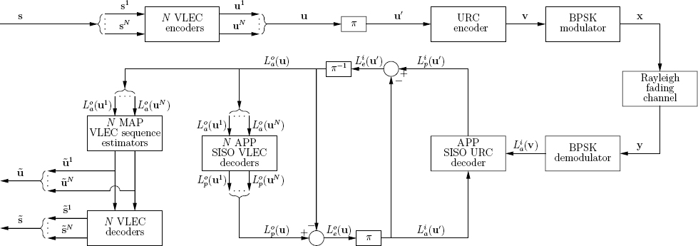
Recall that the BBIrVLC-TCM scheme of Section 7.3 employed a high number of transmission sub-frames. In order that these sub-frames could be decoded, it was necessary to explicitly convey their lengths to the receiver as side information. In the proposed IrVLC-URC scheme, we shall attain a significant reduction in the amount of side information that must be conveyed by employing only a single transmission sub-frame per component VLEC codebook.
8.4.1 Joint Source and Channel Coding
As described above, the proposed IrVLC-URC scheme facilitates the near-capacity transmission of source symbols having values with unequal probabilities of occurrence over an uncorrelated narrowband Rayleigh fading channel. In the transmitter of the proposed IrVLC-URC scheme portrayed in Figure 8.6, the source symbol frame s comprises Jsum number of source symbols and is decomposed into N number of sub-frames {sn}nN=1. Each source symbol sub-frame ![]() comprises Jn number of source symbols, where we have
comprises Jn number of source symbols, where we have
Note that the fractions {Cn}nN, where Cn = Jn/Jsum, may be specifically chosen in order to shape the inverted IrVLC EXIT function, as seen in Figures 7.4 and 7.5 of Section 7.3.2.
Each source symbol sub-frame sn is VLEC-encoded using a corresponding component VLEC codebook VLECn, having a particular coding rate R(VLECn) and RV-FDM D(VLECn). The specific source symbols having the value of k ∈ [1 ...K] and encoded by the specific component VLEC codebook VLECn are represented by the codeword VLECn,k, which has a length of In,k bits. The Jn number of VLEC codewords that represent the Jn number of source symbols in each particular source symbol sub-frame sn are concatenated to provide the transmission sub-frame ![]() , having a
, having a
bits. Note that these transmission sub-frame lengths will typically vary from frame to frame, owing to the variable lengths of the VLEC codewords.
In order to facilitate the VLEC decoding of each transmission sub-frame un, it is necessary to explicitly convey its length In to the receiver. Furthermore, this highly error-sensitive side information must be reliably protected against transmission errors. This may be achieved using a low-rate block code, for example. For the sake of avoiding obfuscation, this is not shown in Figure 8.6. In Section 8.5.5 we comment on the amount of side information that is required for reliably conveying the specific number of bits in each transmission sub-frame to the decoder. As described above, however, we may expect this to be significantly less than the amount of side information required in the BBIrVLC-TCM scheme of Section 7.2.
In the scheme’s transmitter, the N transmission sub-frames {un}nN are concatenated, as shown in Figure 8.6. The resultant transmission frame u has a length of ![]() bits. Note that each component VLEC codebook VLECn generates a fraction αn = In/Isum of the transmission frame u.
bits. Note that each component VLEC codebook VLECn generates a fraction αn = In/Isum of the transmission frame u.
Following IrVLC encoding, the bits of the transmission frame u are interleaved in the block π of Figure 8.6 in order to provide the interleaved transmission frame u′. This is URC encoded in order to obtain the URC-encoded frame v, and BPSK modulation is employed to generate the channel’s input symbols x, as shown in Figure 8.6. These symbols are transmitted over an uncorrelated narrowband Rayleigh fading channel and are received as the channel’s output symbols y, as seen in Figure 8.6.
8.4.2 Iterative Decoding
In the receiver of Figure 8.6, APP SISO URC and VLEC decoding are performed iteratively. As usual, extrinsic soft information, represented in the form of LLRs [292], is iteratively exchanged between the URC and VLEC decoding stages for the sake of assisting each other’s operation [275,278], as described in Section 4.3. In Figure 8.6, L(.) denotes the LLRs of the bits concerned, where the superscript i indicates inner URC decoding, while o corresponds to outer VLEC decoding. Additionally, a subscript denotes the dedicated role of the LLRs, with a, p and e indicating a priori, a posteriori and extrinsic information respectively.
During each decoding iteration, the inner URC decoder is provided with a priori LLRs pertaining to the interleaved transmission frame Lai(u′), as shown in Figure 8.6. These LLRs are gleaned from the most recent iteration of the outer VLEC decoding stage’s operation, as highlighted below. In the case of the first decoding iteration, no previous VLEC decoding has been performed and hence the a priori LLRs Lpi(u′) provided for URC decoding are all zero valued, corresponding to a probability of 0.5 for both ‘0’ and ‘1.’ Given the a priori LLRs Lai(v) provided by the soft BPSK demodulator and the a priori LLRs Lp>i(u′), as shown in Figure 8.6.
During iterative decoding it is necessary to prevent the reuse of already exploited information, since this would limit the attainable iteration gain [296], as described in Section 4.2. This is achieved following URC decoding by the subtraction of Lai(u′) from Lpi(u′), as observed in Figure 8.6. The resultant extrinsic LLRs Lpi(u′) are de-interleaved in the block π−1 and forwarded as a priori LLRs to the VLEC decoder. As described in Section 4.3, interleaving is employed in order to mitigate correlation within the a priori LLR frames. This is necessary since the BCJR algorithm assumes that all a priori LLRs that can influence any particular decoding decision are uncorrelated.
Since N separate VLEC encoding processes are employed in the proposed scheme’s transmitter, N separate VLEC decoding processes are employed in its receiver. In parallel with the composition of the bit-based transmission frame u from its N sub-frames, the a priori LLRs Lao(u′) are decomposed into N sub-frames, as seen in Figure 8.6. This is achieved with the aid of the explicit side information that conveys the number of bits In in each transmission sub-frame un. Each of the N VLEC decoding processes is provided with the a priori LLR sub-frame Lpo (un) and in response it generates the a posteriori LLR sub-frame Lpo (un), n ∈ [1 ...N]. These a posteriori LLR sub-frames are concatenated in order to provide the a posteriori LLR frame Lpo(u), as portrayed in Figure 8.6. Following the subtraction of the a priori LLRs Lao(u), the resultant extrinsic LLRs Leo(u) are interleaved and forwarded as a priori information to the next URC decoding iteration.
Following the completion of iterative decoding, each transmission sub-frame un is estimated from the corresponding a priori LLR sub-frame Lao(un). This may be achieved by employing MAP sequence estimation operating on a bit-based trellis structure, as shown in Figure 8.6. The resultant transmission sub-frame estimate ![]() n is VLEC decoded using the corresponding component VLEC codebook VLECn in order to provide the source symbol sub-frame estimate
n is VLEC decoded using the corresponding component VLEC codebook VLECn in order to provide the source symbol sub-frame estimate ![]() , as seen in Figure 8.6. Note that this approach cannot exploit the knowledge that each sub-frame sn comprises a particular number Jn of source symbols. For this reason, the source symbol sub-frame estimate
, as seen in Figure 8.6. Note that this approach cannot exploit the knowledge that each sub-frame sn comprises a particular number Jn of source symbols. For this reason, the source symbol sub-frame estimate ![]() of each source symbol sub-frame sn may or may not contain Jn source symbols. In order that we may prevent the loss of synchronization that this would imply, dummy source symbol estimates are removed from, or appended to the end of, each source symbol sub-frame estimate
of each source symbol sub-frame sn may or may not contain Jn source symbols. In order that we may prevent the loss of synchronization that this would imply, dummy source symbol estimates are removed from, or appended to the end of, each source symbol sub-frame estimate ![]() in order to ensure that they each comprise the correct number of source symbol estimates. Finally, the source symbol frame estimate
in order to ensure that they each comprise the correct number of source symbol estimates. Finally, the source symbol frame estimate ![]() is obtained by concatenating the N source symbol sub-frame estimates, as observed in Figure 8.6.
is obtained by concatenating the N source symbol sub-frame estimates, as observed in Figure 8.6.
8.5 Parameter Design for the Proposed Scheme
In this section we demonstrate the employment of both Algorithm 3.3 of Section 3.3 and the GA of Section 8.3 to design suites of IrVLC component VLEC codebooks. The APP SISO decoding and MAP sequence estimation performances associated with these codebooks are characterized, and we investigate the suitability of the two suites of component VLEC codebooks for use in the IrVLC-URC scheme of Section 8.4. Finally, we detail a number of parameterizations of the IrVLC-URC scheme of Section 8.4, which employ various IrVLC coding rates.
8.5.1 Design of IrVLC Component VLEC Codebook Suites
As described above, both Algorithm 3.3 of Section 3.3 and the GA of Section 8.3 were employed to design suites of IrVLC component VLEC codebooks. All component VLEC codebooks were designed for the encoding of K = 16-ary source symbol values, having the specific probabilities of occurrence that result from the Lloyd–Max quantization [164, 165] of independent Gaussian distributed continuous-valued source samples, as exemplified in Section 7.2.1. These occurrence probabilities of {P(k)}kK=1 = {0.008, 0.024, 0.043, 0.060, 0.076, 0.089, 0.097, 0.102, 0.102, 0.097, 0.089, 0.076, 0.060, 0.043, 0.024, 0.008} can be seen to vary by more than an order of magnitude. Since these probabilities correspond to varying numbers of {− log2(P(k))}kK=1 = {6.93, 5.35, 4.55, 4.05, 3.72, 3.49, 3.36, 3.29, 3.29, 3.36, 3.49, 3.72, 4.05, 4.55, 5.35, 6.93} bits of information per symbol, the application of VLCs is motivated, since the source entropy is E = 3.77 bits of information per symbol, according to Equation (8.2). Furthermore, all component VLEC codebooks were designed to have RV-FDMs, and hence IV-FD lower bounds, of at least two. This ensures that the resultant IrVLC schemes will have inverted EXIT functions that reach the top right-hand corner of the EXIT chart and will therefore support iterative decoding convergence to an infinitesimally low probability of error, as described in Section 4.3.
As argued in Section 8.1, employing Algorithm 3.3 of Section 3.3 to design a suite of component VLEC codebooks having a wide range of inverted EXIT function shapes typically requires a significant amount of ‘trial-and-error’-based human interaction. As we demonstrate in this section, this is avoided when employing the GA of Section 8.3. Hence, in order to ensure a fair comparison, the trial and error was avoided when designing a suite of component VLEC codebooks for use in IrVLCs using Algorithm 3.3 of Section 3.3. Instead, 11 component VLEC codebooks {VLECn}n11=1 having IV-FD lower bounds given by ![]() (VLECn)= n + 1 ∀n ∈ [1 ...11] were generated. This was achieved in accordance with Equation (8.5) by specifying a target minimum block distance of
(VLECn)= n + 1 ∀n ∈ [1 ...11] were generated. This was achieved in accordance with Equation (8.5) by specifying a target minimum block distance of
a target minimum divergence distance of
and a target minimum convergence distance of
This approach is not labor-intensive, but results in a suite of component VLEC codebooks having only a limited variety of inverted EXIT function shapes, as will be shown in Section 8.5.2. The coding rate R(VLECn), RV-FDM D(VLECn) and the composition of each resultant component VLEC codebook VLECn is provided in Table 8.4. Note that, in all cases, the VLEC-encoded bit entropy E(VLECn) was found to be only a negligible distance away from unity.
Table 8.4: Properties and composition of the 11 component VLEC codebooks {VLECn}n11=1 designed using Algorithm 3.3 of Section 3.3
| VLECn | Properties† | Composition‡ |
| VLEC1 | (0.956, 2.395) | 6,6,5,5,4,4,3,3,3,3,4,4,5,5,6,6, E97E2BD3314A4F1321 |
| VLEC2 | (0.637, 3.786) | 9,8,7,7,6,6,6,5,4,5,6,6,7,7,7,8, 3EBBB53335228C1853E597BAFB |
| VLEC3 | (0.603, 4.354) | 10,10,9,8,7,6,5,4,4,5,6,7,8,8,9,10, 9AA5CA652B36B3E065564E5554E65 |
| VLEC4 | (0.468, 5.775) | 12,11,10,9,9,8,8,6,5,7,8,9,9,10,11,12, 8DC2F2F996FDB346A3815B72DA394EEFC4FF |
| VLEC5 | (0.446, 6.388) | 12,12,11,10,10,9,7,6,6,7,8,9,10,11,11,12, 2D917354DA4CDC9A71FC01CACCB694ED6233A9 |
| VLEC6 | (0.376, 7.815) | 14,13,12,12,11,10,9,8,7,9,10,11,11,12,13,13, 56D59BBBD526C778ACB683C00D4E69D35594EBAD8663 |
| VLEC7 | (0.371, 8.331) | 13,13,12,12,11,10,9,8,8,9,10,11,12,12,13,13, C959B2B1AA8D5A9B65E1FF000F29A6B1664F198E9395 |
| VLEC8 | (0.311, 9.523) | 17,16,15,14,13,12,11,10,8,11,12,13,14,15,16,16, 16CEAAE7BB6CB5D2BB5DF1AE68F800CEB4E735DB29F51E7AD4D5EA |
| VLEC9 | (0.308, 10.359) | 17,16,15,14,13,12,11,10,9,11,12,13,14,15,16,17, 1E7E727198F26E57CE7A6D5E41F002C6BCB4D72ED5AD732EE3ABA7 |
| VLEC10 | (0.267, 11.512) | 19,18,17,16,15,14,13,12,11,12,14,15,16,17,18,19, 3560BB748EDE0D768C5B9AEAB1CE01F8007C1E5 636CAAAD6E73653E1CD66F4 |
| VLEC11 | (0.265, 12.404) | 19,18,17,16,15,14,13,12,11,13,14,15,16,17,18,19, 35EB5B3BC1D9DAEB73994EB37CF183F00038E2D 9276B2FD1B6736BDA6AE3E8 |
†The properties of each component VLEC codebook VLECn are provided using the format (R(VLECn), D(VLECn)).
‡The composition of each component VLEC codebook VLECn is specified by providing the K = 16 codeword lengths {In,k}kK=1 together with the hexadecimal representation of the ordered concatenation of the K = 16 VLEC codewords {VLECn,k}kK=1 in the codebook.
Similarly, the GA of Section 8.3 was employed to generate a suite of 11 component VLEC codebooks {VLECn}n22=12. However, this suite comprises two categories of component VLEC codebook, namely {VLECn}n18=12 and {VLECn}n22=19. We demonstrate in Section 8.5.2 that these two categories provide some component VLEC codebooks having RV-FDMs that correspond to ‘S’-shaped inverted EXIT functions having two points of inflection and some that have only one point of inflection, as described in Section 8.2. More specifically, the GA attempted to maximize the RV-FDM D(VLEC) in order to provide ‘S’-shaped inverted EXIT functions having two points of inflection during the generation of the first seven component VLEC codebooks {VLECn}n18=12, having coding rates R(VLEC) in the range of [0.25, 0.95]. In contrast, during the generation of the remaining four component VLEC codebooks {VLECn}n22=19, which have coding rates R(VLEC) in the range of [0.25, 0.65], RV-FDMs D(VLEC) as close to, but no less than, two were sought in order to provide inverted EXIT functions that have only one point of inflection. Naturally, maximal VLEC-encoded bit entropies and minimal bit-based trellis complexities were sought in all cases. The GA parameters employed to design the two categories of component VLEC codebooks {VLECn}n18=12 and {VLECn}n22=19 are detailed in Table 8.5. Note that the specified coding rates were chosen in order to provide a suite of component VLEC codebooks having a wide variety of inverted EXIT function shapes.
Table 8.5: Parameters employed by the proposed GA during the generation of the 11 component VLEC codebooks {VLECn}22=1 (the variables are defined in Table 8.5)

During all iterations of the GA, a target list length of Ltar= 1000 was employed. Furthermore, in order to limit the GA’s complexity, the value of Nmax was set only just high enough to ensure that the list length reached Ltar= 1000.
Finally, the generation of component VLEC codebooks using the GA of Section 8.3 was divided into two phases.
During the first phase of the GA’s operation, each parent VLEC codebook VLEC0 was provided by one of the codebooks designed using Algorithm 3.3 of Section 3.3 {VLECn}n11=1, as shown in Table 8.5. More specifically, for each of the seven component VLEC codebooks {VLECn}n18=12, the heuristically designed VLEC codebook from {VLECn}n11=1 having the coding rate R(VLEC) that is closest to, but not lower than, the target coding rate Rlim was employed as the parent codebook VLEC0. By contrast, the high-rate VLEC codebook VLEC1 was employed as the parent codebook during the generation of each of the four component VLEC codebooks {VLECn}n22=19
Note that each first phase of the GA’s operation was employed to provide a VLEC codebook VLEC having an optimized RV-FDM D(VLEC) and a coding rate R(VLEC) that is reduced from that of the parent code VLEC0 towards the target coding rate Rlim. This was achieved using the parameter values of αD = 1 and αR = αE = αT = 0. Note that whilst this specific choice of the parameters appears to optimize only the RV-FDM D(VLEC), this naturally results in a reduced coding rate R(VLEC), as desired.
Table 8.6: Properties and composition of the 11 component VLEC codebooks {VLECn}n=1222 designed using the GA of Section 8.3
| VLECn | Properties† | Composition‡ |
| VLEC12 | (0.950, 2.412) | 6,6,5,5,3,4,3,3,3,4,4,4,5,5,6,6, 317E29FEA2490F1EA1 |
| VLEC13 | (0.850, 2.617) | 6,7,5,5,4,4,3,3,5,4,4,5,5,6,7,8, 140DE2BCB304A54F6D818 |
| VLEC14 | (0.750, 2.793) | 7,8,7,6,6,4,5,4,5,4,5,3,6,5,8,7, 1761E3F330FB2A494F8AD1C |
| VLEC15 | (0.650, 2.981) | 7,7,8,7,7,5,6,4,6,4,6,5,6,7,8,7, 3540C30FF578C04E753C1862D |
| VLEC16 | (0.501, 4.807) | 13,11,9,11,7,8,6,5,5,6,8,7,9,11,12,13, 13192CCD6E0F556B3F80CA55438997333A69 |
| VLEC17 | (0.350, 8.475) | 15,14,16,14,12,10,9,8,8,9,10,11,13,13,15,16, 1522D8CA63D49CD714DB2F0FF8007A4D358B39A 6353669C2B |
| VLEC18 | (0.251, 12.449) | 25,18,17,16,15,14,13,12,11,13,14,15,28,17,18,19, 1670497B3BC1D9DAEB73994EB37CF183F00038E 2D9276B2CE0FB5B6736BDA6AE3E8 |
| VLEC19 | (0.653, 2.269) | 14,11,11,7,9,5,3,3,3,3,5,7,5,9,16,12, 1558553AA17EA7350C850E542AB42AA |
| VLEC20 | (0.501, 2.133) | 11,17,8,8,9,5,6,2,2,3,12,18,5,15,11,14, 0DA1B6DCD0DCD843181B61B6D8736D86DCDB7 |
| VLEC21 | (0.350, 2.155) | 13,19,7,17,10,10,7,3,3,3,13,37,6,16,16,24, 36D1B6D9346DB7368D932C536C9B6D804764936 D936DA36DB01 |
| VLEC22 | (0.252, 2.117) | 8,14,8,9,12,6,5,2,3,2,56,62,5,15,11,11, 06E6DB9A1B0DB0C22236DB34343BEB6C36DB343 43BEB6DB0E6DB0DB9B4 |
†The properties of each component VLEC codebook VLECn are provided using the format (R(VLECn), D(VLECn)).
‡ The composition of each component VLEC codebook VLECn is specified by providing the K = 16 codeword lengths {In,k}Kk=1, together with the hexadecimal representation of the ordered concatenation of the K = 16 VLEC codewords {VLECn,k}Kk=1 in the codebook.
During the second phase of the GA’s operation, the result of the first phase was employed as the parent code VLEC0. Furthermore, the parameter values of αD = 6, αR = 2, αE = 3 and αT = 1 were employed in order to jointly optimize the resultant RV-FDM D(VLEC), the coding rate R(VLEC), the VLEC-encoded bit entropy E(VLEC) and the bit-based trellis complexity T(VLEC). The coding rates, the RV-FDMs and the composition of the 11 resultant component VLEC codebooks are provided in Table 8.6. Note that in all cases the VLEC-encoded bit entropy E(VLECn) was found to be only a negligible distance away from unity. Rather than providing the bit-based trellis complexity T(VLECn) of each component VLEC codebook VLECn, we consider the computational complexity associated with APP SISO decoding and MAP sequence estimation in Section 8.5.2.
8.5.2 Characterization of Component VLEC Codebooks
In this section we characterize the component VLEC codebooks of the two suites that were introduced in Section 8.5.1, which were designed using Algorithm 3.3 of Section 3.3 and the GA of Section 8.3. More specifically, we consider both the APP SISO decoding and the MAP sequence estimation performances that are associated with these component VLEC codebooks.
The APP SISO decoding and MAP sequence estimation performances of the component VLEC codebooks {VLECn}n22=1 were investigated by simulating the VLEC encoding and decoding of 100 frames of 10 000 randomly generated source symbols. As described in Section 8.5.1, these source symbols have K = 16 -ary values with the specific probabilities of occurrence that result from the Lloyd–Max quantization of independent Gaussian distributed source samples. The corresponding frames of VLEC-encoded bits were employed to generate uncorrelated Gaussian distributed a priori LLR frames having a range of mutual informations Ia ∈ [0,E(VLEC)], where E(VLEC) is the VLEC-encoded bit entropy of the VLEC codebook VLEC. Note that the VLEC-encoded bit entropy E(VLEC) was found to be only at a negligible distance from unity in the case of all the component VLEC codebooks considered, as described in Section 8.5.1. During APP SISO decoding and MAP sequence estimation, all calculations were performed in the logarithmic probability domain, while using an eight-entry lookup table for correcting the Jacobian approximation in the Log-MAP algorithm [296]. This approach requires only ACS computational operations, which will be used as our computational complexity measure, since this is characteristic of the complexity/area/speed trade-offs in systolic-array-based chips.
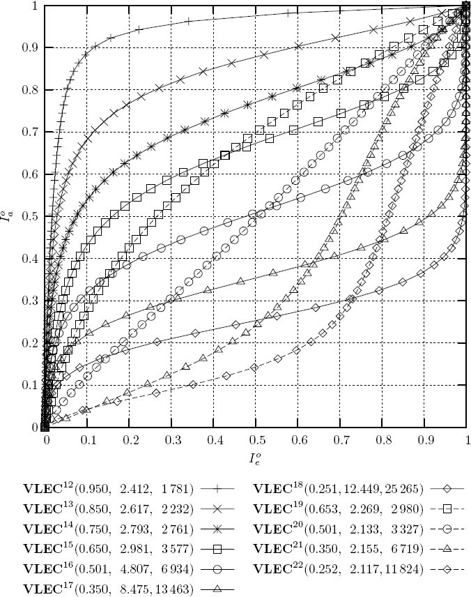
The APP SISO decoding performances of the component VLEC codebooks designed using Algorithm 3.3 of Section 3.3 and the GA of Section 8.3 are characterized by the inverted EXIT functions of Figures 8.7 and 8.8 respectively. Here, all mutual information measurements were made using the histogram-based approximation of the LLR Probability Density Functions (PDFs) [294]. For each considered VLEC codebook VLEC, the coding rate R(VLEC) and RV-FDM D(VLEC) are provided in Figures 8.7 and 8.8. Furthermore, the computational complexity of APP SISO decoding is characterized by the average number OAPP (VLEC) of ACS operations performed per source symbol.
As shown in Figure 8.7, the suite of component VLEC codebooks {VLECn}n=111 generated using Algorithm 3.3 of Section 3.3 provides only a limited variety of ‘S’ shaped inverted EXIT functions having as many as two points of inflection, as predicted in Section 8.5.1. These ‘S’-shaped functions are generated by the HA when seeking a minimal coding rate for a particular IV-FD lower bound, which results in a relatively high RV-FDM for that specific coding rate, as described in Section 8.2. By contrast, the GA of Section 8.3 provided a suite of component VLEC codebooks {VLECn}n=122 having the wide variety of inverted EXIT function shapes shown in Figure 8.8, some having an ‘S’ shape with as many as two points of inflection, while others have no more than one point of inflection, as predicted in Section 8.5.1.
Figure 8.7: Inverted EXIT functions characterizing the APP SISO decoding performance of the component VLEC codebooks that were designed using Algorithm 3.3 of Section 3.3. Functions are labeled using the format VLEC (R(VLEC), D(VLEC), OAPP (VLEC)). ©IEEE [200] Maunder and Hanzo, 2008.

Note that for all component VLEC codebooks having relatively high RV-FDMs {VLECn}18n=1, the RV-FDM D(VLEC) can be seen to increase as the coding rate R(VLEC) decreases. By contrast, the RV-FDM D(VLEC) can be seen to decrease as the coding rate R(VLEC) decreases in the case of the component VLEC codebooks {VLECn}n22=19 designed using the GA of Section 8.3 to have minimized RV-FDMs. These results can be explained by the increased degree of design freedom that is facilitated by having reduced coding rates R(VLEC). Finally, note that all inverted EXIT functions of Figures 8.7 and 8.8 reach the (1,1) point of the EXIT chart, since all component VLEC codebooks {VLECn}n22=1 have RV-FDMs D(VLEC) and hence IV-FD lower bounds ![]() (VLEC) of at least two [298], as described in Section 4.3.
(VLEC) of at least two [298], as described in Section 4.3.
Figure 8.8: Inverted EXIT functions characterizing the APP SISO decoding performance of the component VLEC codebooks that were designed using the GA of Section 8.3. Functions are labeled using the format VLEC (R(VLEC), D(VLEC), OAPP(VLEC)).
Let us now consider the MAP sequence estimation performance that is associated with each component VLEC codebook designed by Algorithm 3.3 of Section 3.3 and the GA of Section 8.3. This may be achieved by evaluating the BER between the transmission sub-frame un and the transmission sub-frame estimate ![]() n that is obtained following the consideration of the a priori LLR sub-frame Lao(un) by the corresponding VLEC MAP sequence estimator of Figure 8.6. Note that we opted for employing the BER associated with the transmission sub-frame estimate
n that is obtained following the consideration of the a priori LLR sub-frame Lao(un) by the corresponding VLEC MAP sequence estimator of Figure 8.6. Note that we opted for employing the BER associated with the transmission sub-frame estimate ![]() n as our performance metric, rather than the Symbol-Error Ratio (SER) associated with the source symbol sub-frame estimate
n as our performance metric, rather than the Symbol-Error Ratio (SER) associated with the source symbol sub-frame estimate ![]() . This is because, owing to the nature of VLEC codes, synchronization can be occasionally lost during the error-infested reconstruction of some source symbol frame estimates, resulting in a particularly poor SER [179]. Hence, the transmission of a prohibitively high number of source symbol frames would have to be simulated in order that the SER could be averaged and employed as a reliable performance metric. Plots of the BER attained during our simulations versus the mutual information Ioa associated with the a priori LLR sub-frame Loa(un) are provided in Figures 8.9 and 8.10 for the component VLEC codebooks designed by Algorithm 3.3 of Section 3.3 and the GA of Section 8.3 respectively. For each specific VLEC codebook VLEC, the coding rate R(VLEC) and RV-FDM D(VLEC) are also provided in Figures 8.9 and 8.10. Furthermore, the computational complexity of MAP sequence estimation is characterized by the average number OMAP(VLEC) of ACS operations performed per source symbol. As may be expected, the MAP sequence estimator’s computational complexities recorded in Figures 8.9 and 8.10 are lower than those of APP SISO decoding, as recorded in Figures 8.7 and 8.8.
. This is because, owing to the nature of VLEC codes, synchronization can be occasionally lost during the error-infested reconstruction of some source symbol frame estimates, resulting in a particularly poor SER [179]. Hence, the transmission of a prohibitively high number of source symbol frames would have to be simulated in order that the SER could be averaged and employed as a reliable performance metric. Plots of the BER attained during our simulations versus the mutual information Ioa associated with the a priori LLR sub-frame Loa(un) are provided in Figures 8.9 and 8.10 for the component VLEC codebooks designed by Algorithm 3.3 of Section 3.3 and the GA of Section 8.3 respectively. For each specific VLEC codebook VLEC, the coding rate R(VLEC) and RV-FDM D(VLEC) are also provided in Figures 8.9 and 8.10. Furthermore, the computational complexity of MAP sequence estimation is characterized by the average number OMAP(VLEC) of ACS operations performed per source symbol. As may be expected, the MAP sequence estimator’s computational complexities recorded in Figures 8.9 and 8.10 are lower than those of APP SISO decoding, as recorded in Figures 8.7 and 8.8.
Figure 8.9: Plots of BER versus a priori mutual information characterizing the Iao characterizing the MAP sequence estimation performance of the component VLEC codebooks that were designed using Algorithm 3.3 of Section 3.3. Plots are labeled using the format VLEC (R(VLEC), D(VLEC), OMAP(VLEC)).
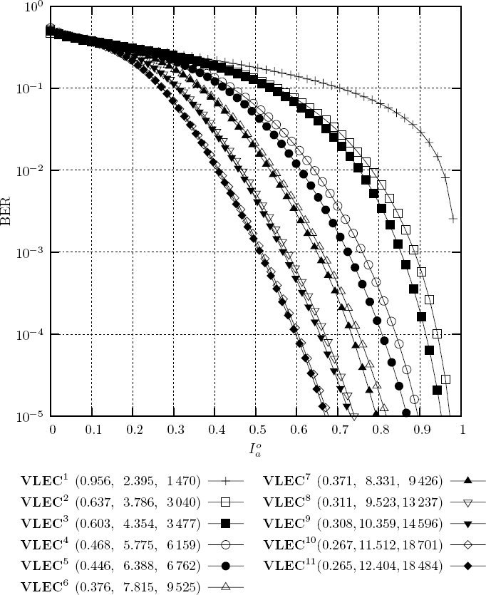
Observe in Figures 8.9 and 8.10 that for all component VLEC codebooks having relatively high RV-FDMs {VLECn}18n=1, the BER performance can be seen to improve as the coding rate R(VLEC) decreases, as may be expected. Note however that a poor BER performance can be seen in Figure 8.10 for the minimized RV-FDM component VLEC codebooks {VLECn}22n=19 generated using the GA of Section 8.3. As a result, an IrVLC scheme comprising the component VLEC codebooks {VLECn}22n=12 can be expected to have a worse BER performance than that designed using the components {VLECn}11n=1. However, we concluded in Chapter 7 that the computational complexity associated with continuing iterative decoding until we achieve perfect convergence at the (1,1) point of the EXIT chart is justified, since an infinitesimally low BER is achieved. Hence the poor BER performance of the minimized RV-FDM component VLEC codebooks {VLECn}22n=19 becomes irrelevant, since it is circumvented.
Figure 8.10: Plots of BER versus a priori mutual information Iao characterizing the MAP sequence estimation performance of the component VLEC codebooks that were designed using the GA of Section 8.3. Plots are labeled using the format VLEC (R(VLEC), D(VLEC), OMAP(VLEC)).

Figure 8.11: LFSR encoder schematic for the recursive URC codec employing a coding memory of LURC = 3.

Let us now comment on the APP SISO decoding and MAP sequence estimation computational complexities that are associated with the component VLEC codebooks of Section 8.5.1, as recorded in Figures 8.7–8.10. Observe that for all the specific component VLEC codebooks {VLECn}18n=1 having relatively high RV-FDMs, the computational complexity of both the APP SISO decoding and the MAP sequence estimation can be seen to increase as the coding rate is reduced. This is due to the higher codeword lengths and hence the increased number of bit-based trellis transitions that are required at reduced coding rates. Whilst the computational complexities associated with the component VLEC codebooks {VLECn}22n=19 having relatively low RV-FDMs also increase as the corresponding coding rates are reduced, these are lower than those of the codebooks {VLECn}18n=1 having relatively high RV-FDMs. Owing to the presence of these low-complexity components within the suite of component VLEC codebooks {VLECn}22n=12 generated using the GA of Section 8.3, a corresponding IrVLC scheme can be expected to have a lower computational complexity than one designed using the components {VLECn}11n=1 generated using Algorithm 3.3 of Section 3.3.
8.5.3 Suitability of IrVLC Component Codebook Suites
Let us now consider the suitability of the component VLEC codeword suites of Section 8.5.1 designed using Algorithm 3.3 of Section 3.3 and the GA of Section 8.3 for near-capacity IrVLC coding in the proposed IrVLC-URC scheme of Section 8.4. In this scheme, an outer IrVLC codec having a parameterized composite coding rate of RIrVLC is serially concatenated with an inner URC codec, which has a coding rate of RURC = 1 by definition. Here, MBPSK = 2-ary Phase-Shift Keying (PSK), or BPSK, modulation is employed for transmission over an uncorrelated narrowband Rayleigh fading channel, as described in Section 8.4. Note that the effective throughput η = RIrVLC · RURC · log2(MBPSK) of the IrVLC-URC scheme is equal to the composite IrVLC coding rate RIrVLC, since RURC = log2(MBPSK) = 1. We opted for employing the Linear Feedback Shift Register (LFSR) structure shown in Figure 8.11 for our URC encoder. This employs a coding memory of LURC = 3 and recursive feedback, as shown in Figure 8.11. Note that a recursive URC codec was chosen, since these have EXIT functions that reach the top right-hand corner of the EXIT chart [299], as do all of our component VLEC codebooks. Hence we can expect to achieve an open EXIT-chart tunnel for the proposed IrVLC-URC scheme, if the channel quality is sufficiently high. As discussed in Section 4.3, this implies that iterative decoding convergence to an infinitesimally low probability of error is facilitated, provided that the iterative decoding trajectory approaches the inner and outer EXIT functions sufficiently closely.
A range of Rayleigh fading channel SNRs Ec/N0 ∈ [−3, 16] dB were considered, and in each case appropriate IrVLC schemes were designed using either the suite of component VLEC codebooks {VLECn}11n=1 of Section 8.5.1 that were designed using Algorithm 3.3 of Section 3.3 or the set of {VLECn}22n=12 designed using the GA of Section 8.3. For each IrVLC scheme, the specific fraction αn of the transmission frame u that is generated by each component VLEC codebook VLECn was designed using the EXIT-chart matching algorithm of [149] in order to shape the composite inverted IrVLC EXIT function, as described in Section 8.1. More specifically, the algorithm of [149] ensures that the inverted IrVLC EXIT function does not cross the URC EXIT function corresponding to the particular Rayleigh fading channel SNR Ec/N0. In each case, we recorded the maximum effective throughput η, which ensured that the corresponding inverted EXIT function did not cross the URC’s EXIT function, resulting in an open EXIT-chart tunnel.
Figure 8.12: The maximum effective throughputs η of IrVLC schemes based on the component VLEC codebook suites {VLECn}11n=1 and {VLECn}22n=12 that yield an open EXIT-chart tunnel when serially concatenated with a URC that protects transmission over a BPSK-modulated Rayleigh fading channel having a particular Eb/N0 value.

The recorded effective throughputs η are plotted in Figure 8.12 together with the BPSK-modulated Rayleigh fading channel’s capacity, which dictates the highest possible effective throughput η of the IrVLC-URC scheme that will permit iterative decoding convergence to an infinitesimally low probability of error [133]. Rather than employing the Rayleigh fading channel SNR Ec/N0, Figure 8.12 plots the recorded effective throughputs against Eb/N0, where the transmit energy per bit of source entropy is given as Eb = Ec/η, with Ec specifying the transmit energy per Rayleigh fading channel use and N0 denoting the average noise energy.
As shown in Figure 8.12, the suite of component VLEC codebooks {VLECn}22n=12 that was designed using the GA of Section 8.3 tended to be more suitable for use in IrVLCs than was the set {VLECn}11n=1 designed using Algorithm 3.3 of Section 3.3. In both cases, open EXIT-chart tunnels were created at threshold channel Eb/N0 values that were closer to the capacity bound when lower effective throughputs η were employed. The IrVLC scheme comprising the component VLEC codebooks {VLECn}22n=12 is capable of maintaining open EXIT-chart tunnels for Eb/N0 values within 1 dB of the BPSK-modulated Rayleigh fading channel’s capacity bound for effective throughputs in the range of η ∈ [0.4, 0.86] bits per channel use. By contrast, the IrVLC scheme comprising the component VLEC codebooks {VLECn}11n=1 only becomes capable of maintaining open EXIT-chart tunnels within a substantially higher margin of 4.4 dB away from the channel’s Eb/N0 capacity bound for effective throughputs of up to 0.86 bits per channel use. Furthermore, this arrangement is unable to maintain open EXIT-chart tunnels for effective throughputs below 0.55 bits per channel use, as shown in Figure 8.12.
The relatively good performance of the IrVLC scheme comprising the component VLEC codebooks {VLECn}22n=12 may be explained by the wide variety of the corresponding inverted component EXIT functions, some having ‘S’ shapes with as many as two points of inflection, whilst others have no more than one point of inflection, as shown in Figure 8.8. This facilitates accurate EXIT-chart matching to a wide range of inner decoder EXIT function shapes. By contrast, the IrVLC scheme comprising the component VLEC codebooks {VLECn}11n=1 is associated with the more limited variety of inverted component EXIT function shapes shown in Figure 8.7.
8.5.4 Parameterizations of the Proposed Scheme
In this section we detail four parameterizations of the IrVLC-URC scheme introduced in Section 8.4. The IrVLC scheme of two of these parameterizations is based upon the suite of component VLEC codebooks {VLECn}11n=1 that was designed using Algorithm 3.3 of Section 3.3, as detailed in Section 8.5.1. The other two parameterizations employ the suite of component VLEC codebooks {VLECn}22n=12 that was designed using the GA of Section 8.3. In each pair of parameterizations, one employs an IrVLC coding rate of RIrVLC = 0.85, whilst the other employs RIrVLC = 0.55. This will therefore illustrate the effect that the IrVLC coding rate has upon the associated APP SISO decoder’s sensitivity to correlation within the a priori LLR frame Loa(u), as described in Section 8.1. We refer to our four parameterizations as the ({VLECn}11n=1, RIrVLC = 0.85), ({VLECn}22n=12, RIrVLC = 0.85), ({VLECn}11n=1, RIrVLC = 0.55) and ({VLECn}22n=12, RIrVLC = 0.55) arrangements accordingly.
For each parameterization, the EXIT-chart matching algorithm of [149] was employed to shape the inverted IrVLC EXIT function under the constraint of achieving the above-mentioned IrVLC coding rates RIrVLC. In each case, the lowest Rayleigh fading channel Eb/N0 value for which an open EXIT-chart tunnel may be created was recorded. In Figure 8.12, these threshold Eb/N0 values are employed to plot the parameterizations’ effective throughputs η, which are equal to the IrVLC coding rates RIrVLC, as described in Section 8.5.3.
As shown in Figure 8.12, the EXIT-chart matching algorithm of [149] was capable of achieving an open EXIT-chart tunnel for the ({VLECn}11n=1, RIrVLC = 0.85) and ({VLECn}22n=12, RIrVLC = 0.85) arrangements at threshold channel Eb/N0 values of 11.54 dB and 7.94 dB respectively. As described in Section 4.3, an open EXIT-chart tunnel implies that iterative decoding at an infinitesimally low probability of error can be achieved, if the iterative decoding trajectory approaches the inner and outer codecs’ EXIT functions sufficiently closely. The threshold channel Eb/N0 value of the ({VLECn}11n=1, RIrVLC = 0.85) arrangement is 4.3 dB away from the capacity bound of 7.24 dB, as shown in Figure 8.12. As argued in Section 8.5.3, this relatively high discrepancy is a consequence of having a poor variety of inverted component EXIT functions in the suite {VLECn}11n=1. By contrast, the threshold channel Eb/N0 value of the ({VLECn}22n=12, RIrVLC = 0.85) arrangement is only 0.7 dB from the channel’s capacity bound, owing to the wide variety of inverted component EXIT functions in the suite {VLECn}22n=12. With reference to Figure 8.12, note that the parameterizations employing an IrVLC coding rate of RIrVLC = 0.85 demonstrate the potential gain that is offered by employing the suite of component VLEC codebooks {VLECn}22n=12 that was designed using the GA of Section 8.3 instead of the suite {VLECn}11n=11 that was generated using Algorithm 3.3 of Section 3.3.
Similarly, an open EXIT-chart tunnel was created for the ({VLECn}11n=1, RIrVLC = 0.55) and ({VLECn}22n=12, RIrVLC = 0.55) arrangements at threshold channel Eb/N0 values of 3.37 dB and 2.79 dB respectively, as shown in Figure 8.12. Whilst the threshold Eb/N0 value of the ({VLECn}11n=1, RIrVLC = 0.55) arrangement is 1 dB from the channel’s capacity bound of 2.37 dB, that of the ({VLECn}22n=12, RIrVLC = 0.55) arrangement is just 0.42 dB away, as shown in Figure 8.12. With reference to Figure 8.12, note that the nearest-capacity threshold Eb/N0 values result when employing an IrVLC coding rate of RIrVLC = 0.55 both for the suite of component VLEC codebooks {VLECn}22n=12 that was designed using the GA of Section 8.3 and for the suite {VLECn}11n=1 that was generated using Algorithm 3.3 of Section 3.3.
Note that the 0.5 dB discrepancy between the threshold channel Eb/N0 values and the capacity bounds of the IrVLC-TCM schemes of Section 7.3.2 are similar to those of the ({VLECn}22n=12, RIrVLC = 0.85) and ({VLECn}22n=12, RIrVLC = 0.55) arrangements, which are 0.7 dB and 0.42 dB respectively. This may be expected, because, like these parameterizations, the IrVLC-TCM schemes of Section 7.3.2 employed a suite of component VLC codebooks having a wide variety of inverted EXIT function shapes.
As described in Section 8.5.3, the EXIT-chart matching algorithm of [149] shaped the inverted IrVLC EXIT functions of our four IrVLC-URC scheme parameterizations by appropriately selecting the fraction Cn of the source symbol frame s and the fraction αn of the transmission frame u that is encoded by each component VLEC codebook VLECn. These fractions are summarized for the ({VLECn}11n=1, RIrVLC = 0.85) and the ({VLECn}11n=1, RIrVLC = 0.55) arrangements in Table 8.7 and for the ({VLECn}22n=12, RIrVLC = 0.85) and the ({VLECn}22n=12, RIrVLC = 0.55) arrangements in Table 8.8.
Let us now discuss the properties of each parameterization’s activated component VLEC codebooks. These are employed to encode a nonzero fraction Cn of the source symbol frame s, and, hence, a nonzero fraction αn of the transmission frame u. Observe in Tables 8.7 and 8.8 that in the ({VLECn}11n=1, RIrVLC = 0.85), ({VLECn}22n=12, RIrVLC = 0.85) and ({VLECn}11n=1, RIrVLC = 0.55) arrangements, each activated component VLEC codebook VLECn has a RV-FDM D(VLECn) that may be considered to be high for its coding rate R(VLECn), as described in Section 8.5.1. By contrast, in the ({VLECn}22n=12, RIrVLC = 0.55) arrangement, the particular activated component VLEC codebooks VLEC20 and VLEC22 have RV-FDMs that may be considered to be low for their coding rates, as shown in Table 8.8. The consequences of this are discussed below.
Table 8.7: Properties of the 11 component VLEC codebooks {VLECn}11n=1 designed using Algorithm 3.3 of Section 3.3, together with the fractions {Cn}11n=1 of the source symbol frame s and the fractions {αn}11n=1 of the transmission frame u that they encode in both the ({VLECn}11n=1, RIrVLC = 0.85) and the ({VLECn}11n=1, RIrVLC = 0.55) arrangements of the IrVLC-URC scheme

† The properties of each component VLEC codebook VLECn are provided using the format (R(VLECn), D(VLECn)).
‡ The fractions are specified using the format (Cn, αn).
The inverted IrVLC EXIT functions of the four IrVLC-URC parameterizations are provided in Figure 8.13, together with the URC EXIT functions corresponding to the threshold channel Eb/N0 values. The inverted IrVLC EXIT functions were generated by simulating the APP SISO decoding of 100 frames of 10 000 randomly generated source symbols. Meanwhile, the URC EXIT functions were generated by simulating the APP SISO decoding of 100 frames of 10 000 randomly generated bits. Here, Gaussian distributed a priori LLR values were employed and all mutual information measurements were made using the histogram-based approximation of the LLR PDFs [294]. During IrVLC and URC APP SISO decoding, all calculations were performed in the logarithmic probability domain, while using an eight-entry lookup table for correcting the Jacobian approximation in the Log-MAP algorithm [296]. This approach requires only ACS operations, which will be used as our computational complexity measure, since this is characteristic of the complexity/area/speed trade-offs in systolic-array-based chips. Figure 8.13 therefore also provides the average number OAPPIrVLC of ACS operations performed per source symbol during APP SISO IrVLC decoding.
Table 8.8: Properties of the 11 component VLEC codebooks {VLECn}22n=12 designed using the GA of Section 8.3, together with the fractions {Cn}22n=12 of the source symbol frame s and the fractions {αn}22n=12 of the transmission frame u that they encode in both the ({VLECn}22n=12, RIrVLC = 0.85) and the ({VLECn}22n=12, RIrVLC = 0.55) arrangements of the IrVLC-URC scheme
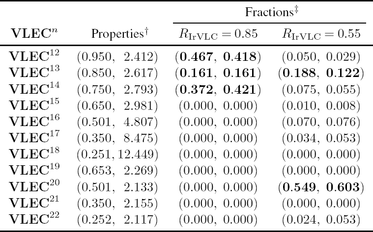
† The properties of each component VLEC codebook VLECn are provided using the format (R(VLECn), D(VLECn)).
‡ The fractions are specified using the format (Cn, αn).
The observed discrepancies between the threshold Eb/N0 values at which open EXIT-chart tunnels emerge and the channel capacity bounds can be explained by considering the EXIT charts seen in Figure 8.13. More specifically, these discrepancies are proportional to the area [204] between the inverted IrVLC EXIT functions and the URC EXIT functions that correspond to the associated threshold Eb/N0 values, as described in Section 5.5. As shown in Figure 8.13, the width of the EXIT-chart tunnel varies along its length for the parameterizations employing the suite of component VLEC codebooks {VLECn}11n=1 designed using Algorithm 3.3 of Section 3.3. In contrast, improved EXIT-chart matches are achieved for the parameterizations employing the suite of component VLEC codebooks {VLECn}22n=12 designed using the GA of Section 8.3, owing to its wide variety of component EXIT functions, as described in Section 8.5.2. For these parameterizations, the EXIT-chart tunnel is narrow in all regions, except when the mutual information Iai of the inner APP SISO URC decoder’s a priori LLR frame Lia(u′) is low. This is because the inner APP SISO URC decoder generates extrinsic LLRs Lie(u) having a nonzero mutual information Ii even when the mutual information Iie of its a priori LLR frame Lia(u′) is zero, as shown in Figure 8.13. By contrast, the inverted EXIT function of the APP SISO IrVLC decoder emerges from a point close to the (0, 0) corner of the EXIT chart, as described in Section 4.3. Note that we could therefore expect to achieve improved EXIT chart matches if the EXIT function of the APP SISO URC decoder could be shaped to start closer to the (0, 0) point of the EXIT chart. This would reduce the area between the inverted IrVLC EXIT function and the URC EXIT function, and hence would result in a reduced discrepancy between the threshold Eb/N0 value and the channel capacity bound.
Figure 8.13: EXIT charts for the parameterizations of the IrVLC-URC scheme, characterizing the IrVLC and URC APP SISO decoding performance: (a) ({VLECn}11n=1, RIrVLC = 0.85) arrangement; (b) ({VLECnn=12, RIrVLC = 0.85) arrangement; (c) ({VLECn}11n=1, RIrVLC = 0.55) arrangement; (d) ({VLECn}22n=12, RIrVLC = 0.55) arrangement. The inverted IrVLC EXIT functions are labeled using the format {VLECn} (RIrVLC, OAPPIrVLC). The URC EXIT functions are provided for the threshold channel Eb/N0 values, as specified in the URC EXIT function labels.
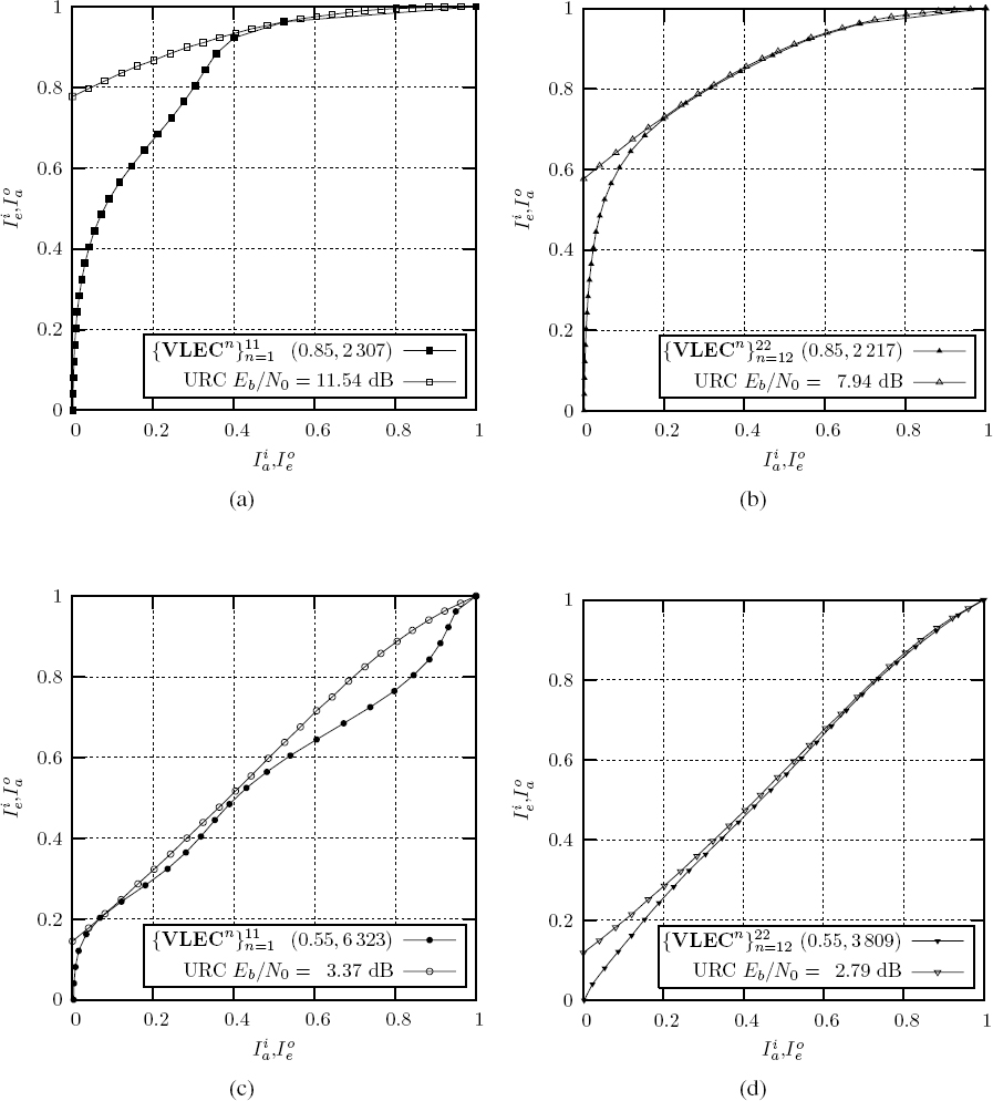
Note that the ({VLECn}22n=12, RIrVLC = 0.55) arrangement’s narrow EXIT-chart tunnel of Figure 8.13d is facilitated by the activation of the particular component VLEC codebooks VLEC20 and VLEC22, as shown in Table 8.8. This is because these component VLEC codebooks have low RV-FDMs and are therefore associated with inverted EXIT functions having no more than a single point of inflection, as shown in Figure 8.8 and described in Section 8.2. This is in contrast to the ({VLECn}11n=1, RIrVLC = 0.55) arrangement, which activates component VLEC codebooks that are associated with inverted EXIT functions having up to two points of inflection, as shown in Table 8.7. As a result, the composite inverted IrVLC EXIT function of Figure 8.13c has many points of inflection and the width of the EXIT-chart tunnel varies along its length, as described above.
Note that the areas beneath the URC EXIT functions provided in Figure 8.13 were found to be equal to the corresponding channel capacities, which specify the maximum effective throughput for which iterative decoding convergence to an infinitesimally low probability of error is theoretically possible. This is a consequence of the area property of EXIT charts [204] and shows that there is no capacity loss in the IrVLC-URC scheme, as described in Section 5.5. Note that this is in contrast to the schemes of Chapter 7, which employed a RTCM = 3/4-rate TCM inner codec. In this case, the maximum achievable effective throughput was 3 bits per MTCM = 16-ary QAM channel use, whilst the capacity approached 4 bits per channel use for high channel Eb/N0 values, as described in Section 8.1.
Let us now characterize the performance of the IrVLC MAP sequence estimators of each of our four IrVLC-URC parameterizations. This may be achieved by evaluating the BER between the transmission frame u and the transmission frame estimate ![]() that is obtained following the consideration of the a priori LLR frame Loa(u) by the IrVLC MAP sequence estimator of Figure 8.6. Note that we opted for employing the BER associated with the transmission frame estimate
that is obtained following the consideration of the a priori LLR frame Loa(u) by the IrVLC MAP sequence estimator of Figure 8.6. Note that we opted for employing the BER associated with the transmission frame estimate ![]() as our performance metric, rather than the SER associated with the source symbol frame estimate
as our performance metric, rather than the SER associated with the source symbol frame estimate ![]() for the reasons discussed in Section 8.5.2. Plots of the BER versus the mutual information Iao associated with the a priori LLR frame Loa(u) are provided for each of our four IrVLC-URC parameterizations in Figure 8.14. These were obtained by simulating the MAP sequence estimation of 100 frames of 10 000 randomly generated source symbols, using Gaussian distributed a priori LLR values [294]. During MAP sequence estimation, all calculations were performed in the logarithmic probability domain, while using an eight-entry lookup table for correcting the Jacobian approximation in the Log-MAP algorithm [296]. Again, this approach requires only ACS computational operations, which will be used as our computational complexity measure, since this is characteristic of the complexity/area/speed trade-offs in systolic-array-based chips. Figure 8.14 therefore also provides the average number OMAPIrVLC of ACS operations performed per source symbol during IrVLC MAP sequence estimation. As may be expected, the MAP sequence estimation computational complexities recorded in Figure 8.14 are lower than those of APP SISO decoding, as recorded in Figure 8.13.
for the reasons discussed in Section 8.5.2. Plots of the BER versus the mutual information Iao associated with the a priori LLR frame Loa(u) are provided for each of our four IrVLC-URC parameterizations in Figure 8.14. These were obtained by simulating the MAP sequence estimation of 100 frames of 10 000 randomly generated source symbols, using Gaussian distributed a priori LLR values [294]. During MAP sequence estimation, all calculations were performed in the logarithmic probability domain, while using an eight-entry lookup table for correcting the Jacobian approximation in the Log-MAP algorithm [296]. Again, this approach requires only ACS computational operations, which will be used as our computational complexity measure, since this is characteristic of the complexity/area/speed trade-offs in systolic-array-based chips. Figure 8.14 therefore also provides the average number OMAPIrVLC of ACS operations performed per source symbol during IrVLC MAP sequence estimation. As may be expected, the MAP sequence estimation computational complexities recorded in Figure 8.14 are lower than those of APP SISO decoding, as recorded in Figure 8.13.
By comparing plots of Figure 8.14 with those of Figures 8.9 and 8.10, we may observe that the MAP sequence estimation performance of each parameterization is dominated by that associated with a particular one of its activated component VLEC codebooks. In all four cases, the dominant component VLEC codebook is employed to encode a large fraction Cn of the source symbol frame s and has a relatively low RV-FDM, resulting in a poor BER performance, as described in Section 8.5.2. This is because the number of bit errors produced by these codebooks eclipses or dominates those of all other activated component VLEC codebooks. For the (![]() , RIrVLC = 0.85), (
, RIrVLC = 0.85), (![]() , RIrVLC = 0.85), (
, RIrVLC = 0.85), (![]() , RIrVLC = 0.55) and (
, RIrVLC = 0.55) and (![]() , RIrVLC = 5) arrangements, the dominant component VLEC codebooks can be identified as VLEC1, VLEC12, VLEC2 and VLEC20, respectively.
, RIrVLC = 5) arrangements, the dominant component VLEC codebooks can be identified as VLEC1, VLEC12, VLEC2 and VLEC20, respectively.
Figure 8.14: Plots of BER versus a priori mutual information Ioa, characterizing the IrVLC MAP sequence estimation performance in the four IrVLC-URC parameterizations. Plots are labeled using the format {VLECn} (RIrVLC, OMAPIrVLC.

As may be expected, the IrVLC-URC parameterizations employing a coding rate of RIrVLC = 0.55 offered a lower BER at all values of a priori mutual information Ioa than those employing a coding rate of RIrVLC = 0.85, as shown in Figure 8.14. Whilst the two parameterizations employing a coding rate of RIrVLC = 0.85 exhibit similar BER performances, the (![]() RIrVLC = 0.55) arrangement offers a better BER performance than the (
RIrVLC = 0.55) arrangement offers a better BER performance than the (![]() RIrVLC = 0.55) arrangement. This may be attributed to the activation of the component VLEC codebooks that were designed by the GA of Section 8.3 to have minimal RV-FDMs in the (
RIrVLC = 0.55) arrangement. This may be attributed to the activation of the component VLEC codebooks that were designed by the GA of Section 8.3 to have minimal RV-FDMs in the (![]() , RIrVLC = 0.55) arrangement, as predicted in Section 8.5.2. Note however that we concluded in Chapter 7 that the computational complexity associated with continuing iterative decoding until perfect convergence at the (1,1) point of the EXIT chart is achieved may be justified owing to the corresponding infinitesimally low BER achieved. Hence, the poor BER performance of the (
, RIrVLC = 0.55) arrangement, as predicted in Section 8.5.2. Note however that we concluded in Chapter 7 that the computational complexity associated with continuing iterative decoding until perfect convergence at the (1,1) point of the EXIT chart is achieved may be justified owing to the corresponding infinitesimally low BER achieved. Hence, the poor BER performance of the (![]() , RIrVLC = 0.55) arrangement becomes irrelevant.
, RIrVLC = 0.55) arrangement becomes irrelevant.
Let us now comment on both the APP SISO IrVLC decoding and the MAP IrVLC sequence estimation computational complexities that are associated with our four IrVLC-URC parameterizations, as recorded in Figures 8.13 and 8.14. Observe that the IrVLC-URC parameterizations employing a coding rate of RIrVLC = 0.55 are associated with higher computational complexities than those employing a coding rate of RIrVLC = 0.85. This may be explained by the high computational complexities that are associated with the low-rate component VLEC codebooks that are activated in the context of the RIrVLC = 0.55 parameterizations, as detailed in Section 8.5.2. Whilst the two parameterizations employing a coding rate of RIrVLC = 0.85 exhibit similar computational complexities, the (![]() , RIrVLC = 0.55) arrangement incurs lower computational complexities than the (
, RIrVLC = 0.55) arrangement incurs lower computational complexities than the (![]() , RIrVLC = 0.55) parameterization. As predicted in Section 8.5.2, this may be attributed to the activation of the low-complexity component VLEC code-books that were designed by the GA of Section 8.3 to have minimal RV-FDMs in the (
, RIrVLC = 0.55) parameterization. As predicted in Section 8.5.2, this may be attributed to the activation of the low-complexity component VLEC code-books that were designed by the GA of Section 8.3 to have minimal RV-FDMs in the (![]() , RIrVLC = 0.55) arrangement.
, RIrVLC = 0.55) arrangement.
Note that the average number of ACS operations performed per LLR during APP SISO URC decoding was found to be approximately equal to 200 in all parameterizations. This corresponds to an average of OAPPURC = 200 · E/RIrVLC = 887 ACS operations per URC source symbol in the case of the RIrVLC = 0.85 parameterizations and OAPPURC = 1370 ACS operations per source symbol for the RIrVLC = 0.55 parameterizations. By comparing these complexities with those provided in Figures 8.13 and 8.14 for APP SISO IrVLC decoding and MAP IrVLC sequence estimation, we may expect these latter processes to incur between 70% and 80% of the total iterative decoding complexity.
8.5.5 Interleaver Length
We opted for employing an average interleaver length of Isum ≈ 100 000 bits in each of our four IrVLC-URC parameterizations. Since this is less than half as long as the interleaver employed in Chapter 7, we can expect it to mitigate the correlation within the a priori LLR frames Loa(u) and Lia(u′) to a lesser degree, as described in Section 4.3. Hence, this choice of interleaver length will allow us to characterize the effect that the IrVLC coding rate RIrVLC has upon the APP SISO IrVLC decoder’s sensitivity to the aforementioned correlation, as discussed in Section 7.4.3.
In order to achieve an average interleaver length of Isum ≈ 100 000 bits, we must employ source sample frames s comprising the following number of source symbols:
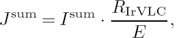
where E = 3.77 bits/symbol is the entropy of the source symbols. Hence, our IrVLC-URC parameterizations having coding rates of RIrVLC = 0.85 and RIrVLC = 0.55 employ source symbol frames comprising Jsum = 22 556 and Jsum = 14 595 symbols, respectively.
As described in Section 8.4.1, each source symbol frame s is decomposed into N = 11 sub-frames in our IrVLC-URC parameterizations. Each source symbol sub-frame sn comprises a specific number Jn ≈ Cn · Jsum of source symbols, according to the fractions Cn specified in Tables 8.7 and 8.8. These fractions are also provided together with the corresponding values of Jn in Tables 8.9 and 8.10 for the parameterizations employing the suite of component VLEC codebooks ![]() designed using Algorithm 3.3 of Section 3.3 and the suite
designed using Algorithm 3.3 of Section 3.3 and the suite ![]() designed using the GA of Section 8.3, respectively. As described in Section 8.4.1, the corresponding component VLEC codebook VLECn is employed to encode each source symbol sub-frame sn, yielding a transmission sub-frame un comprising In number of bits. Since the lengths of the transmission sub-frames typically vary from frame to frame, it is necessary to explicitly convey them as side information in order to facilitate their decoding in the receiver, as described in Section 8.4.1.
designed using the GA of Section 8.3, respectively. As described in Section 8.4.1, the corresponding component VLEC codebook VLECn is employed to encode each source symbol sub-frame sn, yielding a transmission sub-frame un comprising In number of bits. Since the lengths of the transmission sub-frames typically vary from frame to frame, it is necessary to explicitly convey them as side information in order to facilitate their decoding in the receiver, as described in Section 8.4.1.
Table 8.9: Properties of the 11 component VLEC codebooks ![]() designed using Algorithm 3.3 of Section 3.3, together with the sub-frame parameters in both the (
designed using Algorithm 3.3 of Section 3.3, together with the sub-frame parameters in both the (![]() , RIrVLC = 0.85) and the (
, RIrVLC = 0.85) and the (![]() , RIrVLC = 0.55) arrangements of the IrVLC-URC scheme
, RIrVLC = 0.55) arrangements of the IrVLC-URC scheme

† The properties of each component VLEC codebook VLECn are provided using the format (mink∈[1... K] In,k, maxk∈[1... K] In,k).
‡ The sub-frame parameters are specified using the format (Cn, Jn, log2(Inmax − Inmin + 1)).
The amount of side information required may be determined by considering the range of transmission sub-frame lengths that can result from VLEC encoding using each of the component codebooks. When all Jn source symbols in a particular source symbol sub-frame sn are represented by the particular codeword from the component VLC codebook VLECn having the maximal length maxk∈[1... K] In,k, a maximal transmission sub-frame length of
Table 8.10: Properties of the 11 component VLEC codebooks ![]() designed using the GA of Section 8.3, together with the sub-frame parameters in both the (
designed using the GA of Section 8.3, together with the sub-frame parameters in both the (![]() , RIrVLC = 0.85) and the (
, RIrVLC = 0.85) and the (![]() , RIrVLC = 0.55) arrangements of the IrVLC-URC scheme
, RIrVLC = 0.55) arrangements of the IrVLC-URC scheme

† The properties of each component VLEC codebook VLECn are provided using the format (mink∈[1... K] In,k).
‡ The sub-frame parameters are specified using the format (Cn, Jn, [log2(Inmax − Inmin + 1]).
results. Similarly, a minimal transmission sub-frame length of
results, when all source symbols are represented by the minimal length VLC codeword. A transmission sub-frame un encoded using the component VLC codebook VLECn will therefore have one of (Inmax − Inmin + 1) number of lengths in the range Im ∈ [Inmin ... Inmax]. Hence, the length of the transmission sub-frame In can be represented using a fixed-length codeword comprising [log2(Inmax − Inmin + 1)] number of bits. The values of mink∈[1... K] In,k, maxk∈[1... K] In,k and [log2(Inmax − Inmin + 1)] are provided in Tables 8.9 and 8.10 for the suite of component VLEC codebooks ![]() designed using Algorithm 3.3 of Section 3.3 and the suite
designed using Algorithm 3.3 of Section 3.3 and the suite ![]() designed using the GA of Section 8.3, respectively.
designed using the GA of Section 8.3, respectively.
As shown in Tables 8.9 and 8.10, the (![]() , RIrVLC = 0.55) arrangement requires the most side information, employing a total of 118 bits per frame to convey the lengths of the N = 11 transmission sub-frames. As suggested in Section 8.4.1, this error-sensitive side information may be protected by a low-rate block code in order to ensure its reliable transmission. Using a Rrep = 1/3-rate repetition code results in a total of 118/Rrep = 354 bits of side information per frame, which represents an average of just 0.35% of the transmitted information, when appended to the transmission frame u, which has an average length of Isum ≈ 100 000 bits. Note that this is significantly less side information than that required by the schemes of Chapter 7, where 4% of the transmitted information was constituted by side information. As described in Section 8.1, this is a benefit of the IrVLC-URC scheme’s employment of only a single transmission sub-frame per component VLEC codebook.
, RIrVLC = 0.55) arrangement requires the most side information, employing a total of 118 bits per frame to convey the lengths of the N = 11 transmission sub-frames. As suggested in Section 8.4.1, this error-sensitive side information may be protected by a low-rate block code in order to ensure its reliable transmission. Using a Rrep = 1/3-rate repetition code results in a total of 118/Rrep = 354 bits of side information per frame, which represents an average of just 0.35% of the transmitted information, when appended to the transmission frame u, which has an average length of Isum ≈ 100 000 bits. Note that this is significantly less side information than that required by the schemes of Chapter 7, where 4% of the transmitted information was constituted by side information. As described in Section 8.1, this is a benefit of the IrVLC-URC scheme’s employment of only a single transmission sub-frame per component VLEC codebook.
8.6 Simulation Results
In this section we characterize and compare the achievable performance and the computational complexity imposed by our four IrVLC-URC parameterizations of Section 8.5.4. The transmission of 200 frames was simulated for a range of Eb/N0 values above the capacity bounds when communicating over uncorrelated narrowband Rayleigh fading channels. In each case, iterative decoding was continued until convergence was achieved and no further BER improvements could be attained. After each decoding iteration, we recorded the BER between the transmission frame u and the transmission frame estimate ![]() that is obtained following the consideration of the a priori LLR frame Loa(u) by the IrVLC MAP sequence estimator of Figure 8.6. Again, we opted for employing the BER associated with the transmission frame estimate
that is obtained following the consideration of the a priori LLR frame Loa(u) by the IrVLC MAP sequence estimator of Figure 8.6. Again, we opted for employing the BER associated with the transmission frame estimate ![]() as our performance metric, rather than the SER associated with the source symbol frame estimate
as our performance metric, rather than the SER associated with the source symbol frame estimate ![]() for the reasons discussed in Section 8.5.2. For each BER value recorded, we also recorded the total number of ACS operations performed during IrVLC MAP sequence estimation and during the iterative IrVLC and URC APP SISO decoding process so far. The corresponding plots of the BER attained following the achievement of iterative decoding convergence versus Eb/N0 are provided for the IrVLC-URC parameterizations having coding rates of RIrVLC = 0.85 and RIrVLC = 0.55 in Figures 8.15 and 8.16 respectively. Meanwhile, Figures 8.17 and 8.18 provide the corresponding plots of the average number of ACS operations required per source symbol in order to achieve a BER of 10−5 versus Eb/N0 for the IrVLC-URC parameterizations employing coding rates of RIrVLC = 0.85 and RIrVLC = 0.55 respectively.
for the reasons discussed in Section 8.5.2. For each BER value recorded, we also recorded the total number of ACS operations performed during IrVLC MAP sequence estimation and during the iterative IrVLC and URC APP SISO decoding process so far. The corresponding plots of the BER attained following the achievement of iterative decoding convergence versus Eb/N0 are provided for the IrVLC-URC parameterizations having coding rates of RIrVLC = 0.85 and RIrVLC = 0.55 in Figures 8.15 and 8.16 respectively. Meanwhile, Figures 8.17 and 8.18 provide the corresponding plots of the average number of ACS operations required per source symbol in order to achieve a BER of 10−5 versus Eb/N0 for the IrVLC-URC parameterizations employing coding rates of RIrVLC = 0.85 and RIrVLC = 0.55 respectively.
As shown in Figures 8.15 and 8.16, the BER attained following the achievement of iterative decoding convergence reduces as the channel’s Eb/N0 value increases, for all parameterizations considered. This may be explained by considering the EXIT-chart tunnel, which gradually opens and becomes wider as the Eb/N0 value is increased from the channel’s capacity bound, allowing the iterative decoding trajectory to progress further, as explained in Section 4.3. Note that an open EXIT-chart tunnel implies that iterative decoding convergence to an infinitesimally low BER can be achieved, provided that the iterative decoding trajectory approaches the inner and outer codecs’ EXIT functions sufficiently closely, as described in Section 4.3. However, it can be seen in Figures 8.15 and 8.16 that the low predicted BERs were not actually achieved at the threshold Eb/N0 values, where the EXIT-chart tunnels open. This is because our relatively short 100 000-bit interleaver is unable to mitigate all of the correlation within the a priori LLR frames Loa(u) and Lia(u′), which the BCJR algorithm assumes to be uncorrelated [48]. As a result, the iterative decoding trajectory does not match perfectly with the inner and outer codecs’ EXIT functions and the tunnel must be further widened before the trajectory can reach the top right-hand corner of the EXIT chart, which is associated with an infinitesimally low BER, as described in Section 4.3.
Figure 8.15: Plots of the BER attained following the achievement of iterative decoding convergence versus Eb/N0 for the IrVLC-URC parameterizations employing a coding rate of RIrVLC = 0.85.

In the case of the (![]() , RIrVLC = 0.85) arrangement, a BER of less than 10−5 can only be achieved for channel Eb/N0 values in excess of 12 dB, as shown in Figure 8.15. This value is 4.76 dB away from the Eb/N0 capacity bound of 7.24 dB and 0.46 dB away from the Eb/N0 threshold of 11.54 dB, at which the EXIT-chart tunnel becomes open. Meanwhile, a BER of less than 10−5 can be achieved for channel Eb/N0 values in excess of 8.39 dB in the case of the (
, RIrVLC = 0.85) arrangement, a BER of less than 10−5 can only be achieved for channel Eb/N0 values in excess of 12 dB, as shown in Figure 8.15. This value is 4.76 dB away from the Eb/N0 capacity bound of 7.24 dB and 0.46 dB away from the Eb/N0 threshold of 11.54 dB, at which the EXIT-chart tunnel becomes open. Meanwhile, a BER of less than 10−5 can be achieved for channel Eb/N0 values in excess of 8.39 dB in the case of the (![]() , RIrVLC = 0.85) arrangement, which is a significantly lower discrepancy of 1.15 dB from the channel’s capacity bound. Furthermore, a BER of less than 10−5 can be achieved within 0.45 dB of this parameterization’s threshold Eb/N0 value of 7.94 dB, as shown in Figure 8.15.
, RIrVLC = 0.85) arrangement, which is a significantly lower discrepancy of 1.15 dB from the channel’s capacity bound. Furthermore, a BER of less than 10−5 can be achieved within 0.45 dB of this parameterization’s threshold Eb/N0 value of 7.94 dB, as shown in Figure 8.15.
Similarly, a BER of less than 10−5 can only be achieved by the (![]() , RIrVLC = 0.55) arrangement for channel Eb/N0 values in excess of 3.95 dB, as shown in Figure 8.16. This value is 1.58 dB from the Eb/N0 capacity bound of 2.37 dB and 0.58 dB from the Eb/N0 threshold of 3.37 dB. Meanwhile, the (
, RIrVLC = 0.55) arrangement for channel Eb/N0 values in excess of 3.95 dB, as shown in Figure 8.16. This value is 1.58 dB from the Eb/N0 capacity bound of 2.37 dB and 0.58 dB from the Eb/N0 threshold of 3.37 dB. Meanwhile, the (![]() , RIrVLC = 0.55) arrangement achieves a BER below 10−5 for channel Eb/N0 values in excess of 8.78 dB, which constitutes a slightly lower discrepancy of 1.41 dB from the channel’s capacity bound. Furthermore, a BER of less than 10−5 can be achieved within 0.99 dB of this parameterization’s threshold Eb/N0 value of 7.94 dB, as shown in Figure 8.16.
, RIrVLC = 0.55) arrangement achieves a BER below 10−5 for channel Eb/N0 values in excess of 8.78 dB, which constitutes a slightly lower discrepancy of 1.41 dB from the channel’s capacity bound. Furthermore, a BER of less than 10−5 can be achieved within 0.99 dB of this parameterization’s threshold Eb/N0 value of 7.94 dB, as shown in Figure 8.16.
Figure 8.16: Plots of the BER attained following the achievement of iterative decoding convergence versus Eb/N0 for the IrVLC-URC parameterizations employing a coding rate of RIrVLC = 0.55.

Note that the discrepancy between the Eb/N0 value at which a BER of less than 10−5 can be achieved and that at which the EXIT-chart tunnel becomes open is higher for the parameterizations employing a coding rate of RIrVLC = 0.55 than for those employing a coding rate of RIrVLC = 0.85. This implies that the parameterizations employing a coding rate of RIrVLC = 0.55 are more sensitive to correlation within the a priori LLR frames Loa(u) and Lia(u′), resulting in a poor match between the iterative decoding trajectory and the inner and outer EXIT functions, as described above. These findings agree with the suggestion of Section 7.4.3 that the sensitivity of an APP SISO VLC decoder to correlation within the LLR frame Loa(u) increases as the corresponding coding rate is decreased.
Let us now consider the iterative decoding complexities of our four parameterizations. Note that between 70% and 80% of this complexity was found to be incurred by APP SISO IrVLC decoding and MAP IrVLC sequence estimation, with the remainder being incurred by APP SISO URC decoding, as predicted in Section 8.5.4. We can therefore conclude that efforts to optimize the complexity associated with the IrVLC scheme are more likely to yield a significant reduction in the overall complexity than those directed at the URC scheme.
Figure 8.17: Plots of the average number of ACS operations required per source symbol in order to achieve a BER of 10−5 versus Eb/N0 for the IrVLC-URC parameterizations employing a coding rate of RIrVLC = 0.85.
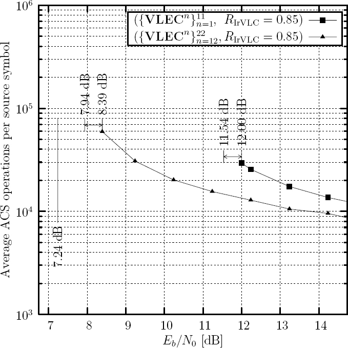
We therefore investigate methods of reducing the complexity associated with IrVLCs in Chapter 9.
As shown in Figures 8.17 and 8.18, the iterative decoding computational complexity required to achieve a BER of 10−5 reduces as the channel’s Eb/N0 value is increased. This is because the EXIT-chart tunnel widens as the Eb/N0 value increases, requiring fewer decoding iterations to reach the top right-hand corner of the EXIT chart. By comparing Figures 8.17 and 8.18, it can be seen that the computational complexity required to achieve aBER of 10−5 at an Eb/N0 value that is a particular distance from the associated Eb/N0 capacity bound is higher for the parameterizations employing a coding rate of RIrVLC = 0.55 compared with those employing a coding rate of RIrVLC = 0.85. For example, the complexity associated with the RIrVLC = 0.55 parameterizations at an Eb/N0 value that is 7 dB above the associated channel’s capacity bound of 7.24 dB is about 75% higher than that associated with the corresponding RIrVLC = 0.85 parameterizations at an Eb/N0 value that is 7 dB above the associated capacity bound of 2.37 dB. This may be explained by the RIrVLC = 0.55 parameterizations’ activation of low-rate component VLEC codebooks that are associated with high computational complexities, as shown in Tables 8.7 and 8.8 as well as Figures 8.7–8.10.
Figure 8.18: Plots of the average number of ACS operations required per source symbol in order to achieve a BER of 10−5 versus Eb/N0 for the IrVLC-URC parameterizations employing a coding rate of RIrVLC = 0.55.

As portrayed in Figure 8.18, the (![]() , RIrVLC = 0.55) arrangement is associated with a 35% higher complexity than that of the (
, RIrVLC = 0.55) arrangement is associated with a 35% higher complexity than that of the (![]() , RIrVLC = 0.55) arrangement, when considering the high channel Eb/N0 value range. As predicted in Section 8.5.2, this may be attributed to the (
, RIrVLC = 0.55) arrangement, when considering the high channel Eb/N0 value range. As predicted in Section 8.5.2, this may be attributed to the (![]() , RIrVLC = 0.55) arrangement’s activation of component VLEC codebooks that were designed to have a low RV-FDM by the GA of Section 8.3, which are associated with low computational complexities, as shown in Table 8.8 as well as Figures 8.8 and 8.10.
, RIrVLC = 0.55) arrangement’s activation of component VLEC codebooks that were designed to have a low RV-FDM by the GA of Section 8.3, which are associated with low computational complexities, as shown in Table 8.8 as well as Figures 8.8 and 8.10.
Similarly, the (![]() , RIrVLC = 0.85) arrangement is associated with a 38% higher complexity at high channel Eb/N0 values than that of the corresponding (
, RIrVLC = 0.85) arrangement is associated with a 38% higher complexity at high channel Eb/N0 values than that of the corresponding (![]() , RIrVLC = 0.85) arrangement, as shown in Figure 8.17. This may be attributed to the activation of low-rate component VLEC codebooks that are associated with a high computational complexity in the (
, RIrVLC = 0.85) arrangement, as shown in Figure 8.17. This may be attributed to the activation of low-rate component VLEC codebooks that are associated with a high computational complexity in the (![]() , RIrVLC = 0.85) arrangement, as shown in Table 8.7 as well as Figures 8.7 and 8.9. We may therefore identify the (
, RIrVLC = 0.85) arrangement, as shown in Table 8.7 as well as Figures 8.7 and 8.9. We may therefore identify the (![]() , RIrVLC = 0.85) arrangement as our preferred parameterization owing to its relatively low computational complexity and the near-capacity operation that it facilitates.
, RIrVLC = 0.85) arrangement as our preferred parameterization owing to its relatively low computational complexity and the near-capacity operation that it facilitates.
8.7 Summary and Conclusions
In this chapter we have proposed the novel RV-FDM of Equation (8.8) as an alternative to the IV-FD lower bound of Equation (8.5) for the characterization of the error-correction capability that is associated with VLEC codebooks. Unlike the IV-FD lower bound, the RVFDM exists within the real domain, allowing the comparison of the error-correction capability of two VLEC codebooks having equal IV-FD lower bounds. Furthermore in Figure 8.3 of Section 8.2 we showed that a VLEC codebook’s RV-FDM affects the number of inflection points appearing in the corresponding inverted EXIT function. This complements the property [204] that the area below an inverted VLEC EXIT function equals the corresponding coding rate and the property that a RV-FDM of at least two yields an inverted VLEC EXIT function that reaches the top right-hand corner of the EXIT chart. Hence, we have shown in Figure 8.3 that the shape of an inverted VLEC EXIT function depends on both the corresponding coding rate and the RV-FDM.
This motivated our novel GA design of Section 8.3, which facilitates the design of VLEC codebooks having arbitrary coding rates as well as RV-FDMs and hence inverted EXIT function shapes, while seeking desirable bit entropies and bit-based trellis complexities. This is in contrast to Algorithm 3.3 of Section 3.3, which was employed to design component VLC codebooks in Chapter 7 and is incapable of designing codebooks having arbitrary coding rates and RV-FDMs without imposing a significant level of ‘trial-and-error’-based human interaction. Recall that in Chapter 7 we speculated that our ability to match the inverted EXIT function of an IrVLC to the EXIT function of a serially concatenated inner codec depends on how much variety is exhibited within the shape of the inverted EXIT functions of the component VLEC codebooks. For this reason, our GA may be considered to be more suitable for the design of IrVLC component codebooks than is Algorithm 3.3 of Section 3.3.
This was investigated in Section 8.5 by employing both our novel GA and Algorithm 3.3 of Section 3.3 to design suites of N = 11 component VLEC codebooks. The suite of component VLEC codebooks designed in Section 8.5.1 by our novel GA had a wide variety of inverted EXIT functions. This was achieved by seeking component VLEC codebooks having a wide variety of coding rates and RV-FDMs. In some cases, high RV-FDMs were sought, resulting in inverted EXIT functions having up to two points of inflection, whilst low RV-FDMs were sought for the remaining component VLEC codebooks, which were associated with inverted EXIT functions having no more than one point of inflection. In order to facilitate a fair comparison, trial and error was not employed when Algorithm 3.3 of Section 3.3 was used to design component VLEC codebooks. Instead, each component VLEC codebook was designed to have a different IV-FD lower bound. As a result, however, the suite of component VLEC codebooks had only a limited variety of coding rates and RV-FDMs, resulting in the limited variety of inverted EXIT functions shown in Figure 8.7.
The suitability of the component VLEC codebook suites for use in IrVLCs was investigated by employing the algorithm of [149] to match the corresponding inverted IrVLC EXIT functions to a selection of inner codec EXIT functions. These were provided by the serially concatenated URC codec of Figure 8.6, employing BPSK modulation for transmission over an uncorrelated narrowband Rayleigh fading channel having a range of Eb/N0 values. As predicted by the EXIT chart’s area property of [204], the areas beneath the URC EXIT functions were found to be equal to the corresponding channel capacities, showing that the amalgamation of URCs and BPSK modulation does not suffer from the effective throughput loss of Chapter 7’s TCM inner codec.
The suite of component VLEC codebooks designed by our novel GA in Section 8.5.1 was found to be more suitable for use in IrVLCs than that designed using Algorithm 3.3 of Section 3.3. More specifically, an open IrVLC-URC EXIT-chart tunnel was found to be achievable in Figure 8.12 at channel Eb/N0 values within 1 dB of the Rayleigh fading channel’s capacity bound for a wide range of effective throughputs, when employing the suite of component VLEC codebooks generated using our GA. By contrast, open EXIT-chart tunnels could only be achieved when employing the suite designed by Algorithm 3.3 of Section 3.3 for a limited range of effective throughputs and within a significantly higher margin of 4.4 dB from the Eb/N0 capacity bound, as seen in Figure 8.12. This confirms the speculation that our ability to perform EXIT-chart matching depends on how much variety is exhibited within the suite of inverted EXIT functions.
However, regardless of the component VLEC codebook suite employed, the high starting point of the URC’s EXIT function along the EXIT chart’s Iei axis in Figure 8.13 was found to limit the EXIT-chart matching accuracy. This is because the inverted IrVLC EXIT function always emerges from the (0, 0) point of the EXIT chart. Hence, in Chapter 9 we investigate the employment of Irregular Unity-Rate Codes (IrURCs), having composite EXIT functions that may be shaped so that they start from a point along the EXIT chart’s Iei axis that is closer to the (0, 0) point. In this way, the IrVLC and IrURC EXIT functions will be jointly matched to each other, creating an EXIT-chart tunnel that is narrow along its entire length and facilitating operation at Eb/N0 values that are even closer to the channel’s capacity bound.
It was found in Figure 8.12 that lower IrVLC coding rates facilitated improved EXIT-chart matching, yielding open EXIT-chart tunnels for Eb/N0 values in excess of thresholds that are closer to the channel’s capacity bound. For our IrVLC-URC parameterizations outlined in Table 8.8 and employing the suite of component VLEC codebooks designed using our novel GA, an open EXIT-chart tunnel was achieved in Figure 8.12 within 0.7 dB of the Eb/N0 capacity bound when employing a coding rate of RIrVLC = 0.85. An even lower discrepancy of 0.42 dB was seen in Figure 8.12 for a coding rate of RIrVLC = 0.55. Note that the effective EXIT-chart matching of the latter case was attributed to its activation of component VLEC codebooks having low RV-FDMs, which were shown in Figure 8.8 to have inverted EXIT functions exhibiting no more than one point of inflection. In the case of parameterizations employing the suite of component VLEC codebooks outlined in Table 8.7 and designed using Algorithm 3.3 of Section 3.3, an open EXIT-chart tunnel was created in Figure 8.12 within 4.3 dB of the Eb/N0 capacity bound for a coding rate of RIrVLC = 0.85 and with in 1 dB for a coding rate of RIrVLC = 0.55.
However, we observed a discrepancy in Figures 8.15–8.18 between the Eb/N0 value at which a BER of 10−5 could be achieved and that at which an open EXIT-chart tunnel was achieved. This may be explained by the APP SISO IrVLC decoder’s sensitivity to residual correlation within the a priori LLR frame that was not entirely eliminated by the interleaver having a length of 100 000 bits. As a result, the match between the iterative decoding trajectory and the inner and outer EXIT functions was poor, requiring the widening of the EXIT-chart tunnel in order for the trajectory to reach the top right-hand corner of the EXIT chart. As speculated in Section 7.4.3, the APP SISO IrVLC decoder’s sensitivity to this extrinsic information correlation was found to increase as the IrVLC coding rate was reduced. Indeed, a discrepancy of about 0.45 dB was observed in Figures 8.15 and 8.17 for our IrVLC-URC parameterizations employing a coding rate of RIrVLC = 0.85, which compared favorably with the discrepancies of 0.58 dB and 0.99 dB observed in Figures 8.16 and 8.18 for the RIrVLC = 0.55 parameterizations.
Whilst the most accurate EXIT-chart matching was achieved in Figure 8.13d by the RIrVLC = 0.55 IrVLC-URC parameterization employing the suite of component VLEC codebooks designed using our novel GA of Section 8.3, it did not offer the nearest-capacity operation. More specifically, this parameterization could only achieve a BER of less than 10−5 for Eb/N0 values in excess of a limit within 1.41 dB of the channel’s Eb/N0 capacity bound, owing to its sensitivity to correlation within the a priori LLR frame, as described above. By contrast, the equivalent parameterization having a coding rate of RIrVLC = 0.85 suffered the least sensitivity to this correlation and therefore achieved a BER of less than 10−5 for Eb/N0 values in excess of a limit that was within a smaller discrepancy of 1.15 dB from the channel’s capacity bound.
Furthermore, the iterative decoding computational complexity required to achieve a BER of 10−5 at a particular distance from the channel’s Eb/N0 capacity bound was found to decrease as the coding rate was increased. Indeed, observe in Figure 8.17 for the RIrVLC = 0.55 parameterizations, that the complexity associated with an Eb/N0 value that is 7 dB above the associated channel’s capacity bound was found to be about 75% higher than that of the RIrVLC = 0.85 parameterizations. Note that the relatively low complexity of the RIrVLC = 0.55 parameterization employing the suite of component VLEC codebooks designed using our novel GA was attributed to its activation of component VLEC codebooks having low RV-FDMs, which were shown to be associated with low complexities in Figures 8.8 and 8.10. Owing to its near-capacity operation and low computational complexity, the RIrVLC = 0.85 parameterization employing the suite of component VLEC codebooks designed using our novel GA and summarized in Table 8.8 was identified as our preferred arrangement.
In each IrVLC-URC parameterization considered, the IrVLC’s MAP sequence estimator’s BER performance was found to be dominated by that of a single activated component VLEC codebook. In each case, this particular component VLEC codebook encoded a significant fraction of the source symbols and had a low RV-FDM, which was found to be associated with a relatively poor BER performance in Figures 8.9 and 8.10. As a result, the particular component VLEC codebook was responsible for a high number of bit errors, which eclipsed or dominated those of any other activated codebook. However, we concluded that we may justify the computational complexity required to continue iterative decoding until convergence to an infinitesimally low BER is achieved.
Finally, we demonstrated in Section 8.5.5 that the amount of side information required to facilitate the IrVLC decoding can be reduced to less than 0.35% of the transmitted information, by employing only a single sub-frame per component VLEC codebook. This compares favorably with the 4% of the transmitted information that was required by the IrVLC-TCM schemes of Chapter 7, owing to their employment of multiple transmission sub-frames per component codebook.