Chapter 7
Irregular Variable-Length Codes for EXIT-Chart Matching1
7.1 Introduction
As demonstrated in Section 6.6, a serially concatenated [275] transmission scheme is capable of achieving iterative decoding [278] convergence to an infinitesimally low probability of error at near-capacity Signal-to-Noise Ratios (SNRs), if the EXtrinsic Information Transfer (EXIT) functions of the inner and outer codecs are well matched. This motivated the design of Irregular Convolutional Code (IrCC) schemes in [149], as described in Section 5.5.
The inverted EXIT function of an outer IrCC channel codec can be specifically shaped in order to match the EXIT function of a serially concatenated inner codec. This is possible because IrCCs amalgamate a number of component Convolutional Codes (CC) [140] having different coding rates, each of which is employed to generate a specific fraction of the IrCCencoded bit stream. As described in Section 5.5, the composite inverted IrCC EXIT function is given as a weighted average of the inverted EXIT functions of the individual component CCs, where each weight is given by the particular fraction of the IrCC-encoded bit stream that is generated by the corresponding component CC. Hence, it is the specific selection of these fractions that facilitates the shaping of the inverted composite IrCC EXIT function. Using the EXIT-chart matching algorithm of [149], the inverted IrCC EXIT chart may be matched to the EXIT function of the inner codec in this way. This facilitates the creation of an open EXIT-chart tunnel [267] at low channel SNRs that approach the channel’s capacity bound.
However, the constituent bit-based CCs [140] of the IrCC codec of [149] are unable to exploit the unequal source symbol occurrence probabilities that are typically associated with audio, speech, image and video sources [151, 152]. Note that unequal source symbol occurrence probabilities were exemplified in Section 6.3.2. Since the exploitation of all available redundancy is required for near-capacity operation [133], the Huffman source encoder [155] of Chapter 2 must be employed to remove this source redundancy before IrCC encoding commences. However, the reconstruction of the Huffman-encoded bits with a particularly low Bit-Error Ratio (BER) is required in order that Huffman decoding [155] can achieve a low Symbol-Error Ratio (SER), owing to its high error sensitivity, which often leads to loss of synchronization.
1Part of this chapter is based on [202] © IEEE (2009).
This motivates the application of the Variable-Length Error-Correction (VLEC) code [179] and Reversible Variable-Length Code (RVLC) [276] classes of Variable-Length Codes (VLCs) as an alternative to the concatenated Huffman and CC coding of sequences of source symbols having values with unequal probabilities of occurrence. Unlike CCs, these joint source and channel coding VLC schemes are capable of exploiting unequal source symbol occurrence probabilities, as described in Chapter 3. More specifically, source symbols having indices of k ![]() [1 ... K] and associated with unequal probabilities of occurrence
[1 ... K] and associated with unequal probabilities of occurrence ![]() are mapped to binary codewords of varying lengths
are mapped to binary codewords of varying lengths ![]() from a K -entry codebook VLC during VLC encoding. Typically, the more frequently a particular source symbol value occurs, the shorter its VLC codeword, resulting in a reduced average codeword length of
from a K -entry codebook VLC during VLC encoding. Typically, the more frequently a particular source symbol value occurs, the shorter its VLC codeword, resulting in a reduced average codeword length of

In order that each valid VLC codeword sequence may be uniquely decoded, a lower bound equal to the source entropy of

is imposed upon the average codeword length L(VLC). Any discrepancy between L(VLC) and E is quantified by the coding rate of

and may be attributed to the intentional introduction of redundancy into the VLEC or RVLC codewords. Naturally, this intentionally introduced redundancy imposes code constraints that limit the set of legitimate sequences of VLC-encoded bits. Like the code constraints of CCs [140], the VLC code constraints may be exploited in order to provide an error-correcting capability during VLC decoding [179]. Note that the lower the VLC coding rate, the higher the associated potential error correction capability, as described in Chapter 3. Furthermore, unlike in CC decoding, any redundancy owing to the unequal occurrence probabilities of the source symbol values may also be exploited during VLC decoding [179].
Depending on the coding rate R(VLC) of the VLECs or RVLCs, the associated code constraints render their decoding substantially less sensitive to bit errors than Huffman decoding is, as described in Chapter 3. Hence, a coding gain of 1 dB at a SER of 10−5 has been observed by employing VLEC coding having a particular coding rate instead of a concatenated Huffman and Bose–Chaudhuri–Hocquenghem (BCH) [302, 303] coding scheme having the same coding rate [179].
Hence the application of EXIT-chart matching invoking Irregular Variable-Length Codes (IrVLCs) is motivated for the sake of near-capacity joint source and channel coding of source symbol sequences having values exhibiting unequal occurrence probabilities. In this chapter we therefore employ a novel IrVLC scheme as our outer source codec, which we serially concatenate [275, 278] with an inner channel codec for the sake of exchanging extrinsic information. As shown in Figure 7.1, instead of the component CCs employed in IrCC schemes, the proposed IrVLC scheme employs component VLC codebooks. These have different coding rates and are used for encoding appropriately selected fractions of the input source symbol stream. In this way the resultant composite inverted EXIT function may be shaped in order to ensure that it does not cross the EXIT function of the inner channel codec.
Figure 7.1: Conventional irregular coding design process. This chapter presents modifications to the aspects of this process that are indicated using a bold box.

Note that the proposed scheme has an Unequal Error Protection (UEP) capability [304], since different fractions of the input source symbol stream are protected by different VLC codebooks having different coding rates and, hence, different error-correction capabilities. In a manner similar to that of [189–191], for example, this UEP capability may be employed to appropriately protect audio-, speech-, image-and video-encoded bit sequences, which are typically generated using diverse encoding techniques and exhibit various error sensitivities. For example, video coding typically achieves compression by employing Motion Compensation (MC) [154] to exploit the characteristic inter-frame redundancy of video information and the Discrete Cosine Transform (DCT) [153] to exploit the intra-frame redundancy, as described in Section 6.1. As noted in [151], typically a higher degree of video reconstruction distortion results from transmission errors that affect the MC-generated motion vectors than from those inflicted on the DCT-encoded information. Hence, the proposed scheme’s UEP capability may be employed to protect the MC-encoded information with a relatively strong error-correction capability, whilst employing a relatively weak error-correction code to protect the DCT-encoded information. This approach may hence be expected to yield a lower degree of video reconstruction distortion than would equal protection, as noted in [189–191], for example.
The rest of this chapter is outlined as follows. In Section 7.2 we propose iteratively decoded schemes, in which we opt for serially concatenating IrVLC with Trellis-Coded Modulation (TCM) [277]. Furthermore, Section 7.2 additionally introduces our benchmark schemes, where IrVLC is replaced by regular VLCs having the same coding rate. The design and EXIT-chart-aided characterization of these schemes is detailed in Section 7.3. In Section 7.4 we quantify the attainable performance improvements offered by the proposed IrVLC arrangements compared with that of the regular VLC benchmark schemes. Furthermore, in Section 7.4 we additionally consider a Huffman coding and IrCC-based benchmark. Section 7.4 also employs a novel method of quantifying the computational complexity required for the schemes considered in order to achieve different source sample reconstruction qualities at a range of Rayleigh fading channel SNRs. This method is employed to select our preferred scheme and to characterize the benefits of UEP. Finally, we offer our conclusions in Section 7.5.
7.2 Overview of Proposed Schemes
In this section we provide an overview of a number of serially concatenated [275] and iteratively decoded [278] joint source and channel coding schemes. Whilst the novel schemes introduced in this chapter may be tailored for operating in conjunction with any inner channel codec, we opt for employing TCM [277] in each of our considered schemes. This provides error protection without any bandwidth expansion or effective bit-rate reduction by accommodating the additional redundancy by transmitting more bits per channel symbol. The choice of TCM is further justified, since A Posteriori Probability (APP) TCM Soft-Input Soft-Output (SISO) decoding, similarly to APP SISO IrVLC decoding, operates on the basis of Add, Compare and Select (ACS) operations within a trellis structure. Hence, the APP SISO IrVLC and TCM decoders can share resources in systolic-array-based chips, facilitating a cost-effective implementation. Furthermore, we will show that TCM exhibits attractive EXIT characteristics in the proposed IrVLC context even without requiring Turbo Trellis-Coded Modulation (TTCM)- or Bit-Interleaved Coded Modulation (BICM)-style internal iterative decoding [296].
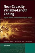
Our considered schemes differ in their choice of the outer source codec. Specifically, we consider a novel IrVLC codec and an equivalent regular VLC-based benchmark in this role. In both cases we employ both Symbol-Based (SB) [181] and Bit-Based (BB) [180] VLC decoding, resulting in a total of four different configurations. We refer to these four schemes as the SBIrVLC-, BBIrVLC-, SBVLC-and BBVLC-TCM arrangements, as appropriate. A schematic that is common to each of these four considered schemes is provided in Figure 7.2.
7.2.1 Joint Source and Channel Coding
The schemes considered are designed for facilitating the near-capacity detection of source samples received over an uncorrelated narrowband Rayleigh fading channel. We consider the case of independent identically distributed (i.i.d.) source samples, which may represent the prediction residual error that remains following the predictive coding of audio, speech, image or video information [151, 152], for example. Note that this was exemplified in the novel video codec of Chapter 6, in which frame differencing was employed, as depicted in Figure 6.1. A Gaussian source sample distribution is assumed here, since this has widespread applications owing to the wide applicability of the central limit theorem [305]. Additionally, a zero mean and unity source sample variance was assumed, resulting in the Probability Density Function (PDF) shown in Figure 7.3. Note however that, with the aid of suitable adaptation, the techniques proposed in this chapter may be just as readily applied to arbitrary source sample distributions.
In the block Q of the transmitter depicted in Figure 7.2, each real-valued source sample of the source sample frame e is quantized [164,165]to one of the K = 16 quantization levels ![]() provided in Figure 7.3. In each case, the selected quantization level is that which represents the source sample with the minimum squared error. Figure 7.3 provides decision boundaries, which are located halfway between each adjacent pair of quantization levels. Each pair of adjacent decision boundaries specifies the range of source sample values that are quantized to the quantization level at the center of gravity of this interval, resulting in the minimum squared error. Following quantization, each source sample in the source sample frame e is represented by a symbol in the source symbol frame s that represents the index of the selected quantization level êk and has a value of k
provided in Figure 7.3. In each case, the selected quantization level is that which represents the source sample with the minimum squared error. Figure 7.3 provides decision boundaries, which are located halfway between each adjacent pair of quantization levels. Each pair of adjacent decision boundaries specifies the range of source sample values that are quantized to the quantization level at the center of gravity of this interval, resulting in the minimum squared error. Following quantization, each source sample in the source sample frame e is represented by a symbol in the source symbol frame s that represents the index of the selected quantization level êk and has a value of k ![]() [1 ... K].
[1 ... K].
Figure 7.2: Schematic of the SBIrVLC-, BBIrVLC-, SBVLC-and BBVLC-TCM schemes. In the IrVLC schemes, the M VLC encoders, APP SISO decoders and MAP sequence estimators are each based upon one of N component VLC codebooks. By contrast, in the VLC benchmarks, all of the M VLC encoders, decoders and sequence estimators are based upon the same VLC codebook.©IEEE [196] Maunder et al. 2008.
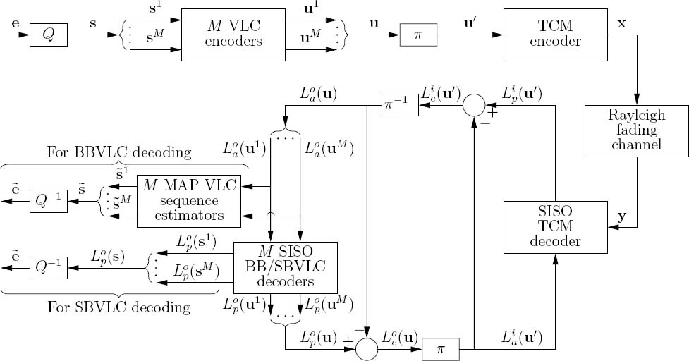
Owing to the lossy nature of quantization, distortion is imposed upon the reconstructed source sample frame ê that is obtained following inverse quantization in the block, as described in Section 3.2. Note that the set of quantization levels depicted in Figure 7.3 represents those of Lloyd–Max quantization [164, 165]. This employs the K-means algorithm [233] to search for the set of quantization levels that minimizes the expected quantization distortion. In the case of the quantization levels seen in Figure 7.3, the expected Signal-to-Quantization-Noise Ratio (SQNR) is about 20 dB. Note however that, again, with the aid of suitable adaptation, the techniques advocated in this chapter may be just as readily applied to arbitrary quantizers.
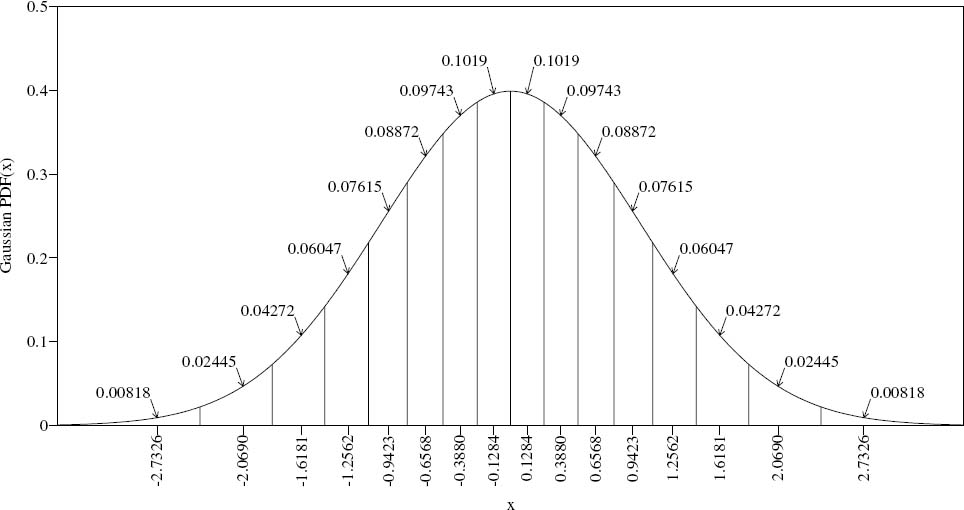
Also note that Lloyd–Max quantization results in a large variation in the occurrence probabilities of the resultant source symbol values. These occurrence probabilities are given by integrating the source PDF between each pair of adjacent decision boundaries, resulting in the values provided in Figure 7.3. These source symbol values’ occurrence probabilities ![]() are repeated in Table 7.1 and can be seen to vary by more than an order of magnitude. These probabilities correspond to the varying source symbol informations
are repeated in Table 7.1 and can be seen to vary by more than an order of magnitude. These probabilities correspond to the varying source symbol informations ![]() provided in Table 7.1, motivating the application of VLC and giving a source entropy of E = 3.77 bits per source symbol, according to Equation (7.2).
provided in Table 7.1, motivating the application of VLC and giving a source entropy of E = 3.77 bits per source symbol, according to Equation (7.2).
Figure 7.3: Gaussian PDF for unity mean and variance. The x-axis is labeled with the K = 16 Lloyd–Max quantization levels ![]() as provided in [164]. The decision boundaries are employed to decompose the Gaussian PDF into K = 16 sections. The integral of the PDF between each pair of adjacent decision boundaries is provided.
as provided in [164]. The decision boundaries are employed to decompose the Gaussian PDF into K = 16 sections. The integral of the PDF between each pair of adjacent decision boundaries is provided.
In the transmitter of the proposed scheme, the Lloyd–Max quantized source symbol frame s is decomposed into M = 300 sub-frames ![]() as shown in Figure 7.2. In the case of the SBIrVLC-and SBVLC-TCM schemes, this decomposition is necessary for the sake of limiting the computational complexity of VLC decoding, since the number of transitions in the symbol-based VLC trellis is inversely proportional to the number of sub-frames in this case [181], as described in Section 3.4.1. We opt for employing the same decomposition of the source symbol frames into sub-frames in the case of the BBIrVLC- and BBVLC-TCM schemes for the sake of ensuring that we make a fair comparison with the SBIrVLC-and SBVLC-TCM schemes. This is justified, since the decomposition considered benefits the performance of the BBIrVLC-and BBVLC-TCM schemes, as will be detailed below. Each source symbol sub-frame sm comprises J = 100 source symbols. Hence, the total number of source symbols in a source symbol frame becomes M · J = 30 000. As described above, each Lloyd–Max quantized source symbol in the sub-frame sm has a K-ary value
as shown in Figure 7.2. In the case of the SBIrVLC-and SBVLC-TCM schemes, this decomposition is necessary for the sake of limiting the computational complexity of VLC decoding, since the number of transitions in the symbol-based VLC trellis is inversely proportional to the number of sub-frames in this case [181], as described in Section 3.4.1. We opt for employing the same decomposition of the source symbol frames into sub-frames in the case of the BBIrVLC- and BBVLC-TCM schemes for the sake of ensuring that we make a fair comparison with the SBIrVLC-and SBVLC-TCM schemes. This is justified, since the decomposition considered benefits the performance of the BBIrVLC-and BBVLC-TCM schemes, as will be detailed below. Each source symbol sub-frame sm comprises J = 100 source symbols. Hence, the total number of source symbols in a source symbol frame becomes M · J = 30 000. As described above, each Lloyd–Max quantized source symbol in the sub-frame sm has a K-ary value ![]() where we have j
where we have j ![]() [1 ...J].
[1 ...J].
As described in Section 7.1, we employ N component VLC codebooks to encode the source symbols, where we opted for N = 15 for the SBIrVLC and BBIrVLC schemes and N = 1 for the regular SBVLC and BBVLC schemes. Each Lloyd–Max quantized source symbol sub-frame sm is VLC-encoded using a single component VLC codebook VLCn, where we have n ![]() [1 ...N]. In the case of the SBIrVLC and BBIrVLC schemes, the particular fraction Cn of the set of source symbol sub-frames that is encoded by the specific component VLC codebook VLCn is fixed and will be derived in Section 7.3. The specific Lloyd–Max quantized source symbols having the value of k
[1 ...N]. In the case of the SBIrVLC and BBIrVLC schemes, the particular fraction Cn of the set of source symbol sub-frames that is encoded by the specific component VLC codebook VLCn is fixed and will be derived in Section 7.3. The specific Lloyd–Max quantized source symbols having the value of k ![]() [1 ...K] and encoded by the specific component VLC codebook VLCn are represented by the codeword VLCn,k, which has a length of In,k bits. The J = 100 VLC codewords that represent the J = 100 Lloyd–Max quantized source symbols in each source symbol sub-frame sm are concatenated to provide the transmission sub-frame
[1 ...K] and encoded by the specific component VLC codebook VLCn are represented by the codeword VLCn,k, which has a length of In,k bits. The J = 100 VLC codewords that represent the J = 100 Lloyd–Max quantized source symbols in each source symbol sub-frame sm are concatenated to provide the transmission sub-frame
TABLE 7.1: The probabilities of occurrence P(k) and informations − log2(P(k)) of the K = 16 source symbol values k ![]() [1 ... K] that result from the Lloyd–Max quantization of Gaussian distributed source samples (the corresponding source symbol entropy is E = 3.77 bits per source symbol, according to Equation (7.2))
[1 ... K] that result from the Lloyd–Max quantization of Gaussian distributed source samples (the corresponding source symbol entropy is E = 3.77 bits per source symbol, according to Equation (7.2))
† Also provided is the composition of the K = 16 codewords in the corresponding Huffman codebook Huff = ![]() [155], having the codeword lengths
[155], having the codeword lengths ![]() According to Equation (7.1), the average Huffman codeword length is L(Huff) = 3.81 bits per source symbol, which corresponds to a Huffman coding rate of RHuff = 0.99, according to Equation (7.3).
According to Equation (7.1), the average Huffman codeword length is L(Huff) = 3.81 bits per source symbol, which corresponds to a Huffman coding rate of RHuff = 0.99, according to Equation (7.3).
![]()
Owing to the variable lengths of the VLC codewords, each of the M = 300 transmission sub-frames typically consists of a different number of bits. In order to facilitate the VLC decoding of each transmission sub-frame um, it is necessary to explicitly convey its length to the receiver. Furthermore, this highly error-sensitive side information must be reliably protected against transmission errors. This may be achieved using a low rate block code, for example. For the sake of avoiding obfuscation, this is not shown in Figure 7.2. Note that the choice of the specific number of sub-frames M in each frame constitutes a trade-off between the computational complexity of SBVLC decoding or the performance of BBVLC decoding and the amount of side information that must be conveyed. In Section 7.3 we comment on the amount of side information that is required for reliably conveying the specific number of bits in each transmission sub-frame to the decoder.

In the scheme’s transmitter, the M = 300 number of transmission sub-frames ![]() are concatenated. As shown in Figure 7.2, the resultant transmission frame u has a length of
are concatenated. As shown in Figure 7.2, the resultant transmission frame u has a length of ![]() bits.
bits.
In the proposed scheme, the VLC codec is protected by a serially concatenated TCM codec. Following VLC encoding, the bits of the transmission frame u are interleaved using the function π in order to provide the interleaved transmission frame u′, which is TCM encoded in order to obtain the channel’s input symbols x, as shown in Figure 7.2. These are transmitted over an uncorrelated narrowband Rayleigh fading channel and are received as the channel’s output symbols y, as seen in Figure 7.2.
7.2.2 Iterative Decoding
In the receiver, APP SISO TCM and VLC decoding are performed iteratively, as shown in Figure 7.2. Both of these decoders invoke the Bahl–Cocke–Jelinek–Raviv (BCJR) algorithm [48] on the basis of their trellises. Symbol-based trellises are employed in the case of TCM [277], SBIrVLC and SBVLC [181] decoding, whilst BBIrVLC and BBVLC decoding rely on bit-based trellises [180]. All BCJR calculations are performed in the logarithmic probability domain and using an eight-entry lookup table for correcting the Jacobian approximation in the Log-MAP algorithm [296]. The proposed approach requires only Add, Compare and Select (ACS) computational operations during iterative decoding, which will be used as our complexity measure, since it is characteristic of the complexity/area/speed trade-offs in systolic-array-based chips.
As usual, extrinsic soft information, represented in the form of Logarithmic Likelihood Ratios (LLRs) [292], is iteratively exchanged between the TCM and VLC decoding stages for the sake of assisting each other’s operation [275, 278], as described in Section 4.1. In Figure 7.2, L(·) denotes the LLRs of the bits concerned (or the log-APPs of the specific symbols as appropriate), where the superscript i indicates inner TCM decoding, while o corresponds to outer VLC decoding. Additionally, a subscript denotes the dedicated role of the LLRs (or log-APPs), with a, p and e indicating a priori, a posteriori and extrinsic information respectively.
During each decoding iteration, the inner TCM decoder is provided with a priori LLRs pertaining to the interleaved transmission frame ![]() , as shown in Figure 7.2. These LLRs are obtained from the most recent operation of the outer VLC decoding stage, as will be highlighted below. In the case of the first decoding iteration, no previous VLC decoding has been performed and hence the a priori LLRs Lia(u′) provided for TCM decoding are all zero-valued, corresponding to a probability of 0.5 for both ‘0’ and ‘1’. Given the channel’s output symbols y and the a priori LLRs Lia(u′), the BCJR algorithm is employed for obtaining the a posteriori LLRs Lip(u′), as shown in Figure 7.2.
, as shown in Figure 7.2. These LLRs are obtained from the most recent operation of the outer VLC decoding stage, as will be highlighted below. In the case of the first decoding iteration, no previous VLC decoding has been performed and hence the a priori LLRs Lia(u′) provided for TCM decoding are all zero-valued, corresponding to a probability of 0.5 for both ‘0’ and ‘1’. Given the channel’s output symbols y and the a priori LLRs Lia(u′), the BCJR algorithm is employed for obtaining the a posteriori LLRs Lip(u′), as shown in Figure 7.2.
During iterative decoding, it is necessary to prevent the reuse of already exploited information, since this would limit the attainable iteration gain [296], as described in Section 4.2. This is achieved following TCM decoding by the subtraction of Lia(u′) from Lip(u′), as shown in Figure 7.2. The resultant extrinsic LLRs Lie(u′) are de-interleaved in the block π−1 and forwarded as a priori LLRs for VLC decoding. As described in Section 4.1, interleaving is employed in order to mitigate correlation within the a priori LLR frames. This is necessary since the BCJR algorithm assumes that all a priori LLRs that can influence any particular decoding decision are uncorrelated.
Just as M = 300 separate VLC encoding processes are employed in the proposed scheme’s transmitter, M = 300 separate VLC decoding processes are employed in its receiver. In parallel to the composition of the bit-based transmission frame u from its M = 300 sub-frames, the a priori LLRs Loa(u) are decomposed into M = 300 sub-frames, as shown in Figure 7.2. This is achieved with the aid of the explicit side information that conveys the number of bits I m in each transmission sub-frame um. Each of the M = 300 VLC decoding processes is provided with the a priori LLR sub-frame Loa (um) and in response it generates the a posteriori LLR sub-frame Lop (um), m ![]() [1 ...M]. These a posteriori LLR sub-frames are concatenated in order to provide the a posteriori LLR frame Lop(u), as shown in Figure 7.2. Following the subtraction of the a priori LLRs Loa(u), the resultant extrinsic LLRs Loe(u) are interleaved and forwarded as a priori information to the next TCM decoding iteration.
[1 ...M]. These a posteriori LLR sub-frames are concatenated in order to provide the a posteriori LLR frame Lop(u), as shown in Figure 7.2. Following the subtraction of the a priori LLRs Loa(u), the resultant extrinsic LLRs Loe(u) are interleaved and forwarded as a priori information to the next TCM decoding iteration.
In the case of SBIrVLC and SBVLC decoding, each of the M = 300 VLC decoding processes additionally provides log-APPs pertaining to the corresponding source symbol sub-frame Lop (sm). This comprises a set of K number of log-APPs for each source symbol smj in the sub-frame sm, where j ![]() [1 ...J]. Each of these log-APPs provides the logarithmic probability that the corresponding source symbol smj has the particular value k
[1 ...J]. Each of these log-APPs provides the logarithmic probability that the corresponding source symbol smj has the particular value k ![]() [1 ...K]. In the receiver of Figure 7.2, the source symbols’ log-APP sub-frames are concatenated to provide the source symbol log-APP frame Lop (s). By inverse-quantizing this soft information in the block Q−1, we may obtain a frame of Minimum Mean Square Error (MMSE) source sample estimates
[1 ...K]. In the receiver of Figure 7.2, the source symbols’ log-APP sub-frames are concatenated to provide the source symbol log-APP frame Lop (s). By inverse-quantizing this soft information in the block Q−1, we may obtain a frame of Minimum Mean Square Error (MMSE) source sample estimates ![]() , which approximates the reconstructed source sample frame ê described in Section 7.2.1. More specifically, each source sample estimate is obtained by using the corresponding set of K source symbol value probabilities to find the weighted average of the K number of quantization levels
, which approximates the reconstructed source sample frame ê described in Section 7.2.1. More specifically, each source sample estimate is obtained by using the corresponding set of K source symbol value probabilities to find the weighted average of the K number of quantization levels ![]()
Conversely, in the case of BBIrVLC and BBVLC decoding, no symbol-based a posteriori output is available. In this case, each source symbol sub-frame sm is estimated from the corresponding a priori LLR sub-frame Loa (um). This may be achieved by employing Maximum A posteriori Probability (MAP) sequence estimation operating on a bit-based trellis structure, as shown in Figure 7.2. Unlike APP SISO SBIrVLC and SBVLC decoding, bit-based MAP sequence estimation cannot exploit the knowledge that each sub-frame sm comprises J = 100 source symbols. For this reason, the resultant hard decision estimate ![]() m of each source symbol sub-frame sm may or may not contain J = 100 source symbols.
m of each source symbol sub-frame sm may or may not contain J = 100 source symbols.
In order that we may prevent the loss of synchronization that this would imply, source symbol estimates are removed from, or appended to the end of, each source symbol sub-frame estimate ![]() m in order to ensure that they each comprise exactly J = 100 source symbol estimates. Note that it is the decomposition of the source symbol frame s into sub-frames that provides this opportunity to mitigate the loss of synchronization that is associated with bit-based MAP VLC sequence estimation. Hence the decomposition of the source symbol frame s into sub-frames benefits the performance of the BBIrVLC-and BBVLC-TCM schemes, as mentioned above.
m in order to ensure that they each comprise exactly J = 100 source symbol estimates. Note that it is the decomposition of the source symbol frame s into sub-frames that provides this opportunity to mitigate the loss of synchronization that is associated with bit-based MAP VLC sequence estimation. Hence the decomposition of the source symbol frame s into sub-frames benefits the performance of the BBIrVLC-and BBVLC-TCM schemes, as mentioned above.
Following MAP sequence estimation, the adjusted source symbol sub-frame estimates ![]() m are concatenated for the sake of obtaining the source symbol frame estimate
m are concatenated for the sake of obtaining the source symbol frame estimate ![]() . This may be inverse-quantized in order to obtain the source sample frame estimate
. This may be inverse-quantized in order to obtain the source sample frame estimate ![]() . Note that for the reconstruction of a source sample frame estimate
. Note that for the reconstruction of a source sample frame estimate ![]() from a given a priori LLR frame Lao(u), a higher level of source distortion may be expected in the BBIrVLC-and BBVLC-TCM schemes than in the corresponding SBIrVLC-and SBVLC-TCM schemes. This is due to the BBIrVLC-and BBVLC-TCM schemes’ reliance on hard decisions as opposed to the soft decisions of the SBIrVLC-and SBVLC-TCM schemes. However, this reduced performance substantially benefits us in terms of a reduced complexity, since the bit-based VLC decoding trellis employed during APP SISO BBIrVLC and BBVLC decoding and MAP sequence estimation contains significantly fewer transitions than the symbol-based VLC decoding trellis of APP SISO SBIrVLC and SBVLC decoding, as described in Section 3.4.
from a given a priori LLR frame Lao(u), a higher level of source distortion may be expected in the BBIrVLC-and BBVLC-TCM schemes than in the corresponding SBIrVLC-and SBVLC-TCM schemes. This is due to the BBIrVLC-and BBVLC-TCM schemes’ reliance on hard decisions as opposed to the soft decisions of the SBIrVLC-and SBVLC-TCM schemes. However, this reduced performance substantially benefits us in terms of a reduced complexity, since the bit-based VLC decoding trellis employed during APP SISO BBIrVLC and BBVLC decoding and MAP sequence estimation contains significantly fewer transitions than the symbol-based VLC decoding trellis of APP SISO SBIrVLC and SBVLC decoding, as described in Section 3.4.
In the next section we detail the design of our IrVLC scheme and characterize each of the SBIrVLC-, BBIrVLC-, SBVLC-and BBVLC-TCM schemes with the aid of EXIT-chart analysis.
7.3 Parameter Design for the Proposed Schemes
7.3.1 Scheme Hypothesis and Parameters
As described in Section 7.1, the SBIrVLC and BBIrVLC schemes may be constructed by employing a number of component VLC codebooks having different coding rates, each of which encodes an appropriately chosen fraction of the input source symbols. We opted for using N = 15 component VLC codebooks {VLCn}15n=1 that were specifically designed for encoding K = 16-level Lloyd–Max quantized Gaussian i.i.d. source samples. As shown in Figure 7.1, these N = 15 component VLC codebooks were selected from a large number of candidates using a significant amount of ‘trial-and-error’-based human interaction in order to provide a suite of ‘similarly spaced’ EXIT functions. More specifically, the N = 15 component VLC codebooks comprised 13 different Variable-Length Error-Correcting (VLEC) designs having various so-called minimum block, convergence and divergence distances as defined in Section 3.3, complemented by a Symmetric Reversible Variable-Length Coding (SRVLC) and an Asymmetric Reversible Variable-Length Coding (ARVLC) design. These codebooks were designed using Algorithms C and E of Section 3.3.
As described in Section 3.3, the free distance lower bound of a VLC codebook VLCn can be calculated as
![]()
where dbmin(VLCn) is defined as the minimum block distance between any pair of equal-length codewords in the VLC codebook VLCn, whilst ddmin(VLCn) and dcmin(VLCn) are the minimum divergence and convergence distances between any pair of unequal-length codewords, respectively. In all codebooks, a free distance lower bound of ![]() free(VLCn) ≥ 2 was employed, since this supports iterative decoding convergence to an infinitesimally low probability of error [298], as described in Section 4.3. The resultant average VLC codeword lengths were found to range from 3.94 to 12.18 bits/symbol, according to Equation (7.1). When compared with the source symbol entropy of E = 3.77 bits per source symbol, these correspond to coding rates spanning the range of 0.31 to 0.96, according to Equation (7.3). The properties and composition of the N = 15 component VLC codebooks {VLCn}15n= 1 are summarized in Table 7.2.
free(VLCn) ≥ 2 was employed, since this supports iterative decoding convergence to an infinitesimally low probability of error [298], as described in Section 4.3. The resultant average VLC codeword lengths were found to range from 3.94 to 12.18 bits/symbol, according to Equation (7.1). When compared with the source symbol entropy of E = 3.77 bits per source symbol, these correspond to coding rates spanning the range of 0.31 to 0.96, according to Equation (7.3). The properties and composition of the N = 15 component VLC codebooks {VLCn}15n= 1 are summarized in Table 7.2.
As detailed below, our SBIrVLC and BBIrVLC schemes were designed under the constraint that they have an overall coding rate of RIrVLC = 0.52. This value was chosen because it is the coding rate of the VLC codebook VLC10, which we employ in our SBVLC and BBVLC benchmarks using N = 1codebook. This coding rate results in an average interleaver length of M · J · E/RIrVLC = 217500 bits for all the schemes considered. Note that this interleaver length is nearly three times longer than any of those considered in Chapter 6.
Each of the schemes considered employs the same TCM codec, having the Linear Feedback Shift Register (LFSR) schematic of Figure 6.9. As shown in Figure 6.9, the TCM encoder generates a set of four bits to represent each set of three input bits, giving a coding rate of RTCM = 3/4. Three of the four output bits are systematic replications of the three input bits, whilst the fourth output bit is generated with the aid of the LTCM = 6 modulo-2 memory elements. Note that the TCM codec is a recursive component having an infinite impulse response, since feedback is employed in the shift register of Figure 6.9. As a result, the TCM codec supports iterative decoding convergence to an infinitesimally low probability of error [299], as is the case for our component VLC codebooks, as described above. Hence, we may expect the proposed scheme to achieve iterative decoding convergence to an infinitesimally low probability of error, provided that the channel quality is sufficiently high to create an open EXIT-chart tunnel and the iterative decoding trajectory approaches the inner and outer codecs’ EXIT functions sufficiently closely, as discussed in Section 4.3. Furthermore, Figure 6.10 provides the constellation diagram for the MTCM = 16-ary set-partitioned [277] QAM scheme of the TCM codec. This was employed together with In-phase Quadrature-phase (IQ)-interleaving [293] for transmission over an uncorrelated narrowband Rayleigh fading channel.
Ignoring the modest bit-rate contribution of conveying the side information, the effective throughput of the schemes considered is η =RIrVLC · RTCM · log2(MTCM) = 1.56 bits per channel use. This implies that iterative decoding convergence to an infinitesimally low probability of error cannot be achieved when channel capacities of less than 1.56 bits per channel use [133] are attained at low Ec/N0 values, where Ec is the transmit energy per Rayleigh fading channel use and N0 is the average noise energy. Note that the uncorrelated narrowband Rayleigh fading channel’s capacity for 16QAM is less than 1.56 bits per channel use for Eb/N0 values below 2.6 dB [300], where Eb =Ec/η is the transmit energy per bit of source entropy. Given this point on the corresponding channel capacity versus Eb/N0 function, we will be able to quantify how closely the proposed schemes may approach this ultimate limit.
Table 7.2: Properties and composition of the 15 component VLC codebooks {VLCn}15n= 1
| VLCn | Properties† | Composition‡ |
| VLC1 | (VLEC,2,1,1,2,0.96) | 6,6,5,5,4,4,3,3,3,3,4,4,5,5,6,6, 857E1FD3074A55133A |
| VLC2 | (ARVLC,2,1,1,2,0.91) | 6,6,5,5,4,4,4,3,3,4,4,4,5,5,6,6, 1EB624C9A1D58F6E4A1 |
| VLC3 | (SRVLC,2,1,1,2,0.86) | 7,6,6,5,5,4,4,3,3,4,4,5,5,6,6,7, 7D9C248FCAAC0EDBC641 |
| VLC4 | (VLEC,3,1,1,2,0.81) | 8,7,7,6,6,5,4,2,3,3,4,5,6,7,7,8, 81F6F9E86322ACEDE0E77E |
| VLC5 | (VLEC,4,1,1,2,0.75) | 8,8,7,6,6,5,4,2,3,4,5,6,7,7,8,8, 36EF61EB5BA44D179F5D7E81 |
| VLC6 | (VLEC,2,2,1,2,0.70) | 8,7,7,6,6,6,4,4,4,4,6,6,6,7,7,8, E6C99FCADB9035628FF0E2EA |
| VLC7 | (VLEC,3,2,1,3,0.64) | 8,8,7,7,6,6,6,4,5,5,6,6,7,7,7,9, 7FDE5CD3E65403625A267AAD7C |
| VLC8 | (VLEC,3,2,2,3,0.60) | 9,8,8,7,7,6,6,4,6,6,6,6,7,8,8,9, 696F594FCBA5A03159B3F8B35583 |
| VLC9 | (VLEC,5,2,2,4,0.57) | 10,10,9,8,8,7,6,4,5,5,6,7,8,9,9,10, 126307A57CE367501B2AAC9A69CF9ED |
| VLC10 | (VLEC,4,3,2,4,0.52) | 11,10,9,8,8,7,7,6,6,6,7,7,8,9,9,11, 1673E8F0CB2DAAA401F9CC68CD55E37BF |
| VLC11 | (VLEC,4,3,3,4,0.47) | 11,11,10,9,9,8,7,6,6,7,8,8,9,10,10,12, 11FA38AB9536B72B800F4D67B3355A655663 |
| VLC12 | (VLEC,7,3,3,6,0.43) | 12,12,11,10,10,9,8,6,7,7,8,9,11,11,12,13, 2F696B8EC5D38F93A5007715A363233BBA2B899 |
| VLC13 | (VLEC,5,4,3,5,0.39) | 13,12,11,10,10,9,9,8,9,9,9,10,10,11,11,14, 17455A1FFED72B7CC9380079C479A5F32C9555A A4D |
| VLC14 | (VLEC,9,4,4,8,0.35) | 15,14,14,12,12,11,10,8,9,9,10,11,13,13,14,15, 18DA499F59CAB71C9B55C9C003DE1361552D2CD 7ACFB4D3B |
| VLC15 | (VLEC,8,5,5,8,0.31) | 16,15,15,13,13,12,12,10,10,11,12,12,14,14,15,16, 31D97570AE9A5A9C6A59664D4003FE87CE53537 C671CE53464F3A |
† The properties of each component VLC codebook VLCn are provided using the format (Type, dbmin(VLCn), ddmin(VLCn), dcmin(VLCn), ![]() free(VLCn), R(VLCn)).
free(VLCn), R(VLCn)).
‡ The composition of each component VLC codebook VLCn is specified by providing the K = 16 codeword lengths {In,k}Kk= 1, together with the hexadecimal representation of the ordered concatenation of the K = 16 VLC codewords in the codebook.
Recall from Section 7.2 that it is necessary to convey the length of each transmission sub-frame um to the receiver in order to facilitate its VLC decoding. The amount of side information required may be determined by considering the range of transmission sub-frame lengths that can result from VLC encoding using each of the N = 15 component codebooks. When all J = 100 source symbols in a particular source symbol sub-frame sm are represented by the codeword from the component VLC codebook VLCn having the maximal length max k![]() [1...K] In,k, a maximal transmission sub-frame length of
[1...K] In,k, a maximal transmission sub-frame length of
![]()
results. Similarly, a minimal transmission sub-frame length of
![]()
results, when all source symbols are represented by the minimal-length VLC codeword. A transmission sub-frame um encoded using the component VLC codebook VLCn will therefore have one of (Inmax − Inmin + 1) number of lengths in the range Im ![]() [Inmin...Inmax Hence, the length of the transmission sub-frame Im can be represented using a fixed-length codeword comprising
[Inmin...Inmax Hence, the length of the transmission sub-frame Im can be represented using a fixed-length codeword comprising ![]() number of bits. When considering the VLC max min codeword lengths provided in Table 7.2, it was found for all schemes that a single 10-bit fixed-length codeword of side information is sufficient for conveying the length of each of the M = 300 transmission sub-frames umin each transmission frame u. As suggested in Section 7.2, this error-sensitive side information may be protected by a low-rate block code in order to ensure its reliable transmission. Using a Rrep = 1/3-rate repetition code results in a total of 10 · M/Rrep = 9 000 bits of side information per frame, which represents an average of just 4% of the transmitted information, when appended to the transmission frame u, which has an average length of M · J · E/RIrVLC = 217 500 bits for all of the schemes considered.
number of bits. When considering the VLC max min codeword lengths provided in Table 7.2, it was found for all schemes that a single 10-bit fixed-length codeword of side information is sufficient for conveying the length of each of the M = 300 transmission sub-frames umin each transmission frame u. As suggested in Section 7.2, this error-sensitive side information may be protected by a low-rate block code in order to ensure its reliable transmission. Using a Rrep = 1/3-rate repetition code results in a total of 10 · M/Rrep = 9 000 bits of side information per frame, which represents an average of just 4% of the transmitted information, when appended to the transmission frame u, which has an average length of M · J · E/RIrVLC = 217 500 bits for all of the schemes considered.
7.3.2 EXIT-Chart Analysis and Optimization
We now consider the EXIT characteristics of the various components of our various schemes. In all cases, EXIT functions were generated using uncorrelated Gaussian distributed a priori LLRs and all mutual information measurements were made using the histogram-based approximation of the LLR PDFs [294].
In Figure 7.4 and 7.5, we provide the EXIT functions Iie (Iia, Eb/N0) of the TCM scheme for a number of Eb/N0 values above the channel capacity bound of 2.6 dB. Note that, owing to its recursive nature, the APP SISO TCM decoder can be seen to achieve unity extrinsic mutual information Iie for unity a priori mutual information Iia [299]. Additionally, the inverted EXIT functions ![]() plotted for the N = 15 component VLC codebooks, together with their coding rates R(VLCn), are given in Figure 7.4 for symbol-based APP SISO VLC decoding and in Figure 7.5 for bit-based APP SISO VLC decoding. Similarly to APP SISO TCM decoding, APP SISO VLC decoding achieves unity extrinsic mutual information Ioe for unity a priori mutual information Ioa in all cases, owing to the employment of codebooks having a free distance lower bound of
plotted for the N = 15 component VLC codebooks, together with their coding rates R(VLCn), are given in Figure 7.4 for symbol-based APP SISO VLC decoding and in Figure 7.5 for bit-based APP SISO VLC decoding. Similarly to APP SISO TCM decoding, APP SISO VLC decoding achieves unity extrinsic mutual information Ioe for unity a priori mutual information Ioa in all cases, owing to the employment of codebooks having a free distance lower bound of ![]() free ≥ 2 [298], as discussed in Section 4.3. Note that the EXIT functions obtained for symbol- and bit-based APP SISO VLC decoding are slightly different. This is because, unlike the bit-based APP SISO VLC decoder, the symbol-based APP SISO VLC decoder is capable of exploiting the knowledge that there are J = 100 source symbols in each source symbol sub-frame sm, as described in Section 3.4.
free ≥ 2 [298], as discussed in Section 4.3. Note that the EXIT functions obtained for symbol- and bit-based APP SISO VLC decoding are slightly different. This is because, unlike the bit-based APP SISO VLC decoder, the symbol-based APP SISO VLC decoder is capable of exploiting the knowledge that there are J = 100 source symbols in each source symbol sub-frame sm, as described in Section 3.4.
Figure 7.4: Inverted VLC EXIT functions, which were obtained using symbol-based APP SISO VLC decoding. The inverted EXIT function is provided for the corresponding SBIrVLC arrangement, together with TCM EXIT functions for a number of Eb/No values. Decoding trajectories are provided for the SBIrVLC-TCM scheme at a channel Eb/No value of 3.2 dB, as well as for the SBVLC-TCM scheme at a channel Eb/No value of 3.7 dB. Inverted VLC EXIT functions are labeled using the format VLCn (R(VLCn), ![]() [196] Maunder et al.2008.
[196] Maunder et al.2008.

The inverted EXIT function of an IrVLC scheme Ioa(Ioe) can be obtained as the appropriately weighted superposition of the N = 15 component VLC codebooks’ EXIT
Figure 7.5: Inverted VLC EXIT functions, which were obtained using bit-based APP SISO VLC decoding. The inverted EXIT function is provided for the corresponding BBIrVLC arrangement, together with TCM EXIT functions for a number of Eb/No values. Decoding trajectories are provided for the BBIrVLC-TCM scheme at a channel Eb/No value of 3.2 dB, as well as for the BBVLC-TCM scheme at a channel Eb/No value of 3.7 dB. Inverted VLC EXIT functions are labeled using the format ![]()

functions,

where αn is the fraction of the transmission frame u that is generated by the specific component codebook VLCn. Note that since all of the N = 15 component VLC codebooks’ EXIT functions achieve unity extrinsic mutual information Ioe for unity a priori mutual information Ioa, the same is true for the composite IrVLC EXIT function. Also note that the values of αn are subject to the constraints

The specific fraction of source symbol sub-frames sm that should be encoded by the specific component codebook VLCn in order that it generates a fraction αn of the transmission frame u is given by
where RIrVLC= 0.52 is the desired overall coding rate. Again, the specific values of Cn are subject to the constraints

As described in Section 4.3, an open EXIT-chart tunnel [267] can be achieved at sufficiently high channel Eb/No values, since both the VLC and the TCM APP SISO decoders support iterative decoding convergence to unity mutual information. Hence, beneficial values of {Cn}Nn=1 may be chosen by ensuring that there is an open EXIT-chart tunnel between the inverted IrVLC EXIT function and the EXIT function of TCM at an Eb/No value that is close to the channel capacity bound. This may be achieved using the iterative EXIT-chart matching process of [149] to adjust the values of {Cn}Nn=1 under the constraints of Equations (7.5) and (7.7) for the sake of minimizing the error function

where
is the difference between the inverted IrVLC EXIT function and the EXIT function of TCM at a particular target Eb/No value. Note that in order to ensure that the design results in an open EXIT tunnel, we must impose the additional constraint of
Open EXIT tunnels were found to be achievable for both the SBIrVLC-and the BBIrVLC-TCM schemes at a threshold Eb/No value of 3.1 dB, which is just 0.5 dB from the channel capacity bound of 2.6 dB. The inverted SBIrVLC EXIT function is shown in Figure 7.4, which is slightly different from the BBIrVLC EXIT function shown in Figure 7.5, owing to the slight differences in the EXIT functions obtained for bit- and symbol-based APP
Figure 7.6: Illustration depicting the corresponding fractions of the source symbol frame s and the transmission frame u that are encoded using the three component VLC codebooks VLC5, VLC11 and VLC13 in the SBIrVLC-TCM scheme.

Figure 7.7: Illustration depicting the corresponding fractions of the source symbol frame s and the transmission frame u that are encoded using the three component VLC codebooks VLC5, VLC11 and VLC15 in the BBIrVLC-TCM scheme.

SISO decoding, as described above. The corresponding values of Cn and αn are provided for the SBIrVLC-and the BBIrVLC-TCM schemes in Figures 7.4 and (7.5) respectively, and illustrated in Figures 7.6 and (7.7) respectively. Note that in both the SBIrVLC-and BBIrVLC-TCM schemes there are just three activated component VLC codebooks, which have corresponding values of Cn and αn that are higher than zero.
The source symbol frame s and the transmission frame u are depicted in Figures 7.6 and (7.7) Note that, in both cases, the horizontal bar representing the source symbol frame s is RIrVLC = 0.52 times as long as that representing the transmission frame u, since an overall coding rate of RIrVLC = 0.52 is employed. Each bar is decomposed into three sections, representing the three activated component VLCs, namely VLC5, VLC11and VLC13 in the case of the SBIrVLC-TCM scheme and VLC5, VLC11 and VLC15 in the case of the BBIrVLC-TCM scheme. The length of each section corresponds to the fraction Cn of the source symbol frame s or the fraction αn of the transmission frame u that is coded using the associated component VLC codebook.
In the case of the SBVLC-and BBVLC-TCM benchmarks, an open EXIT-chart tunnel between the inverted EXIT function of their only component VLC codebook VLC10 and the TCM EXIT function was only found to be achieved for Eb/No values above a threshold value of 3.6 dB. This Eb/No value is 1.0 dB from the channel capacity bound of 2.6 dB, a discrepancy that is twice that of the SBIrVLC-and BBIrVLC-TCM schemes’ 0.5 dB value. We can therefore expect our SBIrVLC-and BBIrVLC-TCM schemes to be capable of operating significantly closer to the channel’s Eb/No capacity bound in comparison with our benchmarks, achieving a gain of about 0.5 dB.
Figure 7.8: Schematic of the Huffman-IrCC-TCM scheme. All of the M Huffman encoders and MAP sequence estimators are based upon the same Huffman coding codebook.

7.4 Simulation Results
In this section we discuss our findings when communicating over an uncorrelated narrowband Rayleigh fading channel having a range of Eb/No values above the channel capacity bound of 2.6 dB. In all simulations we considered the transmission of a single source sample frame e, since this comprises a sufficiently large number of samples, namely M · J = 30000.
7.4.1 IrCC-Based Benchmark
In addition to the proposed SBIrVLC-, BBIrVLC-, SBVLC-and BBVLC-TCM schemes, in this section we also consider the operation of an additional benchmark that we call the Huffman-IrCC-TCM scheme, as depicted in the schematic of Figure 7.8. In contrast to the SBIrVLC-, BBIrVLC-, SBVLC-and BBVLC-TCM schemes of Figure 7.2, in the Huffman-IrCC-TCM scheme the transmission frame u is generated by both Huffman and concatenated IrCC encoding the source symbol frame s, rather than by invoking VLC encoding.
In the Huffman-IrCC-TCM scheme, Huffman coding is employed on a sub-frame by sub-frame basis, as described in Section 7.2. Table 7.1 provides the composition of the K = 16 codewords in the Huffman codebook ![]() , having the codeword lengths of {Ik}Kk=1. Compared with the source symbol entropy of E = 3.77 bits per source symbol, the average Huffman codeword length is L(Huff) = 3.81 bits per source symbol and the coding rate is RHuff = 0.99, according to Equation (7.1) and (7.3) respectively.
, having the codeword lengths of {Ik}Kk=1. Compared with the source symbol entropy of E = 3.77 bits per source symbol, the average Huffman codeword length is L(Huff) = 3.81 bits per source symbol and the coding rate is RHuff = 0.99, according to Equation (7.1) and (7.3) respectively.
As shown in Figure 7.8, the frame of Huffman-encoded bits v is protected by the N = 17 component IrCC scheme of [306], which employs a coding memory of LIrCC = 4. The inverted EXIT functions of the N = 17 component CC codes are provided in Figure 7.9. The EXIT-chart matching algorithm of [149] was employed to design the IrCC scheme. This was tailored to have an overall coding rate of RIrCC = 0.525 so that the combined Huffman coding and IrCC coding rate RHuff · RIrCC = 0.52 equals that of the outer codecs in the SBIrVLC-, BBIrVLC-, SBVLC-and BBVLC-TCM schemes. As with the SBIrVLC and BBIrVLC designs detailed in Section 7.3, an open EXIT-chart tunnel was found to be achievable between the inverted IrCC EXIT function and the TCM EXIT function at an Eb/No value of 3.1 dB, resulting in the inverted IrCC EXIT function of Figure 7.9.
Figure 7.9: Inverted CC EXIT functions. The inverted EXIT function is provided for the corresponding IrCC arrangement, together with the TCM EXIT function corresponding to an Eb/N0 value of 3.4 dB. A decoding trajectory is provided for the Huffman-IrCC-TCM scheme at a channel Eb/N0 value of 3.4 dB. Inverted CC EXIT functions are labeled using the format CCn (R(CCn), Cn, αn).

Figure 7.10: Reconstruction SNR versus Eb/N0 for a Gaussian source using K = 16-level Lloyd–Max quantization for the SBIrVLC-, BBIrVLC-, SBVLC-and BBVLCTCM schemes, as well as for the Huffman-IrCC-TCM scheme, communicating over an uncorrelated narrowband Rayleigh fading channel following iterative decoding convergence. ©IEEE [196] Maunder et al. 2008.

In the Huffman-IrCC-TCM receiver, iterative APP SISO IrCC and TCM decoding proceeds as described in Section 7.2. Note that in addition to the a posteriori LLR frame Lop(u) pertaining to the transmission frame u, the APP SISO IrCC decoder can additionally provide the a posteriori LLR frame Lop(v) pertaining to the frame of Huffman-encoded bits v. It is on the basis of this that bit-based MAP Huffman sequence estimation may be invoked on a sub-frame-by-sub-frame basis in order to obtain the source symbol frame estimate ![]() , as shown in Figure 7.8
, as shown in Figure 7.8
7.4.2 Iterative Decoding Convergence Performance
For each of our schemes and for each value of Eb/No investigated, we consider the reconstructed source sample frame ![]() and evaluate the SNR associated with the ratio of the source signal’s energy and the reconstruction error energy that may be achieved following iterative decoding convergence. This relationship is plotted for each of the SBIrVLC-, BBIrVLC-, SBVLC-and BBVLC-TCM schemes, as well as for the Huffman-IrCC-TCM scheme, in Figure 7.10.
and evaluate the SNR associated with the ratio of the source signal’s energy and the reconstruction error energy that may be achieved following iterative decoding convergence. This relationship is plotted for each of the SBIrVLC-, BBIrVLC-, SBVLC-and BBVLC-TCM schemes, as well as for the Huffman-IrCC-TCM scheme, in Figure 7.10.
As shown in Figure 7.10, the source sample reconstruction SNR attained following the achievement of iterative decoding convergence increases as the channel’s Eb/No value increases, for all schemes considered. This may be explained by considering the associated EXIT-chart tunnels, which gradually open and become wider as the Eb/No value is increased from the channel’s capacity bound, allowing the iterative decoding trajectory to progress further, as explained in Section 4.3. Note that an open EXIT-chart tunnel implies that iterative decoding convergence to an infinitesimally low probability of error can be achieved, provided that the iterative decoding trajectory approaches the inner and outer codecs’ EXIT functions sufficiently closely, as described in Section 4.3. However, it can be seen in Figure 7.10 that high source sample reconstruction SNRs were not achieved at the threshold Eb/No values, for which open EXIT-chart tunnels may be created. This is because our 217 500-bit interleaver is unable to entirely eradicate the correlation within the a priori LLR frames Lio(U) and Lia(u′), which the BCJR algorithm assumes to be uncorrelated [48]. As a result, the iterative decoding trajectory does not perfectly match with the inner and outer codecs’ EXIT functions and the EXIT-chart tunnel must be further widened before the iterative decoding trajectory can reach the top right-hand corner of the EXIT chart, which is associated with an infinitesimally low probability of error, as described in Section 4.3.
For sufficiently high Eb/No values, the iterative decoding trajectory of all considered schemes was found to approach the top right-hand corner of the EXIT chart, yielding source sample reconstruction SNRs of 20 dB. As described in Section 7.2.1, this represents the infinitesimally low probability of error scenario, where quantization noise provides the only significant degradation. As shown in Figure 7.10, source sample reconstruction SNRs of 20 dB may be achieved by the SBIrVLC-and BBIrVLC-TCM schemes at Eb/No values above 3.2 dB, which is just 0.1 dB from the corresponding threshold Eb/No value of 3.1 dB, as described in Section 7.3.2. In the case of the SBVLC-and BBVLC-TCM schemes, Figure 7.10 also shows a 0.1 dB discrepancy between the threshold Eb/No value of 3.6 dB and the lowest Eb/No value, for which a source sample reconstruction SNR of 20 dB may be achieved, namely 3.7 dB. By contrast, Figure 7.10 shows a 0.3 dB discrepancy between the threshold Eb/No value of 3.1 dB and the lowest Eb/No value for which the Huffman-IrCC-TCM scheme may achieve a source sample reconstruction SNR of 20 dB, namely 3.4 dB.
For each of our schemes, the iterative decoding trajectory that reaches the (1, 1) point of the EXIT chart at the lowest channel Eb/No value considered is provided in Figure 7.4, 7.5 or 7.9, as appropriate. Note that the iterative decoding trajectories of the SBIrVLC-, BBIrVLC-, SBVLC-and BBVLC-TCM schemes approach the corresponding inner and outer EXIT functions fairly closely, facilitating iterative decoding convergence to the (1, 1) point of the EXIT chart at a channel Eb/No value that is just 0.1 dB above the threshold value. This is in contrast to the iterative decoding trajectories of Figure 6.11, which did not exhibit a close match with the inner and outer EXIT functions, requiring an Eb/No value that is 0.5 dB above the threshold value in order that the (1, 1) point of the EXIT chart may be reached. The improved matching of the SBIrVLC-, BBIrVLC-, SBVLC-and BBVLC-TCM schemes’ iterative decoding trajectories is a benefit of employing an interleaver that is nearly three times longer than any of those employed in Chapter 6, facilitating the improved mitigation of correlation within the iteratively exchanged extrinsic information. However, the iterative decoding trajectory of the Huffman-IrCC-TCM scheme does not approach the inner and outer EXIT functions as closely as those of the SBIrVLC-, BBIrVLC-, SBVLC-and BBVLCTCM schemes. As a result, the channel’s Eb/No value must be increased by 0.3 dB beyond the threshold Eb/No value before the EXIT-chart tunnel becomes sufficiently wide for the iterative decoding trajectory to reach the (1, 1) point of the EXIT chart. This may be attributed to the APP SISO IrCC decoder’s relatively high sensitivity to any residual correlation within the a priori LLR frame Loa(u) that was insufficiently mitigated by the 217500-bit interleaver, as will be detailed in Section 7.4.3.
Figure 7.11: Dependencies between sets of 1/RIrCC = 1.92 IrCC-encoded bits, for a coding memory of LIrCC = 4.

7.4.3 Interleaver Length and Latency
As described in Section 7.2.2, interleaving is employed before the a priori LLR frame Loa(u) is forwarded to the outer APP SISO decoder of each of the schemes considered. This is necessary, since the BCJR algorithm employed by the APP SISO decoders assumes that all a priori LLRs that can influence any particular decoding decision are uncorrelated, as described in Section 4.3. However, despite the employment of a long average interleaver length of 217500 bits, APP SISO IrCC decoding applied to the Huffman-IrCC-TCM scheme is still sensitive to the residual correlation within the a priori LLR frame Loa(u). As a result, the Huffman-IrCC-TCM scheme suffers from a gradually eroding iterative decoding performance, when the EXIT-chart tunnel is narrow, as explained above. Let us now consider the relatively high sensitivity of APP SISO IrCC decoding to the residual correlation within the a priori LLR frame Loa(u) in greater detail.
In the IrCC encoder [306] of the Huffman-IrCC-TCM scheme, which employs a coding memory of LIrCC = 4, each bit of the Huffman-encoded frame v is encoded in conjunction with the preceding LIrCC = 4 bits, in order to generate an average of 1/RIrCC = 1.92 bits for the transmission frame u [140]. Hence, each set of 1.92 bits in the transmission frame u is directly influenced by the values of the preceding LIrCC = 4 sets of 1.92 bits, which are each in turn directly influenced by their preceding LIrCC = 4 sets of 1.92 bits and so on, providing indirect influences. Similarly, each set of 1.92 bits in the transmission frame u has a direct influence upon the values of the following LIrCC = 4 sets of 1.92 bits, each of which in turn has a direct influence upon their following LIrCC = 4 sets of 1.92 bits and so on, providing further indirect influences. These dependencies between the sets of 1/RIrCC = 1.92 bits are illustrated in Figure 7.11.
The aforementioned influences amongst the bits in the transmission frame u are exploited during APP SISO IrCC decoding, by employing the BCJR algorithm in order to consider the a priori LLRs in the frame Loa(u) that pertain to both the preceding and the following bits of u However, the BCJR algorithm assumes that all a priori LLRs in the frame Loa(u) that can influence a particular decoding decision are uncorrelated, as described in Section 4.3. Since all bits in the transmission frame u are either directly or indirectly influenced by each other, we could argue that APP SISO IrCC decoding is sensitive to all correlation within the a priori LLR frame Loa(u). However, each set of 1.92 bits in the transmission frame u is only directly influenced by the values of the preceding LIrCC = 4 sets of 1.92 bits and only has direct influence upon the values of the following LIrCC = 4 sets of 1.92 bits in the Huffman-IrCC-TCM scheme. Hence, we can say that APP SISO IrCC decoding is only directly sensitive to correlation within the sets of 1/RIrCC × LIrCC + 1/RIrCC + 1/RIrCC × LIrCC = 17.28 consecutive a priori LLRs. We may therefore conclude that the sensitivity of APP SISO IrCC decoding to correlation within the a priori LLR frame Loa(u) is dependent on both the IrCC coding memory LIrCC and the coding rate RIrCC. Note that this implies that a shorter interleaver and latency may be afforded, provided that a higher IrCC coding rate and/or a lower memory was employed.
By contrast, during VLC encoding in the context of the SBIrVLC-, BBIrVLC-, SBVLC-and BBVLC-TCM schemes, the source symbols of the source symbol frame s are encoded in isolation using VLC codewords having an average length of E/RIrVLC = 7.25 bits, which are concatenated to provide the transmission frame u During APP SISO VLC decoding using the BCJR algorithm, all a priori LLRs in the frame Loa(u) are considered for the sake of investigating the lengths of the VLC codewords. Despite this, however, we could argue that only the a priori LLRs in the frame Loa(u) that pertain to a particular VLC codeword have a direct influence upon its APP SISO decoding. We can therefore say that APP SISO VLC decoding in the SBIrVLC-, BBIrVLC-, SBVLC-and BBVLC-TCM schemes is only particularly sensitive to correlation within the sets of 7.25 consecutive a priori LLRs. Additionally, we may conclude that the sensitivity of APP SISO VLC decoding to correlation within the a priori LLR frame Loa(u) is dependent only on the VLC coding rate. Again, this implies that a shorter interleaver and latency might be afforded, if a higher VLC coding rate were employed.
Whilst APP SISO VLC decoding applied in the context of the SBIrVLC-, BBIrVLC-, SBVLC-and BBVLC-TCM schemes is only particularly sensitive to correlation within sets of 7.25 consecutive a priori LLRs in the frame Loa(u), APP SISO IrCC decoding in the Huffman-IrCC-TCM scheme is particularly sensitive to correlation within sets of 17.28 consecutive a priori LLRs, which are about 2.4 times longer. This therefore explains the observation that the Huffman-IrCC-TCM scheme would require a longer interleaver and latency to achieve iterative decoding convergence to an infinitesimally low probability of error for channel Eb/No values between 3.2 dB and 3.4 dB.
7.4.4 Performance During Iterative Decoding
The achievement of iterative decoding convergence requires the completion of a sufficiently high number of decoding iterations. Clearly, each decoding iteration undertaken is associated with a particular computational complexity, the sum of which represents the total computational complexity of the iterative decoding process. Hence, the completion of a sufficiently high number of decoding iterations in order to achieve iterative decoding convergence may be associated with a high computational complexity. In order to quantify how this computational complexity scales as iterative decoding proceeds, we recorded the total number of ACS operations performed per source sample during APP SISO decoding and MAP sequence estimation.
Furthermore, the performance of the considered schemes was also assessed during the iterative decoding process, not only after its completion once convergence had been achieved. This was done by evaluating the source sample reconstruction SNR following the completion of each decoding iteration. The total computational complexity associated with this SNR was calculated as the sum of the computational complexities associated with all decoding iterations completed so far during the iterative decoding process. Clearly, as more and more decoding iterations are completed, the resultant source sample reconstruction SNR can be expected to increase until iterative decoding convergence is achieved. However, the associated total computational complexity will also increase as more and more decoding iterations are completed. Hence this approach allows the characterization of the trade-off between reconstruction quality and computational complexity.
For each considered Rayleigh channel Eb/No value, a set of source sample reconstruction SNRs and their corresponding computational complexities was obtained, as described above. Note that the size of these sets was equal to the number of decoding iterations required to achieve iterative decoding convergence at the particular Eb/No value. It would therefore be possible to display the source sample reconstruction SNR versus both the Eb/No and the computational complexity in a three-dimensional surface plot, for each of the SBIrVLC-, BBIrVLC-, SBVLC-and BBVLC-TCM schemes. For clarity, however, these surfaces are projected in the direction of the source sample reconstruction SNR axis into two dimensions in the novel plot of Figure 7.12. We employ contours of constant source sample reconstruction SNR, namely 15 dB and 20 dB, to parameterize the relationship between the Rayleigh fading channel’s Eb/No value and the associated computational complexity. Note that the plot of Figure 7.10 may be thought of as a cross-section through the surfaces represented by Figure 7.12, perpendicular to the computational complexity axis at 1 · 107ACS operations per source sample. Note that this particular value of computational complexity is sufficiently high to achieve iterative decoding convergence at all values of Eb/No, in each of the considered schemes.
Note that the SBIrVLC and SBVLC decoders have a computational complexity per source sample that depends on the number of symbols in each source symbol sub-frame sm, namely J. This is because the number of transitions in their symbol-based trellises is proportional to J2 [181], as described in Section 3.4. Hence the results provided in Figure 7.12 for the SBIrVLC-and SBVLC-TCM schemes are specific to the J = 100 scenario. By contrast, the TCM, BBIrVLC, BBVLC and IrCC decoders have a computational complexity per source sample that is independent of the number of symbols in each source symbol sub-frame sm, namely J. This is because the number of transitions in their trellises is proportional to J [277, 296,301], as described in Section 3.4. Hence the results for the BBIrVLC-and BBVLC-TCM schemes, as well as for the Huffman-IrCC-TCM scheme, provided in Figure 7.12 are not specific for the J = 100 case.
As shown in Figure 7.12, source sample reconstruction SNRs of up to 20 dB can be achieved within 0.6 dB of the channel’s Eb/No capacity bound of 2.6 dB for the SBIrVLC and BBIrVLC-TCM schemes, within 1.1 dB for the SBVLC-and BBVLC-TCM schemes and within 0.8 dB for the Huffman-IrCC-TCM scheme. Note that these findings agree with those of the EXIT-chart analysis and the asymptotic performance analysis.
7.4.5 Complexity Analysis
We now comment on the computational complexities of the considered schemes and select our preferred arrangement.
In all considered schemes and at all values of Eb/No, a source sample reconstruction SNR of 15 dB can be achieved at a lower computational complexity than a SNR of 20 dB can, as shown in Figure 7.12. This is because a reduced number of decoding iterations is required for achieving the extrinsic mutual information value associated with a lower reconstruction quality, as stated above. However, for all considered schemes operating at high values of Eb/No, this significant 5 dB reduction in source sample reconstruction SNR facilitates only a relatively modest reduction of the associated computational complexity, which was between 9% in the case of the Huffman-IrCC-TCM scheme and 36% for the BBIrVLC-TCM scheme. Hence we may conclude that the continuation of iterative decoding until near-perfect convergence is achieved can be justified at all values of Eb/No.
Figure 7.12: Computational complexity versus Eb/N0 for a Gaussian source using K = 16-level Lloyd–Max quantization for the SBIrVLC-, BBIrVLC-, SBVLC-and BBVLCTCM schemes, as well as for the Huffman-IrCC-TCM scheme, communicating over an uncorrelated narrowband Rayleigh fading channel, parameterized with the source sample reconstruction SNR. ©IEEE [196] Maunder et al. 2008.

Additionally, it may be seen that a given source sample reconstruction SNR may be achieved at a reduced computational complexity for all considered schemes as the Eb/No value increases. This may be explained by the widening of the EXIT-chart tunnel as the Eb/No value increases. As a result, fewer decoding iterations are required in order to reach the extrinsic mutual information that is associated with the specific source sample reconstruction SNR considered.
In each of the considered schemes it was found that VLC and CC decoding is associated with a higher contribution to the total computational complexity than TCM decoding. Indeed, in the case of the SBIrVLC-and SBVLC-TCM schemes, it was found that VLC decoding accounts for about 97% of the numbers of ACS operations per source sample, having a complexity of about 32.3 times higher than that of TCM decoding. In contrast, in the BBIrVLC-and BBVLC-TCM schemes, VLC decoding accounts for only 70% of the operations, having a complexity of about 2.3 times that of TCM decoding. Similarly, CC decoding accounts for only 60% of the ACS operations in the Huffman-IrCC-TCM scheme, having a complexity of about 1.4 times that of TCM decoding.
The high complexity of the SBIrVLC and SBVLC decoders may be attributed to the specific structure of their trellises, which contain significantly more transitions than those of the BBIrVLC, BBVLC and IrCC decoders [181], as described in Section 3.4. As a result, the SBIrVLC-and SBVLC-TCM schemes have a complexity that is about an order of magnitude higher than that of the BBIrVLC-and BBVLC-TCM schemes, as well as the Huffman-IrCC-TCM scheme, as shown in Figure 7.12. In the light of this, the employment of the SBIrVLCand SBVLC-TCM schemes cannot be readily justified.
Observe in Figure 7.12 that at high Eb/No values the SBIrVLC-and BBIrVLC-TCM schemes have a higher computational complexity than do the corresponding SBVLC-or BBVLC-TCM schemes. This is due to the influence of their low-rate component VLC codebooks. These codebooks comprise codewords with many different lengths, which introduce many transitions when represented in a trellis structure, as described in Section 3.4. The observed computational complexity discrepancy is particularly high in the case of the schemes that employ the symbol-based VLC trellis, owing to its particular nature. For this reason, the SBIrVLC-TCM scheme has a computational complexity that is 240% higher than that of the SBVLC-TCM scheme.
In contrast, we note that at high values of Eb/No the BBIrVLC-TCM scheme has only about a 60% higher computational complexity than that of the BBVLC-TCM scheme. Similarly, the BBIrVLC-TCM scheme has only twice the computational complexity of the Huffman-IrCC-TCM scheme. Coupled with the BBIrVLC-TCM scheme’s ability to operate within 0.6 dB of the Rayleigh fading channel’s Eb/No capacity bound, we are able to identify this as our preferred arrangement.
7.4.6 Unequal Error-Protection Performance
Let us now examine the UEP performance of our preferred BBIrVLC-TCM scheme. As described in Section 7.1, the UEP capability of IrVLC is manifested because different fractions of the source symbol frame s are encoded with different component VLC codebooks having a variety of coding rates and, hence, error-correction capabilities. More specifically, the lower the coding rate of a component VLC codebook, the higher the associated potential error-correction capability, as described in Section 3.3.
As argued above, the composite source sample reconstruction SNR was evaluated following the completion of each decoding iteration during our simulations. The total computational complexity associated with this SNR was calculated as the sum of the computational complexities associated with all decoding iterations completed so far during the iterative decoding process. These computational complexities were plotted against Eb/No and parameterized by the source sample reconstruction SNR in Figure 7.12. Note that the composite BBIrVLC-TCM ACS-complexity verses Eb/No plots are repeated in Figure 7.13. In addition to recording the composite source sample reconstruction SNR after each decoding iteration, we also recorded the reconstruction SNRs associated with the fractions of the source sample frame e that were protected by each of the three activated component VLC codebooks VLC5, VLC11and VLC15. For each case, the associated computational complexities are plotted against Eb/No and parameterized by the source sample reconstruction SNR in Figure 7.13.
As shown in Figure 7.13, the lower the coding rate R(VLCn) of the component VLC codebook VLCn that is employed to protect a fraction CnBB of the source sample frame e, the lower the computational complexity that is required to reconstruct it with a particular reconstruction SNR at a particular Eb/No value. Indeed, at high Eb/No values the complexity associated with reconstructing the fraction of the source sample frame e that is protected by the R(VLC5) = 0.75 coding rate component VLC codebook VLC5 is about twice as high as that associated with the R(VLC11) = 0.47 coding rate component VLC codebook VLC11. This is, in turn, about 1.5 times as high as that associated with the component VLC codebook VLC15, having a coding rate of R(VLC11) = 0.31. In the scenario where only a limited iterative decoding computational complexity can be afforded at the receiver, the fractions of the source sample frame e that are protected by the different component VLC codebooks would be reconstructed with SNRs that are commensurate with the associated coding rates, demonstrating the UEP capability of the BBIrVLC-TCM scheme.
As described in Section 7.1, each of the activated component VLC codebooks VLC5, VLC11 and VLC15 in the BBIrVLC-TCM scheme is employed to protect a different fraction of the source sample frame e. More specifically, the component VLC codebooks VLC5, VLC11 and VLC15 each protect a fraction C5BB = 0.32, C11BB = 0.63 and C15BB = 0.05 of the source sample frame e, respectively. Note that the composite computational complexity versus Eb/No plots depend on each of the component plots. Furthermore, we may expect the composite plots to be dominated by the component plots associated with the largest fraction of the source sample frame. Specifically, these are the component plots associated with the component VLC codebook VLC11, which is employed to protect a fraction C11BB = 0.63 of the source sample frame e. However, Figure 7.13 shows that the composite plots are actually dominated by the component plots associated with the component VLC codebook VLC5, which is employed to protect only a fraction C5BB = 0.32 of the source sample frame e. This may be explained as follows.
A composite error-free reconstruction SNR of 20 dB can only be achieved if error-free reconstruction is attained for all three of the fractions of the source sample frame e that are protected by the three activated component VLC codebooks VLC5, VLC11and VLC15. Hence, the composite computational complexity versus Eb/No plot that is parameterized by an error-free reconstruction SNR of 20 dB is dominated by that associated with the specific component VLC codebook having the weakest error-correction capability, namely VLC5, as shown in Figure 7.13 and observed above. Note that the component VLC codebook VLC5has the weakest error-correction capability of the three activated codebooks, since it has the highest coding rate of R(VLC5) = 0.75, as shown in Figure 7.13. This effect may also explain the domination of the composite plot that is parameterized by a reconstruction SNR of 15 dB corresponding with that associated with the component VLC codebook VLC5, despite a relatively low fraction of C5=0.32being protected by this codebook.
Figure 7.13: Computational complexity versus Eb/No for a Gaussian source using K = 16 level Lloyd–Max quantization for the BBIrVLC-TCM scheme, communicating over an uncorrelated narrowband Rayleigh fading channel, parameterized with the source sample reconstruction SNR. Separate plots are provided for the quantized source samples that are VLC encoded using each of the component VLC codebooks VLC5, VLC11 and VLC15, together with the composite BBIrVLC-TCM plots of Figure 7.12. Components are labeled using the format VLCn(R(VLCn), CnBB, αn)BB.

7.5 Summary and Conclusions
In this chapter we have investigated the application of IrVLCs for EXIT-chart matching. This was prompted by the observation that the serially concatenated video transmission scheme of Chapter 6 could have facilitated operation at channel Eb/No values that are closer to the capacity bound, if the EXIT functions of its inner and outer codecs had been better matched. More specifically, this would have facilitated the creation of an open EXIT-chart tunnel at near-capacity Eb/No values, implying that iterative decoding convergence to an infinitesimally low probability of error may be achieved, if the iterative decoding trajectory approaches the inner and outer codecs’ EXIT functions sufficiently closely.
In analogy with IrCCs, the novel IrVLC scheme of this chapter employs a number of component VLC codebooks having different coding rates for the sake of generating particular fractions of the transmission frame, as described in Section 7.1. We demonstrated that this provides a UEP capability, which may be employed to appropriately protect the various components of audio-, speech-, image- and video- coded information, which typically have different error sensitivities. Furthermore, we showed in Figure 7.4 and 7.5 that the composite inverted IrVLC EXIT function is given by a weighted average of the inverted EXIT functions of the individual component VLC codebooks, where each weight is given by the specific fraction of the transmission frame that is generated by the corresponding component. Finally, we demonstrated that this inverted IrVLC EXIT function may be shaped to match the EXIT function of a serially concatenated TCM codec using the EXIT-chart matching algorithm of [149].
It was noted that an IrVLC scheme’s component VLC codebooks should have a suite of widely varying inverted EXIT functions in order that accurate EXIT-chart matching can be performed. Hence, a significant amount of ‘trial-and-error’-based human interaction was required in order to select our component VLC codebooks. In Chapter 8 we therefore propose and characterize an efficient technique for designing high-quality suites of component VLC codebooks that does not require ‘trial-and-error’-based human interaction. In addition to this, Chapter 8 investigates the relationship between the suite of component VLC codebooks and the resultant IrVLC EXIT-chart matching accuracy. Furthermore, the application of IrVLCs for EXIT-chart matching is further explored in Chapter 9, where the EXIT functions of IrVLCs and of novel Irregular Unity-Rate Codes (IrURCs) are jointly matched to each other, facilitating the creation of an open EXIT-chart tunnel at channel Eb/No values that are even closer to the channel’s capacity bound.
During the EXIT-chart matching investigations of this chapter, an open EXIT-chart tunnel was created in Figure 7.4 and 7.5 for the IrVLC-TCM schemes considered and in Figure 7.9 for the Huffman-IrCC-TCM benchmark for channel Eb/No values above a threshold of3.1 dB. This is just 0.5 dB from the Rayleigh fading channel’s Eb/No capacity bound of 2.6 dB, which corresponds to our schemes’ effective throughput of 1.56 bits per channel use. By contrast, an open EXIT-chart tunnel was only facilitated in Figure 7.4 and 7.5 for the conventional regular VLC-TCM benchmarks for the increased channel Eb/No values in excess of a threshold of 3.6 dB, which is 1.0 dB from the channel’s capacity bound, corresponding to twice the discrepancy of the IrVLC-TCM schemes. Note that the above-mentioned discrepancy of the VLC-TCM benchmarks is similar to the 1.29 dB discrepancy of the VDVQ/RVLC-TCM scheme of Chapter 6, which also does not employ irregular coding techniques.
The iterative decoding performance and computational complexity of the considered schemes was investigated in a novel context using plots of the computational complexity required to achieve particular source sample reconstruction SNRs as a function of the channel’s Eb/No value in Figure 7.12. Recall that we observed that the iteratively decoded video transmission scheme of Chapter 6 would have been capable of achieving iterative decoding convergence to an infinitesimally low probability of error at channel Eb/No values that are closer to the threshold at which an open EXIT-chart tunnel can be achieved, if a longer interleaver had been employed. This prompted the consideration in this chapter of an interleaver having a length of 217 500 bits, which is nearly three times longer than any of those considered in Chapter 6. Indeed, it was found that the IrVLC-and VLC-TCM schemes were capable of achieving a high-quality source sample reconstruction within 0.1 dB of the threshold channel Eb/No values, which were the lowest values at which an open EXIT-chart tunnel was achievable.
However, in the case of the Huffman-IrCC-TCM scheme, high-quality source sample reconstruction was only achievable for channel Eb/No values above 3.4 dB, which is 0.3 dB above the threshold at which an open EXIT-chart tunnel may be achieved. This was explained in Section 7.4.3 by the relatively high sensitivity of the APP SISO IrCC decoder to any residual correlation within the a priori LLRs that was insufficiently mitigated by the 217 500bit interleaver. This resulted in a poor match between the iterative decoding trajectory and the inverted IrCC EXIT function. More specifically, we concluded that an APP SISO IrCC decoder’s sensitivity to this correlation depends on both its coding rate and, in particular, its coding memory, which had the relatively high value of LIrCC = 4 in the IrCC scheme considered. We additionally concluded that an APP SISO VLC decoder’s sensitivity to the aforementioned correlation depends only on its coding rate, and that shorter interleavers and latencies could be afforded if a higher coding rate was employed. Note that the effect of the VLC coding rate upon its sensitivity to correlation within the a priori LLR’s frame is investigated in Chapter 8, whilst the effect of the interleaver length upon iterative decoding is investigated in greater detail in Chapter 9.
Recall that the outer APP SISO video decoder of the iteratively decoded video transmission scheme of Chapter 6 operated on the basis of the trellis outlined in Section 6.3.4, which is reminiscent of the symbol-based VLC trellis of [181]. This was the reason why this video transmission scheme was associated with a higher computational complexity than the benchmarks, which employed the bit-based VLC trellis of [180] as the basis of their outer APP SISO decoders. Hence, in this chapter we characterized the computational complexity associated with employing both symbol-and bit-based trellises as the basis of APP SISO VLC decoding. In both cases we concluded that the computational complexity associated with continuing iterative decoding until convergence is achieved is justified, owing to the significantly improved reconstruction quality that results. As predicted in Chapter 6, the schemes that employed bit-based trellises for APP SISO VLC decoding were found to achieve iterative decoding convergence with a significantly lower computational complexity than the schemes employing symbol-based trellises in Figure 7.12.
Owing to its reduced iterative decoding computational complexity, the IrVLC-TCM scheme employing the bit-based VLC trellis as the basis of APP SISO VLC decoding was identified as our preferred arrangement in Section 7.4.5. Additionally, for this reason, only bit-based trellises are employed as the basis of APP SISO VLC decoding in Chapters 8 and 9. Note that in this chapter the source symbol frame was decomposed into M = 300 sub-frames in order that the computational complexity associated with the symbol-based VLC trellis could be limited. However, explicit side information was required in order to convey the length of each of the corresponding transmission sub-frames to the receiver, resulting in a trade-off between the computational complexity associated with the symbol-based VLC trellis and the amount of side information required. Indeed, in all IrVLC-TCM parameterizations considered, the required side information was found to account for 4% of the total information conveyed in Section 7.3. In this chapter the source symbol frame was also decomposed into M = 300 sub-frames when the bit-based VLC trellis was employed, in order that a fair comparison could be obtained. However, since Chapters 8 and 9 only consider the employment of the bit-based VLC trellis rather than the symbol-based VLC trellis, a significant reduction in the amount of required side information is achieved there by employing a single source symbol sub-frame per activated component VLC codebook.