Chapter 6
Irregular Variable-Length Codes for Joint Source and Channel Coding1
6.1 Introduction
As described in Chapter 2, Shannon’s source and channel coding separation theorem [133] states that, under certain idealized conditions, source and channel coding can be performed in isolation without any loss in performance. This motivated the design of the Vector Quantization (VQ) [170] based video transmission scheme of [273], in addition to the MPEG-4 [158] based scheme of [274]. Following video encoding in the transmitters of these schemes, the resultant bit sequences were protected using a serial concatenation [275] of Reversible Variable-Length Codes (RVLCs) [276] and Trellis-Coded Modulation (TCM) [277]. In the corresponding receivers, iterative A Posteriori Probability (APP) Soft-Input Soft-Output (SISO) TCM and RVLC decoding [278] was employed, and the resultant reconstructed video-encoded bit sequence was decoded. As described in Chapter 3, RVLC encoders typically fulfill a joint source and channel coding role. However, in the schemes of [273] and [274] the RVLC encoder was unable to achieve any source compression, but played a beneficial channel coding role, similar to that of the TCM encoder. This was because only a negligible amount of residual redundancy was apparent in the video-encoded bit sequences, owing to the high level of video compression achieved. The schemes of [273] and [274] may therefore be deemed to employ a separate source and channel coding philosophy.
However, Shannon’s findings are only valid under a number of idealized assumptions, namely that the information is transmitted over an uncorrelated non-dispersive narrowband Additive White Gaussian Noise (AWGN) channel, while potentially encountering an infinite decoding complexity and buffering latency, as discussed in Chapter 2. These assumptions clearly have limited validity for practical transmissions over realistic wireless channels [151]. In addition to this, Shannon assumed that the source is stationary and is losslessly encoded with the aid of symbols having equal significance and error sensitivity. These assumptions are invalid in the case of video transmission, since video information is typically non-stationary, having characteristics that vary in both time and space [151]. Furthermore, typically lossy video coding [151] is employed in order to achieve a high level of compression and a low bandwidth requirement, while exploiting the psycho-visual properties of the human eye. Finally, the video-encoded bits typically have a varying significance and error sensitivity, because these bits are generated using a number of diverse video encoding techniques, such as the Discrete Cosine Transform (DCT) [153], VQ [170], Motion Compensation (MC) [154] and Huffman coding [155].
As discussed in Chapter 2, the application of joint source and channel coding techniques to wireless video transmissions is therefore motivated. In this chapter we consider the iterative joint source and channel decoding of video information, as described in Chapter 4. However, let us commence by considering the current state of the art in this field. The trellis-based Maximum A posteriori Probability (MAP) sequence estimation of the Context-Adaptive Variable-Length Codes (CAVLC) of the H.264 video standard [161] was proposed in [279], facilitating the decoding of soft information in a manner similar to that advocated in [180]. Similar techniques were proposed for Variable-Length Coded MPEG-4 streams in [280–282]. This approach was extended in [283], where the MPEG-4 stream was encoded using RVLCs, providing a joint source and channel coding capability, as discussed in Chapter 3. Further joint source and channel coding techniques were proposed for H.264 and MPEG-4 video streams in [284, 285] by employing MAP sequence estimation of jointly trellis-decoded Variable-Length Codes (VLCs) and Convolutional Codes (CCs) [286]. Additionally, the serial concatenation [275] and iterative decoding [278] of video information was demonstrated in [287], where an APP SISO decoder was employed for the Context-Adaptive Binary Arithmetic Codes (CABACs) of H.264 [161].
However, as in the separate source- and channel-coding-aided VQ- and MPEG-4based video transmission schemes of [273] and [274], a hard decision is made before video decoding commences in each of the above-mentioned joint source and channel coding approaches. If any errors are present in the resultant hard information, then often significant distortion may be observed in the reconstructed video signal owing to the complex interdependencies that are typical in video streams [151]. In the worst-case scenario, a single error may render an entire video frame invalid and inflict significant distortion, which may propagate to all subsequent differentially encoded video frames [151]. Hence, in [288] a VLC MAP sequence estimator was proposed that additionally considers any underlying code constraints that restrict the legitimate sequences of VLC codewords, ensuring that entire video frames can never be rendered invalid by decoding errors. In the alternative approach of [289], the soft reconstruction of Channel-Optimized Vector Quantization (COVQ) [168, 169] was employed, eliminating the requirement for hard decisions. In this chapter we combine the approaches of [288] and [289] in the design of a novel iterative joint source-and channel-decoding video transmission scheme.
More specifically, a novel video codec is serially concatenated [275] and iteratively decoded [278] with a TCM codec [277], in a manner similar to that of [185]. Our novel video codec employs Variable-Dimension Vector Quantization (VDVQ) [290] in order to represent the video frames at a high reconstruction quality, while maintaining a high level of compression. As in the context of the conventional VQ-based video codecs, VDVQ represents video frames with the aid of a tessellation of VQ tiles, employing a K-entry VQ codebook. However, in VDVQ these K number of VQ tiles have a variety of dimensions, facilitating a greater degree of VQ codebook design freedom and, hence, a lower degree of lossy-compression-induced distortion in the reconstructed video frames. Furthermore, our novel video codec employs RVLC [276] in order to achieve joint source and channel coding, as described in Chapter 3. Note that there is a duality between VDVQ and RVLC, since the former employs VQ tiles with various dimensions, while the latter employs binary codewords having various lengths.
In the video codec of our amalgamated scheme, termed the VDVQ/RVLC-TCM scheme, VDVQ and RVLC are employed in a manner that maintains a simple transmission frame structure. Here we refer to the rules governing the formation of the legitimate bit-sequences of a transmission frame as the VDVQ/RVLC-induced code constraints. These VDVQ/RVLCinduced code constraints specify which VQ tiles and which RVLC codewords may be employed at which stages of the video coding process. Note that since the set of RVLC codewords that may be employed at a particular stage of the video coding process depends on the particular stage considered, our novel video codec may be deemed to employ Irregular Variable-Length Codes (IrVLCs), following the principles of Irregular Convolutional Codes (IrCCs), as described in Section 5.5.3. This chapter therefore exemplifies the application of IrVLCs to joint source and channel coding.
The VDVQ/RVLC-induced code constraints were specially selected so that they may be completely described by a novel VDVQ/RVLC trellis structure, which is reminiscent of the RVLC symbol-level trellis structure [181] described in Chapter 3, and may be employed to jointly perform VDVQ and RVLC encoding or APP SISO decoding. As we outline in Section 6.3.4, the employment of the proposed VDVQ/RVLC trellis structure represents the consideration of all legitimate transmission frame permutations. This allows us to perform optimal Minimum Mean Square Error (MMSE) VDVQ/RVLC encoding of the video sequence in a novel manner that is reminiscent of [291]. Additionally, the employment of the proposed VDVQ/RVLC trellis structure during VDVQ/RVLC decoding guarantees the recovery of legitimate – although not necessarily error-free – video information, in a manner similar to that outlined in [288]. Hence, unlike in the VQ-and MPEG-4-based video transmission schemes of [273] and [274] respectively, the proposed video decoder is never forced to discard information. During APP SISO VDVQ/RVLC decoding, a novel modification of the Bahl–Cocke–Jelinek–Raviv (BCJR) [48] algorithm provided in [174] is performed on the basis of the proposed VDVQ/RVLC trellis structure. This allows the unconventional soft APP-based [292] MMSE reconstruction of the transmitted video frames, in a manner similar to that of [289]. Additionally, this allows the exploitation of all redundancy associated with the VDVQ/RVLC-induced code constraints during joint iterative VDVQ/RVLC and TCM decoding. Hence we may expect a better error resilience than with the schemes of [273] and [274], in which none of the video redundancy is exploited during iterative decoding.
This chapter is organized as follows. In Section 6.2, the proposed VDVQ/RVLC-TCM scheme is introduced. Section 6.3 describes the VDVQ/RVLC-TCM scheme’s transmission frame structure and the VDVQ/RVLC-induced code constraints. Additionally, the complete description of the VDVQ/RVLC-induced code constraints by the proposed VDVQ/RVLC trellis structure is discussed in Section 6.3. The employment of the VDVQ/RVLC trellis structure in VDVQ/RVLC encoding and APP SISO decoding is described in Sections 6.4 and 6.5 respectively. In Section 6.6, both low-and high-latency implementations of the proposed VDVQ/RVLC-TCM scheme are introduced and their video reconstruction quality is assessed. Additionally, the performance of the proposed joint source and channel coding approach is compared with that of the VQ-and MPEG-4-based schemes of [273] and [274] respectively, which employ a separated source and channel coding philosophy. Our conclusions are offered in Section 6.7.
Figure 6.1: The proposed VDVQ/RVLC-TCM scheme’s transmitter. ©IEEE [194] Maunder et al. 2007.

6.2 Over view of Proposed Scheme
In this section we introduce the proposed VDVQ/RVLC-TCM video transmission scheme, which employs a joint source and channel coding philosophy in order to convey grayscale video sequences over a narrowband uncorrelated Rayleigh fading channel. The video codec of this scheme achieves compression by employing low-complexity frame differencing [151], VDVQ [290] and RVLC [276]. These are chosen in favor of the more advanced but higher-complexity compression techniques, such as MC [154] or the DCT [153]. This ensures that a simple transmission frame structure is maintained. Rather than performing an excessive-complexity single VDVQ/RVLC encoding or APP SISO decoding operation for the entire video frame as usual, a decomposition into a number of smaller operations is performed. This approach is associated with a significant computational complexity reduction. The proposed video codec is serially concatenated with the TCM codec of [293], and joint iterative decoding is employed in the receiver. These issues are further detailed in the following subsections with reference to the proposed VDVQ/RVLC-TCM scheme’s transmitter and receiver schematics, seen in Figures 6.1 and 6.2 respectively.
6.2.1 Compression
Video sequences are typically correlated in both space and time [151], with both corresponding pixels in consecutive video frames and adjacent pixels within individual video frames having similar luminance values. This time-domain and spatial-domain correlation induces redundancy within the video sequence. The redundant part of a video sequence is defined as that which may theoretically be precisely predicted by considering only the remaining information-bearing part of the video sequence. Hence, the redundancy inherent in the video sequence may be removed without jeopardizing our ability to precisely reconstruct it. Indeed, this is the basis on which lossless video compression operates. Note that the characteristic correlation between the corresponding pixels in consecutive video frames induces so-called inter-frame redundancy within the video sequence. Similarly, so-called intra-frame redundancy is induced by the characteristic correlation between adjacent pixels within individual video frames. A significant amount of further so-called lossy compression can be achieved by additionally discarding some of the information-bearing part of the video sequence, although this jeopardizes our ability to precisely reconstruct it. Therefore successful lossy coding techniques should exploit the psycho-visual inadequacies of human vision in order to discard video sequence information in a manner that is imperceivable to the human eye [151].
Figure 6.2: The proposed VDVQ/RVLC-TCM scheme’s receiver. ©IEEE [194] Maunder et al. 2007.

In the proposed VDVQ/RVLC-TCM scheme, the characteristic inter-frame temporal redundancy of video sequences is exploited by the employment of low-complexity frame differencing [151]. This differential coding technique employs the previous reconstructed video frame ![]() for predicting the current video frame fn, as outlined below. In the VDVQ/RVLC-TCM scheme’s transmitter of Figure 6.1, the Frame Difference (FD) e = fn −
for predicting the current video frame fn, as outlined below. In the VDVQ/RVLC-TCM scheme’s transmitter of Figure 6.1, the Frame Difference (FD) e = fn − ![]() is calculated as the resultant prediction error. This can be conveyed to the receiver, where the current reconstructed video frame estimate
is calculated as the resultant prediction error. This can be conveyed to the receiver, where the current reconstructed video frame estimate ![]() may be obtained by adding the reconstructed FD estimate
may be obtained by adding the reconstructed FD estimate ![]() to the previous reconstructed video frame estimate
to the previous reconstructed video frame estimate ![]() , as shown in Figure 6.2. Note that there is no video frame previous to the first frame f1. Hence, a synthetic video frame having a consistent mid-gray luminance is employed as the reference video frame
, as shown in Figure 6.2. Note that there is no video frame previous to the first frame f1. Hence, a synthetic video frame having a consistent mid-gray luminance is employed as the reference video frame ![]() during the calculation of the FD e for the first video frame f1.
during the calculation of the FD e for the first video frame f1.
Since the characteristic inter-frame temporal redundancy is manifested as correlation between consecutive video frames, the FD e has a lower variance than the current video frame fn [151]. This is illustrated in Figure 6.3, which provides plots of the distribution of the luminance values within the frames of the grayscale ‘Lab’ video sequence, as well as the distribution of the differences between the corresponding luminance values of consecutive frames [151]. Indeed, the standard deviation of the luminance values is 39.4, whilst that of the frame differences is just 5.9. It therefore requires less information to convey the FD e instead of the current video frame fn, and compression is achieved as a result.
Figure 6.3: The distribution of the luminance values within the frames of the grayscale ‘Lab’ video sequence and the distribution of the differences between the corresponding luminance values of consecutive frames of the ‘Lab’ video sequence.

However, the employment of frame differencing is associated with a cost. More specifically, any unexpected distortion that was induced within the receiver’s previous video frame estimate ![]() by the effects of transmission errors will propagate into the receiver’s current video frame estimate
by the effects of transmission errors will propagate into the receiver’s current video frame estimate ![]() . This is because the receiver’s current reconstructed video frame estimate
. This is because the receiver’s current reconstructed video frame estimate ![]() is obtained by adding the reconstructed FD estimate
is obtained by adding the reconstructed FD estimate ![]() to the distorted previous reconstructed video frame estimate
to the distorted previous reconstructed video frame estimate ![]() , as described above. Unless measures are taken to counteract the propagation of unexpected distortion, it will continue indefinitely into all subsequent differentially encoded video frames. However, as will be shown in Section 6.6, the objective of the proposed VDVQ/RVLC-TCM scheme is to mitigate all transmission errors at channel Signal-to-Noise Ratios (SNRs) within our region of interest. As a result, all unexpected distortion will be mitigated before it has the opportunity to propagate into subsequent differentially encoded video frames. Therefore, no measures are employed to counteract this propagation in the proposed VDVQ/RVLC-TCM scheme.
, as described above. Unless measures are taken to counteract the propagation of unexpected distortion, it will continue indefinitely into all subsequent differentially encoded video frames. However, as will be shown in Section 6.6, the objective of the proposed VDVQ/RVLC-TCM scheme is to mitigate all transmission errors at channel Signal-to-Noise Ratios (SNRs) within our region of interest. As a result, all unexpected distortion will be mitigated before it has the opportunity to propagate into subsequent differentially encoded video frames. Therefore, no measures are employed to counteract this propagation in the proposed VDVQ/RVLC-TCM scheme.
The characteristic intra-frame spatial redundancy of video sequences is exploited by the employment of VDVQ [290]. As discussed in Section 6.3, this allows the representation of the FD e in a compact bit-sequence form, namely the transmission frame u. Hence, the VDVQ offers compression. This compression is lossy because the VDVQ approximates the FD e by the reconstructed FD ê, as shown in Figure 6.1. Hence, the VDVQ’s high level of compression is achieved at the cost of inducing distortion within the reconstructed FD ê. Note that, unlike distortion that is induced by the effects of transmission errors, the distortion that is induced by lossy coding is expected by the receiver and hence does not cause propagation between consecutive video frames in the manner described above. This is due to the employment of the distorted previous reconstructed video frame ![]() as the reference for frame differencing in the transmitter, as described above. In the absence of transmission errors, the transmitter’s frame differencing reference will be identical to that of the receiver, namely the previous reconstructed video frame estimate
as the reference for frame differencing in the transmitter, as described above. In the absence of transmission errors, the transmitter’s frame differencing reference will be identical to that of the receiver, namely the previous reconstructed video frame estimate ![]() , as shown in Figure 6.2. Hence, synchronization between the transmitter and the receiver will be maintained. Note in Figure 6.1 that local decoding is employed in the transmitter in order to obtain the current reconstructed video frame
, as shown in Figure 6.2. Hence, synchronization between the transmitter and the receiver will be maintained. Note in Figure 6.1 that local decoding is employed in the transmitter in order to obtain the current reconstructed video frame ![]() , which is stored for the sake of providing the prediction of the next video frame. This is identical to the generation of the current reconstructed video frame estimate
, which is stored for the sake of providing the prediction of the next video frame. This is identical to the generation of the current reconstructed video frame estimate ![]() at the receiver.
at the receiver.
6.2.2 VDVQ/RVLC Decomposition
In the proposed VDVQ/RVLC-TCM scheme’s transmitter and receiver, VDVQ/RVLC encoding and APP SISO decoding are performed, respectively. As detailed in Sections 6.3.1 and 6.3.4, we decompose each FD e into M smaller sub-frames. This decomposition implies the corresponding decomposition of both the reconstructed FD ê and the transmission frame u, as indicated by the braces { and } in Figure 6.1. In the transmitter, M number of separate VDVQ/RVLC operations are employed. Each VDVQ/RVLC encoder approximates the FD sub-frame em by the reconstructed FD sub-frame êm, where m ∈ [1 ...M] denotes the sub-frame index. Additionally, the transmission sub-frame um is generated, as detailed in Section 6.4. The bit-based transmission frame u is constituted by the concatenation of the set of these M transmission sub-frames.
6.2.3 Serial Concatenation and Iterative Decoding
In the proposed VDVQ/RVLC-TCM scheme, the video codec is serially concatenated with the TCM codec of [293]. In the transmitter, the current video frame fn is conveyed by the reconstructed FD ê, where the latter is generated using VDVQ/RVLC encoding and is represented by the transmission frame u, as discussed in Section 6.2.1. As shown in Figure 6.1, the interleaver or scrambling function [275] π is applied to the transmission frame u in order to obtain the interleaved transmission frame u′ and TCM encoding is employed to generate the channel’s input symbols x. These are transmitted over the channel and are received as the channel’s output symbols y in the proposed VDVQ/RVLC-TCM scheme’s receiver, as shown in Figure 6.2. Finally, TCM and VDVQ/RVLC decoding are employed to recover the reconstructed FD estimate ![]() . This allows the recovery of the current video frame estimate
. This allows the recovery of the current video frame estimate ![]() , as shown in Figure 6.2.
, as shown in Figure 6.2.
In the receiver, APP SISO TCM and VDVQ/RVLC decoding are performed iteratively, as shown in Figure 6.2. Soft information, represented in the form of Logarithmic Likelihood-Ratios (LLRs) [292], is exchanged between the TCM and VDVQ/RVLC iterative decoding stages for the sake of assisting each other’s operation, as described in Chapter 4. With each successive decoding iteration, the reliability of this soft information increases, until iterative decoding convergence is achieved [294]. In Figure 6.2 and throughout our following discussions, L(·) is an operator that denotes the LLRs that pertain to the bit-value probabilities of the specified bits. These LLRs may carry a superscript to identify a specific iterative decoding stage, with i signifying inner APP SISO TCM decoding and o representing outer APP SISO VDVQ/RVLC decoding. Additionally, a subscript denotes the role of the LLRs, with a, p and e indicating a priori, a posteriori and extrinsic information respectively.
During each decoding iteration, a priori LLRs Loa(u) pertaining to the transmission frame u are provided for the outer APP SISO VDVQ/RVLC decoding stage, as shown in Figure 6.2. Similarly, a priori LLRs Lia(u′) pertaining to the interleaved transmission frame u′ are provided for the inner APP SISO TCM decoding stage. Naturally, in the case of APP SISO TCM decoding the channel’s output symbols y are also exploited. Note that the a priori LLRs La(u) and La(u′) are obtained from the most recent operation of the other decoding stage, as will be highlighted below. In the case of the first decoding iteration no previous APP SISO VDVQ/RVLC decoding has been performed. In this case, the a priori LLRs Lia(u′) provided for APP SISO TCM decoding are all zero, corresponding to a probability of 0.5 for both ‘0’ and ‘1.’ Each iterative decoding stage applies the BCJR [48] algorithm, as described in [293] and Section 6.5 for APP SISO TCM and for VDVQ/RVLC decoding respectively. The result is the generation of the a posteriori LLRs Lp(u) and Lp(u′), as shown in Figure 6.2.
During iterative decoding, it is necessary to prevent the reuse of already-exploited information, since this would limit the attainable iteration gain [278]. This is achieved following each decoding stage by the subtraction of Loa(u) from Lop(u) and Lia(u′) from Lip(u′), as shown in Figure 6.2. Following APP SISO VDVQ/RVLC decoding, we arrive at the extrinsic LLRs Loe(u). In the case of APP SISO TCM decoding, the LLRs Lie(u′) additionally contain information extracted from the channel’s output symbols y. It is these sets of LLRs that provide the a priori LLRs for the next iteration of the other decoding stage. De-interleaving, indicated by the block π−1 in Figure 6.2, is applied to Lie(u′) in order to generate Loa(u). Similarly, interleaving is applied to Loe(u) for the sake of providing Lia(u′), as shown in Figure 6.2. These interleaving and de-interleaving operations are necessary for the sake of mitigating the correlation of consecutive LLRs, before forwarding them to the next iterative decoding stage, since the BCJR algorithm assumes that consecutive a priori LLRs are uncorrelated [48]. As always, the interleaver’s ability to maintain this desirable statistical independence is related to its length, as described in Chapter 4.
As stated in Section 6.2.2, M separate APP SISO VDVQ/RVLC decoding steps are employed in the proposed VDVQ/RVLC-TCM scheme’s receiver. As in the decomposition of the bit-based transmission frame u, the a priori LLRs Loa(u) are decomposed into M sub-frames, as shown in Figure 6.2. This decomposition is accompanied by the corresponding decomposition of the a posteriori LLRs Lop(u) and the reconstructed FD estimate ![]() . Each APP SISO VDVQ/RVLC decoder is provided with the a priori LLR sub-frame Loa(um) and generates the a posteriori LLR sub-frame Lop(um). Additionally, each APP SISO VDVQ/RVLC decoder recovers the reconstructed FD sub-frame estimate
. Each APP SISO VDVQ/RVLC decoder is provided with the a priori LLR sub-frame Loa(um) and generates the a posteriori LLR sub-frame Lop(um). Additionally, each APP SISO VDVQ/RVLC decoder recovers the reconstructed FD sub-frame estimate ![]() m, as detailed in Section 6.5.
m, as detailed in Section 6.5.
Figure 6.4: Example of selecting J = 12 (8 × 8)-pixel VBs from a (176 × 144)-pixel FD to provide one of the M = 33 FD sub-frames. ©IEEE [194] Maunder et al. 2007.

6.3 Transmission Frame Structure
As stated in Section 6.2, each video frame fn is conveyed between the proposed VDVQ/RVLC-TCM scheme’s transmitter and receiver by means of a single bit-based transmission frame u. This comprises the concatenation of M transmission sub-frames. Again, the formation of legitimate bit-sequences within these transmission sub-frames is governed by simple VDVQ/RVLC-induced code constraints. These are imposed by the decomposition of FDs into sub-frames and by the specific nature of the VDVQ/RVLC codebook employed in the proposed video codec. Owing to their simplicity, the complete set of VDVQ/RVLCinduced code constraints may be described by a novel VDVQ/RVLC trellis structure. These issues are discussed in the following subsections and are described with the aid of an example that continues through Figures 6.4, 6.5, 6.6 and 6.7. Throughout the following subsections, the parameter values of the continuing example are provided during our discussions. It should be noted that generalization is straightforward.
6.3.1 Frame Difference Decomposition
As stated in Section 6.2.2, the FD e, as well as the reconstructed FD ê and the reconstructed FD estimate ![]() , are decomposed into M sub-frames. This decomposition is detailed with the aid of the example provided in Figure 6.4.
, are decomposed into M sub-frames. This decomposition is detailed with the aid of the example provided in Figure 6.4.
For the sake of implementational simplicity, the FD decomposition is designed to yield FD sub-frames with statistical properties that are similar to each other. This allows the allocation of an equal number of bits, namely I, to each transmission sub-frame ![]() , where
, where ![]() and i ∈ [1 ... I] is the bit index. Additionally, identical codebook designs may be employed for the M VDVQ/RVLC encoding steps that constitute the proposed VDVQ/RVLC-TCM scheme’s transmitter as well as for the M APP SISO VDVQ/RVLC decoding operations of the receiver.
and i ∈ [1 ... I] is the bit index. Additionally, identical codebook designs may be employed for the M VDVQ/RVLC encoding steps that constitute the proposed VDVQ/RVLC-TCM scheme’s transmitter as well as for the M APP SISO VDVQ/RVLC decoding operations of the receiver.
The proposed video codec operates on a block-based philosophy. In this contribution, the Video Block (VB) has the dimensions of (8 × 8) pixels and is defined as the smallest unit of video information that is considered in isolation. Each of the M FD sub-frames em comprises a unique combination of J (8× 8)-pixel VBs of the FD e. Hence, the FD e comprises M · J VBs in total. In the example of Figure 6.4, each of the M = 33 FD sub-frames comprises J = 12 of the M · J = 396 (8 × 8)-pixel VBs that are shown with dashed boundaries.
We proceed by decomposing the FD e into a set of perfectly tiling Macro-Blocks (MBs). Each MB has the dimensions of (JxMB × JyMB) = JMB number of VBs, where J = 12 is an integer multiple of JMB. In the example of Figure 6.4, MBs are shown with solid boundaries and have the dimensions of (JxMB × JyMB) = (2 × 2) VBs, giving JMB = 4. The MBs are then assigned to J/JMB = 3 different groups on the basis of the distance between their center and the FD center, with each group comprising M = 33 MBs. This results in J/JMB = 3 quasi-concentric MB groups, as indicated by the thick boundaries in Figure 6.4. A pseudorandom selection of one MB from each of the J/JMB = 3 groups is performed for each FD sub-frame em. It is the J = 12(8 × 8)-pixel VBs identified by this pseudorandom MB selection that constitute the FD sub-frame em. We note that a predetermined fixed seed is employed for the sake of allowing identical pseudorandom MB selections to be made independently by both the video encoder and the decoder.
Each of the J = 12 (8 × 8)-pixel VBs ejm, which constitute the FD sub-frame em = {emj}Jj=1, is allocated a VB index j ∈ [1...J]. These J = 12 VB indices are allocated amongst the J/JMB = 3 pseudorandomly selected MBs in a quasi-radial ordering. In this way, the JMB = 4 lowest-valued VB indices are allocated to the MB nearest to the FD center, as seen in Figure 6.4. Similarly, the MB nearest to the FD perimeter is assigned the JMB = 4 highest-valued VB indices. The allocation of VB indices within MBs should be made with specific consideration of the VDVQ codebook employed, as will be detailed in Section 6.3.3. Again, Figure 6.4 exemplifies the indices allocated to the J = 12 VBs of a FD sub-frame.
As mentioned, the FD sub-frames have statistical properties that are similar to each other; however, it should be noted that each of the J/JMB = 3 constituent MBs is likely to exhibit different statistical properties. For example, the MB that is allocated the lowest-valued VB indices in each FD sub-frame can be expected to exhibit a high level of video activity, since this MB is located near the center of the FD. Similarly, a low level of video activity can be expected for the MB that is assigned the highest-valued VB indices.
The reconstructed FD sub-frame êm = {êmj}Jj=1 employs the same VB selection and indexing as the corresponding FD sub-frame em = {emj}Jj=1. The same applies to the reconstructed FD sub-frame estimate ![]() .
.
In contrast to the FD decomposition described above, an alternative approach could comprise a selection of J = 12 adjacent VBs for each FD sub-frame. Although this alternative would permit the exploitation of correlation between adjacent VBs, each FD sub-frame would have different statistical properties. As a result, the corresponding transmission sub-frames would require different individual bit-allocations on a demand basis. Additionally, each transmission sub-frame’s different bit-allocation would require a separate VDVQ/RVLC encoder and APP SISO decoder design. Finally, the transmission of side information would be required for the sake of signaling this allocation between the transmitter and the receiver. Hence, this alternative approach was discarded for the sake of maintaining simplicity.
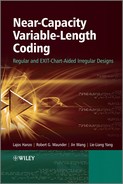
Figure 6.5: Example of a K = 5-entry VDVQ/RVLC codebook ©IEEE [194] Maunder et al. 2007.
6.3.2 VDVQ/RVLC Codebook
As stated in Section 6.2, each FD sub-frame em is approximated by the reconstructed FD sub-frame êm and represented by the bit-based transmission sub-frame um on the basis of joint VDVQ [290] and RVLC [276]. More specifically, the reconstructed FD sub-frame êm is formed as a tessellation of VQ tiles from the K-entry VDVQ/RVLC codebook, whilst the transmission sub-frame um is formed as the concatenation of the corresponding RVLC codewords from the VDVQ/RVLC codebook. The same K-entry VDVQ/RVLC codebook is employed for all VDVQ/RVLC operations of the proposed video codec, which comprises a set of VQ tiles addressed by their RVLC index representations. These are known to both the video encoder and the decoder. An example of a K = 5-entry VDVQ/RVLC codebook is provided in Figure 6.5. In the VQ tiles of this figure, dark pixels indicate negative FD values and light pixels represent positive FD values.
As exemplified in Figure 6.5, the K VQ tiles in the VDVQ/RVLC codebook may have a variety of dimensions, which must be multiples of the (8 × 8)-pixel VB dimensions. This allows the adequate representation both of small areas of high video activity and of large areas of low video activity. In this way, coding efficiency is maintained. The VDVQ/RVLC codebook entry with index k ∈ [1 ... K] is associated with the VQ tile VQk. This has the dimensions of (Jxk × Jyk) = Jk number of (8 × 8)-pixel VBs, as exemplified in Figure 6.5. However, a VQ tile’s dimensions must not exceed the MB dimensions (JxMB × JyMB) = (2 × 2) that have been employed, as defined in Section 6.3.1. Each VB VQkjk, of the set of Jk VBs that constitute the VQ tile ![]() , is allocated an index jk ∈ [1...Jk]. Note that these indices may be arbitrarily allocated. To emphasize this point, a random allocation of VB indices is employed in Figure 6.5, as exemplified by the VQ tiles VQ1 and VQ2.
, is allocated an index jk ∈ [1...Jk]. Note that these indices may be arbitrarily allocated. To emphasize this point, a random allocation of VB indices is employed in Figure 6.5, as exemplified by the VQ tiles VQ1 and VQ2.
Additionally, the VDVQ/RVLC codebook entry index k is represented by the RVLC code RVLCk, as exemplified in Figure 6.5. Each RVLC code RVLCk = ![]() comprises Ik number of bits having values of RV LCkik ∈ {0,1}, where ik ∈ [1...Ik] is the bit index. The employment of RVLC codes instead of their more efficient, higher coding-rate alternatives, such as Huffman codes [155], is justified in Section 6.3.3.
comprises Ik number of bits having values of RV LCkik ∈ {0,1}, where ik ∈ [1...Ik] is the bit index. The employment of RVLC codes instead of their more efficient, higher coding-rate alternatives, such as Huffman codes [155], is justified in Section 6.3.3.
The VDVQ/RVLC codebook should be designed by considering the statistical properties of the FD sub-frames. This can be achieved by employing the Linde–Buzo–Gray (LBG) algorithm [170] to design the VQ tile set and a Huffman-coding-based algorithm [276] to design the RVLC code set. Note that an improved performance could be expected if the VQ tile set and the RVLC code set were jointly designed in a manner similar to that of the COVQ scheme in [168, 169]. In this way, similar VQ tiles would be allocated similar RVLC codewords. However, this approach was rejected owing to the high complexity that would be required to compare the similarity of the variable-dimension VQ tiles and the variable-length codewords in various alignments and to perform the corresponding allocation.
Recall from Section 6.3.1 that all FD sub-frames exhibit similar statistical properties, but different statistical properties are exhibited by each of the J/JMB = 3 MBs that comprise the FD sub-frames. In an alternative approach, a separate VDVQ/RVLC codebook could be designed and employed to model the statistical properties of each of these MBs. This alternative approach would allow the achievement of a higher coding efficiency. However, it was discarded for the sake of simplicity.
6.3.3 VDVQ/RVLC-Induced Code Constraints
Let us now elaborate on how the employment of joint VDVQ and RVLC induces code constraints that govern the formation of legitimate bit-sequences within the transmission sub-frames. In Figure 6.6 an example of a J = 12-block reconstructed FD sub-frame êm is provided. Here, we employed the FD decomposition example of Figure 6.4 and the K = 5-entry VDVQ/RVLC codebook example of Figure 6.5. The corresponding I = 17-bit transmission sub-frame um is subject to the VDVQ/RVLC-induced code constraints outlined below.
As stated in Section 6.3.1, each reconstructed FD sub-frame êm = {êmj}Jj=1 comprises J = 12 (8 × 8)-pixel VBs. These J = 12 VBs constitute J/JMB = 3 MBs, as shown in Figure 6.6. Each of these MBs comprises an appropriate tessellation of VQ tiles from the K-entry VDVQ/RVLC codebook. The tiles VQk = {VQkjk}Jkjk=1 may cover regions of (Jxk × Jyk) = Jk number of (8 × 8)-pixel VBs. Note that in Figure 6.6 each of the entries kT, where T ∈ [Ta...Tf], invoked from the VDVQ/RVLC codebook example of Figure 6.5, provides JkT number of (8 × 8)-pixel VBs for the reconstructed FD sub-frame êm.
A specific constraint is imposed that restricts the positioning of the tile VQk in legitimate tessellations. Specifically, the Jk number of VBs in êm = {êmj}Jj=1 that are represented by the tile VQk must have consecutive VB indices j. Note that this is true in all cases in Figure 6.6. This so-called VQ tile positioning constraint is necessary to allow the formation of the novel trellis structure, as described in Section 6.3.4. In order that the video degradation imposed by this constraint is minimized, the VQ tiles and the allocation of VB indices within the MBs should be jointly designed, as stated in Section 6.3.1. In view of this, the presence of the vertical VQ tile VQ2 in the VDVQ/RVLC codebook example of Figure 6.5 motivates the vertical allocation of consecutive VB indices within each MB, as seen in Figure 6.4.
Figure 6.6: Example of a reconstructed FD sub-frame, comprising J = 12 VBs selected as exemplified in the FD decomposition of Figure 6.4, and the corresponding I = 17-bit transmission sub-frame. These comprise the entries kT from the VDVQ/RVLC codebook example of Figure 6.5, where T ∈ [Ta ... Tf] signifies the corresponding transition in the VDVQ/RVLC trellis structure example of Figure 6.7.

The employment of the VQ tile VQk is expressed using Jk number of mappings of the form êjm = VQkjk, as exemplified in Figure 6.6. With reference to the examples of Figures 6.4 and 6.5, we note that the resultant values of j ∈ [1...J] and jk ∈ [1...Jk] in such mappings are dependent on the specific positioning of the VQ tile.
Each of the VQ tiles VQk that comprise the reconstructed FD sub-frame êm is associated with a RVLC code RVLCk, where k is the VDVQ/RVLC codebook entry index. These RVLC codes are concatenated in the order of the VB indices j that are associated with the employment of the corresponding VQ tiles in the reconstructed FD sub-frame êm = {êjm}Jj=1. This is exemplified in Figure 6.6, in which each of the entries kT invoked from the VDVQ/RVLC codebook example of Figure 6.5 is represented by IkT number of bits. Note that the superscript T, where T ∈ [Ta ... Tf] in this case, denotes the corresponding transition in the associated VDVQ/RVLC trellis structure, as detailed in Section 6.3.4. In the proposed video codec each concatenation of RVLC codes is constrained to having a total length of I = 17 bits, since it constitutes the I = 17-bit transmission sub-frame um.
It follows from the above discussions that each I = 17-bit transmission sub-frame must represent a legitimate tessellation of VQ tiles, comprising J = 12 VBs in total. These VDVQ/RVLC-induced code constraints represent redundancy within the bit-based transmission sub-frames. Note that the degree of this redundancy is dependent on the distance properties of the RVLC code set employed. As outlined in Section 6.6, the employment of RVLC codes rather than Huffman codes is justified, because their additional redundancy is desirable.
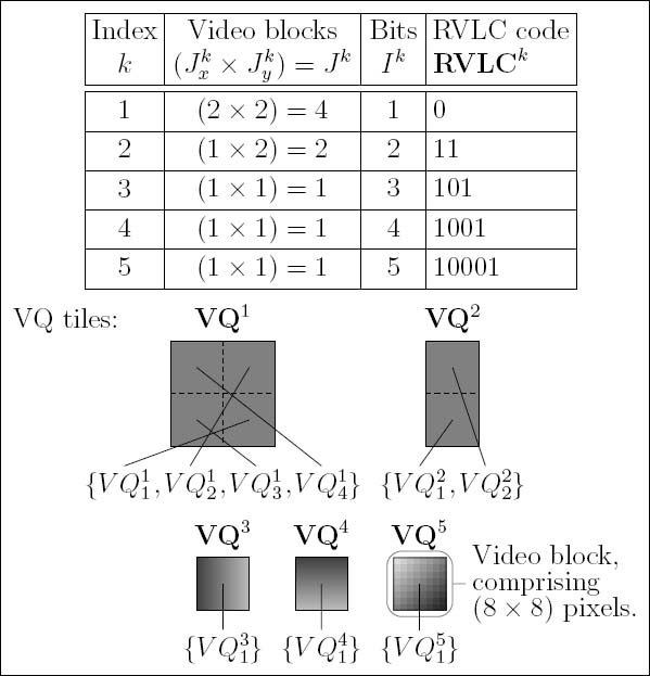
Figure 6.7: Example of a VDVQ/RVLC trellis structure for the FD decomposition example of Figure 6.4 and for the K = 5-entry VDVQ/RVLC codebook example of Figure 6.5. Trellis states occur between the consideration of specific bits and VBs; hence bit state indices ï and VB state indices ![]() occur between the bit indices i and the VB indices j respectively. ©IEEE [194] Maunder et al. 2007.
occur between the bit indices i and the VB indices j respectively. ©IEEE [194] Maunder et al. 2007.

6.3.4 VDVQ/RVLC Trellis Structure
As described in Section 6.3.3, the formation of legitimate bit-sequences within each of the bit-based transmission sub-frames is governed by the VDVQ/RVLC-induced code constraints. During VDVQ/RVLC encoding and APP SISO decoding we consider only legitimate I = 17-bit transmission sub-frame permutations. Since satisfying this constraint is non-trivial, the employment of a trellis structure is proposed to describe the complete set of VDVQ/RVLC-induced code constraints. These VDVQ/RVLC-induced code constraints depend on the FD decomposition and the VDVQ/RVLC codebook employed, as described in Section 6.3.3. Hence, the design of the proposed VDVQ/RVLC trellis structure also depends on these aspects of the proposed video codec’s operation. The VDVQ/RVLC trellis structure example of Figure 6.7 describes the complete set of VDVQ/RVLC-induced code constraints that correspond to the FD decomposition example of Figure 6.4 and to the K = 5-entry VDVQ/RVLC codebook example of Figure 6.5. In this example, each reconstructed FD sub-frame êm comprises J = 12 VBs and each transmission sub-frame um comprises I = 17 bits.
The proposed VDVQ/RVLC trellis structure comprises a set of transitions between trellis states, as exemplified in Figure 6.7. A novel block-based modification of the VLC symbol-level trellis structure described in [181] is employed. Whilst the bit index axis of [181] is retained in the proposed VDVQ/RVLC trellis structure, the VLC symbol index axis of [181] is replaced by a VB index axis. In contrast to [181], here transitions are permitted to skip a number of consecutive indices along this axis.
During a VDVQ/RVLC encoding or APP SISO decoding operation, there are a number of instances when it is possible to employ each VDVQ/RVLC codebook entry, as described below. The proposed VDVQ/RVLC trellis structure represents each of these legitimate possibilities with a transition, as exemplified in Figure 6.7. In this way, the proposed VDVQ/RVLC trellis structure describes the complete set of VDVQ/RVLC-induced code constraints. Each transition T represents a possible employment of the VDVQ/RVLC codebook entry having the index kT ∈ [1 ...K]. This is associated with a unique combination of (a) the positioning of the VQ tile VQkT within the reconstructed FD sub-frame êm and (b) the corresponding positioning of the associated RVLC code RVLCkT within the transmission sub-frame um. Note that, for reasons to be discussed below, (a) is subject to the legitimate VQ tile positioning constraint that was stated in Section 6.3.3.
Each trellis state in the proposed VDVQ/RVLC trellis structure represents the progress made at a particular point during the VDVQ/RVLC encoding or APP SISO decoding operation. This point occurs immediately after the consideration of the first ![]() number of VBs in the reconstructed FD sub-frame êm and the first ï number of bits in the transmission sub-frame um. Accordingly, trellis states are denoted S(ï,
number of VBs in the reconstructed FD sub-frame êm and the first ï number of bits in the transmission sub-frame um. Accordingly, trellis states are denoted S(ï,![]() ). Here,
). Here, ![]() ∈ [0 ... J] denotes a VB state index. These occur between the VB indices j ∈ [1 ... J] that were introduced in Section 6.3.1. Likewise, bit state indices ï ∈ [0 ... I] occur between the bit indices i ∈ [1 ... I], as shown in Figure 6.7.
∈ [0 ... J] denotes a VB state index. These occur between the VB indices j ∈ [1 ... J] that were introduced in Section 6.3.1. Likewise, bit state indices ï ∈ [0 ... I] occur between the bit indices i ∈ [1 ... I], as shown in Figure 6.7.
Each transition T represents the employment of the VDVQ/RVLC codebook entry with index kT ∈ [1 ...K] immediately after reaching a particular point during the VDVQ/RVLC encoding or APP SISO decoding operation. This point is identified by the state indices ïT ∈ [0 ... I] and ![]() T ∈ [0 ... J]. Hence, the transition T emerges from the trellis state
T ∈ [0 ... J]. Hence, the transition T emerges from the trellis state ![]() . The VQ tile VQkT provides JkT number of VBs for the reconstructed FD sub-frame êm, as stated in Section 6.3.3. Additionally, the RVLC code RVLCkT provides IkT number of bits for the transmission sub-frame um. Hence, the transition T merges into the trellis state
. The VQ tile VQkT provides JkT number of VBs for the reconstructed FD sub-frame êm, as stated in Section 6.3.3. Additionally, the RVLC code RVLCkT provides IkT number of bits for the transmission sub-frame um. Hence, the transition T merges into the trellis state ![]() . Note that the VQ tile positioning constraint described in Section 6.3.3 is necessary to ensure that each transition is continuous with respect to the VB index axis. Also note that a particular employment of a VDVQ/RVLC codebook entry is only possible if the associated transition T contributes to a legitimate transition path between the trellis states S(0,0) and S(I,J). This condition is satisfied if at least one transition path exists between the trellis states S(0,0) and
. Note that the VQ tile positioning constraint described in Section 6.3.3 is necessary to ensure that each transition is continuous with respect to the VB index axis. Also note that a particular employment of a VDVQ/RVLC codebook entry is only possible if the associated transition T contributes to a legitimate transition path between the trellis states S(0,0) and S(I,J). This condition is satisfied if at least one transition path exists between the trellis states S(0,0) and ![]() and between the trellis states
and between the trellis states ![]() and S(I,J).
and S(I,J).
Note that the reconstructed FD sub-frame and transmission sub-frame examples of Figure 6.6 correspond to the bold trellis path in Figure 6.7. Here, each transition T ∈ [Ta ... Tf] corresponds to the similarly labeled employment of a VDVQ/RVLC codebook entry in Figure 6.6. With reference to Figure 6.6, observe that each transition T ∈ [Ta ... Tf] encompasses IkT number of bit indices and JkT number of VB indices. Whilst the trellis path considered comprises six transitions, it should be noted that the trellis structure of Figure 6.7 additionally contains trellis paths comprising seven transitions. In general, each transition path in the proposed VDVQ/RVLC trellis structure comprises a varying number of transitions.
Note furthermore that, owing to the diamond shape of the VDVQ/RVLC trellis structure, a single trellis considering J · M = 396 VBs and I · M = 561 bits would contain significantly more transitions than the combination of M = 33 VDVQ/RVLC trellis structures, each considering J = 12 VBs and I = 17 bits. This justifies the decomposition of the VDVQ/RVLC encoding and APP SISO decoding operations of an entire FD into M = 33 less complex trellis-based VDVQ/RVLC operations, as described in Section 6.2.2. This decomposition is associated with a reduced grade of VDVQ/RVLC encoding freedom and hence a reduced video reconstruction quality. However, this slight video degradation is insignificant compared with the resultant computational complexity reduction.
For the benefit of the following sections, we now introduce some trellis-transition set notation, which is exemplified in Figure 6.7. The set of all transitions that encompasses (en) the VB j ∈ [1 ... J] of the reconstructed FD sub-frame êm is termed en(êmj). Furthermore, en(êmj = VQkjk) is the specific subset of en(êmj) that maps the VB jk ∈ [1 ... Jk] of the VQ tile VQk onto êmj, where k ∈ [1 ... K]. Note that some of these subsets may be empty. This is a consequence of the VQ tile positioning constraint described in Section 6.3.3. The set of all transitions that encompasses the bit i ∈ [1 ... I] of the transmission sub-frame um is termed en(umi). Additionally, en(umi = b) is the specific subset of en(umi) that maps the bit value b ∈ {0,1} onto umi. Note that, for a particular transition T, we have RVLCkTi−ïT = b if T ∈ en(umi = b). Finally, the set of transitions emerging from (fr) the trellis state S(i,ï) is denoted as fr(S(i,ï)), whilst the set merging into (to) that trellis state is represented as to(S(i,ï)).
6.4 VDVQ/RVLC Encoding
In the proposed VDVQ/RVLC-TCM scheme’s transmitter of Figure 6.1, VDVQ/RVLC encoding is performed separately for each of the M FD sub-frames. Each VDVQ/RVLC encoder operates on the basis of the proposed VDVQ/RVLC trellis structure described in Section 6.3.4 and exemplified in Figure 6.7. Since it describes the complete set of VDVQ/RVLC-induced code constraints, the employment of the proposed VDVQ/RVLC trellis structure represents the consideration of every legitimate FD sub-frame encoding. This allows us to find the MMSE approximation of the FD sub-frame em. The result is the optimal reconstructed FD sub-frame êm and the corresponding bit-based transmission sub-frame um.
We quantize the video sequence in a novel manner, which is reminiscent of [291], considering the tessellation of potentially differently sized VQ tiles. The philosophy of Viterbi decoding [193] is employed, with a survivor path being selected between the trellis state S(0,0) and every other state S(i,ï) in the trellis, as described in Chapter 3. This selection yields the ï-bit encoding of the first ![]() number of VBs in the FD sub-frame em that introduces the lowest possible cumulative video distortion D(S(ï,
number of VBs in the FD sub-frame em that introduces the lowest possible cumulative video distortion D(S(ï, ![]() )), as detailed below. This is exemplified in Figure 6.8, where a survivor path is indicated in bold between the trellis state S(0,0) and every other state S(i,
)), as detailed below. This is exemplified in Figure 6.8, where a survivor path is indicated in bold between the trellis state S(0,0) and every other state S(i,![]() ) in the trellis.
) in the trellis.
As stated in Section 6.3.4, each transition T in the proposed VDVQ/RVLC trellis structure represents the employment of the VDVQ/RVLC codebook entry with index kT during VDVQ/RVLC encoding. This corresponds to employing the VQ tile VQkT to represent a total of JkT number of (8 × 8)-pixel VBs of the FD sub-frame em. The distortion d(T) associated with the transition T is the sum of the squared difference between VQkT and the corresponding JkT number of VBs of em.
Figure 6.8: Example of MMSE VDVQ/RVLC encoding using the VDVQ/RVLC trellis structure example of Figure 6.7. The survivor path selected between the state S(0,0) and each other state S(ï,![]() ) is indicated using a bold line. Note that the survivor path selected between the trellis states S(0,0) and S(I,J) yields the FD encoding exemplified in Figure 6.6. ©IEEE [194] Maunder et al. 2007.
) is indicated using a bold line. Note that the survivor path selected between the trellis states S(0,0) and S(I,J) yields the FD encoding exemplified in Figure 6.6. ©IEEE [194] Maunder et al. 2007.
The survivor path between the trellis state S(0,0) and a particular state S(ï,![]() ) is deemed to be that associated with the specific merging transition T ∈ to(S(ï,
) is deemed to be that associated with the specific merging transition T ∈ to(S(ï,![]() )) having the minimum cumulative video distortion D(T) = d(T) + D(S(ïT,
)) having the minimum cumulative video distortion D(T) = d(T) + D(S(ïT,![]() T)), where D(S(0,0)) = 0. Note that each trellis state in Figure 6.8 has exactly one merging transition. These are indicated in bold. Having determined the survivor path at the trellis state S(I,J), the MMSE VDVQ/RVLC encoding of the FD sub-frame em has been found. The reconstructed FD sub-frame êm is formed as the tessellation of the VQ tiles associated with the survivor path transitions. Additionally, the I-bit transmission sub-frame um is formed as the concatenation of the associated RVLC codes, as described in Section 6.3.3. Note in Figure 6.8 that the survivor path selected between the trellis states S(0,0) and S(I,J) yields the reconstructed FD sub-frame êm and transmission sub-frame um of Figure 6.6.
T)), where D(S(0,0)) = 0. Note that each trellis state in Figure 6.8 has exactly one merging transition. These are indicated in bold. Having determined the survivor path at the trellis state S(I,J), the MMSE VDVQ/RVLC encoding of the FD sub-frame em has been found. The reconstructed FD sub-frame êm is formed as the tessellation of the VQ tiles associated with the survivor path transitions. Additionally, the I-bit transmission sub-frame um is formed as the concatenation of the associated RVLC codes, as described in Section 6.3.3. Note in Figure 6.8 that the survivor path selected between the trellis states S(0,0) and S(I,J) yields the reconstructed FD sub-frame êm and transmission sub-frame um of Figure 6.6.
6.5 APP SISO VDVQ/RVLC Decoding
In the proposed VDVQ/RVLC-TCM scheme’s receiver of Figure 6.2, APP SISO VDVQ/RVLC decoding is performed separately for each of the M number of I-bit transmission sub-frames. Each of the M APP SISO VDVQ/RVLC decoders operates on the basis of the proposed VDVQ/RVLC trellis structure. The recovery of legitimate – although not necessarily error-free – video information is therefore guaranteed, since the proposed VDVQ/RVLC trellis structure describes the complete set of VDVQ/RVLC-induced code constraints. As stated in Section 6.3.3, these VDVQ/RVLC-induced code constraints impose redundancy within each transmission sub-frame. This redundancy may be exploited to assist during APP SISO VDVQ/RVLC decoding by invoking the BCJR [48] algorithm on the basis of the proposed VDVQ/RVLC trellis structure. Additionally, residual redundancy is exhibited by the transmission sub-frame um owing to the simplicity of the proposed video codec. This may be exploited by the BCJR algorithm with consideration of the statistical properties of FD sub-frames, as detailed below.
Each APP SISO VDVQ/RVLC decoder is provided with the a priori LLR sub-frame Loa(um) and generates the a posteriori LLR sub-frame Lop(um), as stated in Section 6.2.3. Additionally, each APP SISO VDVQ/RVLC decoder recovers the optimal MMSE-based reconstructed FD sub-frame estimate ![]() m. This is achieved using soft APP-based reconstruction, as follows.
m. This is achieved using soft APP-based reconstruction, as follows.
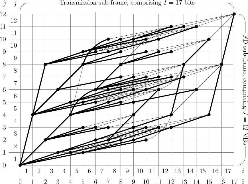
A novel block-based modification of the BCJR algorithm of [174] is invoked in the proposed VDVQ/RVLC trellis structure. This obtains an APP for each transition T, giving the probability that this specific transition was in the survivor path during the corresponding VDVQ/RVLC encoding operation, as described in Section 6.4. These APPs are calculated as

The specific value of the normalization factor C1 in Equation (6.1) may be ignored in this application, since we are only concerned with the ratios of a posteriori transition probabilities, as we show below. The terms α(S(ïT, ![]() T)), γ(T) and
T)), γ(T) and ![]() consider the probability of the requisite trellis activity before, during and after the occurrence of the transition T, respectively.
consider the probability of the requisite trellis activity before, during and after the occurrence of the transition T, respectively.
Specifically, the term γ(T) in (6.1) is calculated as

where Pa(uim = b) is the a priori probability that the transmission sub-frame bit uim has a value of b ∈ {0, 1}. This is obtained from the a priori LLR Loa(uim) = ln(Pa(uim = 0)/Pa(uim = 1)) [292]. Furthermore, P(k) in (6.1) is the probability of occurrence for the VDVQ/RVLC codebook entry with index k. This is obtained based on knowledge of the statistical properties of the FD sub-frames. As stated in Section 6.3.1, different statistical properties are associated with each of the J/JMB number of MBs constituting a FD sub-frame. Hence, different values of P(k) are employed, depending on the specific MB of which T is a constituent. Finally, the normalization factor ![]() was proposed in [174] for the sake of normalizing the VDVQ/RVLC codebook entries’ probabilities of occurrence P(k). This is necessary in the case where the VDVQ/RVLC-induced code constraints prevent the employment of one or more VDVQ/RVLC codebook entries from the state S(ï,
was proposed in [174] for the sake of normalizing the VDVQ/RVLC codebook entries’ probabilities of occurrence P(k). This is necessary in the case where the VDVQ/RVLC-induced code constraints prevent the employment of one or more VDVQ/RVLC codebook entries from the state S(ï,![]() ). For example, this is the case for the state S(2,2) of Figure 6.7, which has just four emerging transitions, indicating that only four of the K = 5 VDVQ/RVLC codebook entries can be employed.
). For example, this is the case for the state S(2,2) of Figure 6.7, which has just four emerging transitions, indicating that only four of the K = 5 VDVQ/RVLC codebook entries can be employed.
The BCJR algorithm’s forward recursion emerging from the trellis state S(0,0) is employed to obtain the values of
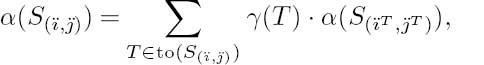
where α(S(0,0)) = 1. Similarly, a backward recursion from the trellis state S(I,J) is employed to obtain the values of

where β(S(I,J)) = 1.
Having determined the a posteriori transition probabilities, the method of [174] is employed for obtaining bit-based soft outputs for each of the I number of bits in the transmission sub-frame um = {uim}Ii=1. More specifically, an a posteriori LLR Lop(uim) is obtained for the particular bit uim with consideration of the a posteriori probabilities of all trellis transitions that may influence its value. This set of transitions en(uim) includes all transitions that bisect a cross-section of the trellis structure that is perpendicular to the bit index axis at the particular index i, as exemplified for the bit u7m in the trellis structure of Figure 6.7. The associated a posteriori LLRs are calculated as

for all i ∈ [1... I].
The recovery of the reconstructed FD sub-frame estimate ![]() m is performed on an individual block-by-block basis. A soft APP-based output is obtained for each of the J number of (8 × 8)-pixel VBs in the reconstructed FD sub-frame êm = {êjm}Jj=1. Again, a novel modification of the method of [174] is employed for obtaining these block-based soft outputs. In analogy to the generation of the previously mentioned bit-based soft outputs, the reconstruction of the particular VB êjm is performed with consideration of the a posteriori probabilities of all trellis transitions that may influence its value. This set of transitions en(êjm) includes all transitions that bisect a cross-section of the trellis structure that is perpendicular to the VB index axis at the particular index j, as exemplified for the VB êm11 in the trellis structure of Figure 6.7. The APPs of the VB êjm being provided by a particular one of the Jk number of VBs in the VQ tile
m is performed on an individual block-by-block basis. A soft APP-based output is obtained for each of the J number of (8 × 8)-pixel VBs in the reconstructed FD sub-frame êm = {êjm}Jj=1. Again, a novel modification of the method of [174] is employed for obtaining these block-based soft outputs. In analogy to the generation of the previously mentioned bit-based soft outputs, the reconstruction of the particular VB êjm is performed with consideration of the a posteriori probabilities of all trellis transitions that may influence its value. This set of transitions en(êjm) includes all transitions that bisect a cross-section of the trellis structure that is perpendicular to the VB index axis at the particular index j, as exemplified for the VB êm11 in the trellis structure of Figure 6.7. The APPs of the VB êjm being provided by a particular one of the Jk number of VBs in the VQ tile ![]() are calculated as
are calculated as

for all j ∈ [1 ... J], k ∈ [1 ... K] and jk ∈ [1 ...Jk]. Note that some of the sets ![]() may be empty, as described in Section 6.3.4. In this case, the corresponding APP is zero-valued.
may be empty, as described in Section 6.3.4. In this case, the corresponding APP is zero-valued.
Each of the J (8 × 8)-pixel VBs that constitute the reconstructed FD sub-frame estimate ![]() is obtained using optimal MMSE estimation according to the weighted
is obtained using optimal MMSE estimation according to the weighted

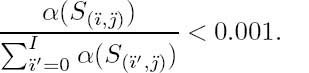
As described in Chapter 4, the logarithmic A Posteriori Probability (log-APP) algorithm [295]2 is employed to reduce the computational complexity of APP SISO VDVQ/RVLC decoding. Specifically, the above-mentioned calculations are performed in the logarithmic domain by employing the Jacobian approximation with an eight-entry table-lookup correction factor [296]. This reduces the number of multiplications required by the BCJR algorithm. Additionally, an appropriately modified reduced-complexity version of the BCJR algorithm [297] of Chapter 4 is employed to prune insignificant transitions from the proposed VDVQ/RVLC trellis structure, where the transition paths passing through the trellis state S(ï,![]() ) are pruned during the forward recursion if
) are pruned during the forward recursion if
In the next section we consider the performance of the proposed VDVQ/RVLC-TCM scheme, where the above-mentioned complexity-reduction methods were observed to impose no significant performance degradation.
6.6 Simulation Results
In this section we assess the performance of the proposed VDVQ/RVLC-TCM scheme. We transmitted 250 video frames of the ‘Lab’ video-sequence [151]. This 10 frames/s grayscale head-and-shoulders (176 × 144)-pixel Quarter Common Intermediate Format (QCIF) video sequence exhibits a moderate level of video activity.
The proposed video codec was designed to achieve an attractive trade-off between the conflicting design requirements associated with bit rate, video reconstruction quality and computational complexity. The 396-block FDs were decomposed into M = 33 FD sub-frames, each comprising J = 12 (8 × 8)-pixel VBs. This was performed exactly as exemplified in Figure 6.4. However, in contrast to our simplified example of Figure 6.7 using I = 17 bits per sub-frame, each transmission sub-frame comprised a length of I = 45 bits in the scheme implemented. A K = 512-entry VDVQ/RVLC codebook was employed. This comprised the five VQ tiles shown in Figure 6.5 and an additional 507 single-VB VQ tiles. The corresponding RVLC codes were designed to have a free distance lower bound of ![]() , since this supports iterative decoding convergence to an infinitesimally low probability of error [298], as described in Chapter 4. The lossless component of the proposed video codec’s coding rate is defined here as RVDVQ/RVLC = E/I, where I is the number of bits employed to represent each sub-frame and E is its expected sub-frame entropy, which may be estimated as
, since this supports iterative decoding convergence to an infinitesimally low probability of error [298], as described in Chapter 4. The lossless component of the proposed video codec’s coding rate is defined here as RVDVQ/RVLC = E/I, where I is the number of bits employed to represent each sub-frame and E is its expected sub-frame entropy, which may be estimated as

where −log2(P(kT)/C2(S(ïT,![]() T))) estimates the amount of information represented by the transition T in terms of bits, and P(T) is the probability of occurrence for the transition T, which is may be estimated as
T))) estimates the amount of information represented by the transition T in terms of bits, and P(T) is the probability of occurrence for the transition T, which is may be estimated as

where P(S(ï,![]() )) is the probability of occurrence for the trellis state S(ï,
)) is the probability of occurrence for the trellis state S(ï,![]() ), which may be estimated as
), which may be estimated as

For our scenario of K = 512, an approximate coding rate of RVDVQ/RVLC ≈ 0.666 is obtained.
Two VDVQ/RVLC-TCM schemes associated with different latencies were employed. The first scheme imposed a low latency equal to the duration of a single video frame, namely 0.1 s at 10 frames/s. This is suitable for real-time interactive video-telephony applications. In this scheme the length of each transmission frame u and that of the interleaver π equals M · I = 1485 bits. The second VDVQ/RVLC-TCM scheme had a high latency of 50 video frames, i.e. 5 s at 10 frames/s. This is suitable for non-real-time video streaming and wireless-Internet download applications. Here, 50 transmission frames u are concatenated before interleaving, giving an interleaver length of 50 · M · I = 74 250 bits. Note that both schemes have a video-encoded bit rate of 14.85 kbit/s.
Both VDVQ/RVLC-TCM schemes employed the same TCM codec, having the Linear Feedback Shift Register (LFSR) schematic of Figure 6.9. As shown in Figure 6.9, the TCM encoder generates a set of four bits to represent each set of three input bits, giving a coding rate of R TCM = 3/4. Three of the four output bits are systematic replications of the three input bits, whilst the fourth output bit is generated with the aid of the LTCM = 6 modulo-2 memory elements. Note that the TCM codec is a recursive component having an infinite impulse response, since feedback is employed in the shift register of Figure 6.9. As a result, the TCM codec supports iterative decoding convergence to an infinitesimally low probability of error [299], as is the case for our VDVQ/RVLC codec, as described above. Hence, we may expect the proposed VDVQ/RVLC-TCM scheme to achieve iterative decoding convergence to an infinitesimally low probability of error, provided that the channel quality is sufficiently high to create an open EXIT chart tunnel and the iterative decoding trajectory approaches the inner and outer EXIT functions sufficiently closely, as discussed in Chapter 4. Furthermore, Figure 6.10 provides the constellation diagram for the MTCM = 16-ary set-partitioned [277] Quadrature Amplitude Modulation (QAM) modulation scheme of the TCM codec. This was employed together with In-phase Quadrature-phase (IQ)-interleaving [293] for transmission over an uncorrelated narrowband Rayleigh fading channel.
Figure 6.9: LFSR encoder schematic for the recursive systematic RTCM = 3/4-rate TCM codec employing a coding memory of LTCM = 6.
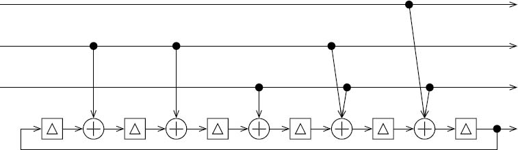
Figure 6.10: Constellation diagram for the MTCM = 16-level set partitioned QAM modulation scheme. For an average transmit energy of unity, ![]()

The effective throughput of the proposed VDVQ/RVLC-TCM scheme is given by η = RVDVQ/RVLC × RTCM × log2(MTCM) ≈ 2.00bits per channel use. Note that for η = 2.00 bits per channel use, the uncorrelated Rayleigh-fading channel’s capacity for 16-ary Quadrature Amplitude Modulation (16QAM) is reached for a Rayleigh fading channel SNR of 6.96 dB [300].
In the EXIT chart of Figure 6.11 we provide the EXIT functions [294] for APP SISO TCM decoding at various channel SNR values, as described in Chapter 4. These were generated using Gaussian distributed a priori LLRs and all mutual information measurements were made using the histogram-based approximation of the LLR Probability Density Functions (PDFs) [294], as described in Chapter 4. Note that, owing to its recursive nature, the APP SISO TCM decoder is capable of achieving unity extrinsic mutual information Iie for unity a priori mutual information Iie [299]. Additionally, Figure 6.11 provides the inverted APP SISO VDVQ/RVLC decoding EXIT function. Note that, according to the proof of [204], the area beneath the inverted APP SISO VDVQ/RVLC decoding EXIT function is equal to the lossless coding rate of the VDVQ/RVLC codec RVDVQ/RVLC. This area was found to be 0.666, which confirms the calculation provided above. Similarly to APP SISO TCM decoding, APP SISO VDVQ/RVLC decoding achieves unity extrinsic mutual information Ioe, for unity a priori mutual information Ioe, owing to the employment of a RVLC code set having a free distance lower bound of ![]() , as discussed in Chapter 3. Hence an open EXIT chart tunnel [267] can be created, if the channel SNR is sufficiently high. If the iterative decoding trajectory approaches the inner and outer EXIT functions sufficiently closely, iterative decoding convergence to unity mutual information will be achieved in this case. This is associated with an infinitesimally low probability of error, as described in Chapter 4. Since our objective is to mitigate all transmission errors in this way, it is for this reason that we do not employ any additional measures to counteract the propagation of distortion amongst consecutive differentially encoded video frames, as described in Section 6.2.1.
, as discussed in Chapter 3. Hence an open EXIT chart tunnel [267] can be created, if the channel SNR is sufficiently high. If the iterative decoding trajectory approaches the inner and outer EXIT functions sufficiently closely, iterative decoding convergence to unity mutual information will be achieved in this case. This is associated with an infinitesimally low probability of error, as described in Chapter 4. Since our objective is to mitigate all transmission errors in this way, it is for this reason that we do not employ any additional measures to counteract the propagation of distortion amongst consecutive differentially encoded video frames, as described in Section 6.2.1.
As shown in Figure 6.11, the proposed VDVQ/RVLC-TCM scheme exhibits an open EXIT chart tunnel for channel SNRs above a threshold of 8.25 dB, which is just 1.29 dB from the proposed VDVQ/RVLC-TCM scheme’s SNR capacity bound of 6.96 dB. As described in Chapter 4, an open EXIT chart tunnel implies that iterative decoding convergence to an infinitesimally low video degradation may be achieved, again provided that the iterative decoding trajectory approaches the inner and outer EXIT functions sufficiently closely. Note that an open EXIT tunnel would be achieved for a lower channel SNR that is closer to the channel’s SNR capacity bound of 6.96 dB, if the shape of the APP SISO VDVQ/RVLC decoder’s inverted EXIT function was better matched to that of the APP SISO TCM decoder’s EXIT function, as discussed in Chapter 4. This would naturally result in an EXIT chart tunnel that was narrow all along its length. Despite this, however, the APP SISO VDVQ/RVLC decoder’s inverted EXIT function of Figure 6.11 does offer a fairly good match with the APP SISO TCM decoder’s EXIT function for a channel SNR of 8.25 dB, resulting in an EXIT chart tunnel that is fairly narrow along its entire length.
Figure 6.11 additionally provides EXIT trajectories [294] that were averaged over all 250 source video frames for both the 1485-and the 74 250-bit interleaver VDVQ/RVLCTCM schemes at a channel SNR of 9 dB. The 1485-bit interleaver trajectory can be seen to deviate from the EXIT functions and fails to converge to the desired unity mutual information. By contrast, the 74 250-bit interleaver trajectory offers an improved correlation with these EXIT functions and converges to unity mutual information. The improved performance of the 74 250-bit interleaver scheme is a benefit of its more uncorrelated a priori information [292], justified by the reasons noted in Section 6.2.3. Note however that an iterative decoding trajectory offering an even better match with the inner and outer EXIT functions may be expected for interleaver lengths higher than 74 250 bits.
Figure 6.11: The proposed VDVQ/RVLC-TCM scheme’s EXIT chart for the ‘Lab’ video sequence and a 3/4-rate TCM scheme. ©IEEE [194] Maunder et al. 2007.

In Figure 6.12, the video reconstruction quality of both the 1485-and the 74 250-bit interleaver VDVQ/RVLC-TCM schemes is assessed after a number of decoding iterations and for a range of channel SNR values. We employ the Peak Signal-to-Noise Ratio (PSNR) [151] as the objective video reconstruction quality metric. In this application, a PSNR of 29.5 dB is associated with an aesthetically pleasing video reconstruction quality. The proposed VDVQ/RVLC-TCM scheme exhibited substantial iteration gains, as shown in Figure 6.12. After eight decoding iterations a SNR iteration gain of 4.34 dB was achieved by the 1485-bit interleaver scheme at a PSNR of 29.5 dB. In the case of the 74 250-bit interleaver scheme, the corresponding iteration gain was 5.61 dB. The 74 250-bit interleaver scheme was seen to outperform the 1485-bit interleaver scheme, regardless of the number of decoding iterations. This is in agreement with the findings of the EXIT chart analysis of Figure 6.11, as discussed above. For the 1485-bit interleaver scheme, a PSNR higher than 29.5 dB was achieved after eight decoding iterations for channel SNRs greater than 10.00 dB, as shown in Figure 6.12. This is 3.04 dB from the proposed VDVQ/RVLC-TCM scheme’s channel’s SNR capacity bound of 6.96 dB. In the case of the 74 250-bit interleaver scheme, this is achieved for channel SNRs higher than 8.75 dB, which is just 1.79 dB from the channel’s capacity bound. Note that if an even longer interleaver were employed, a PSNR in excess of 29.5 dB might be expected for channel SNRs that are even closer to the 8.25 dB threshold at which an open EXIT chart tunnel is achieved, as discussed above. Naturally, this would be associated with an even higher latency, however.
Figure 6.12: PSNR performance of the proposed VDVQ/RVLC-TCM scheme as well as of the VQ- andMPEG-4-based benchmarks for the ‘Lab’ video sequence, when communicating over an uncorrelated narrowband Rayleigh fading channel. ©IEEE [194] Maunder et al. 2007.

We now compare the performance of the proposed VDVQ/RVLC-TCM scheme with two benchmarks. Similarly to the proposed VDVQ/RVLC-TCM scheme, the scheme of [273] is also VQ-based and it is hence referred to as the VQ-based benchmark here. In contrast, the IQ-TCM-RVLC scheme of [274] is based upon the MPEG-4 video coding standard [158], and is referred to here as the MPEG-4-based benchmark. Similarly to the proposed VDVQ/RVLC-TCM scheme, the benchmarks employ both RVLC and TCM. However, they adopt Shannon’s source and channel coding separation philosophy [133], with video decoding being performed independently of iterative channel decoding, as described in Section 6.1. Since the same input video sequence, latency, coding rate, bit rate and channel were employed for both of the benchmarks as well as for the 1485-bit interleaver VDVQ/RVLC-TCM scheme, their direct comparison is justified.
In Figure 6.12, the 1485-bit interleaver VDVQ/RVLC-TCM scheme can be seen to outperform the VQ-based benchmark, regardless of the number of decoding iterations. Although the MPEG-4-based benchmark achieves a slightly higher error-free video reconstruction quality than does the proposed VDVQ/RVLC-TCM scheme, it is outperformed by the scheme advocated at low values of channel SNR. At a PSNR of 29.5 dB, the proposed VDVQ/RVLCTCM scheme offers a consistent improvement over both the VQ-and the MPEG-4-based benchmarks, amounting to about 1.1 dB and 1.6 dB respectively. This is a benefit of the iterative exploitation of the video codec’s code constraints, as outlined in Section 6.5. Additionally, this approach guarantees the recovery of legitimate video information. Hence, the proposed VDVQ/RVLC-TCM scheme is never forced to discard any video information. In contrast, both the benchmarks of [273] and [274] drop video frames when the iterative decoding process does not recover legitimate video information, reducing the attainable video reconstruction quality.
The improved performance offered by the proposed VDVQ/RVLC-TCM scheme is achieved at the cost of an increased computational complexity. A simple metric of computational complexity considers the number of BCJR trellis transitions encountered during iterative decoding. Note that this ignores the complexity contribution imposed by trellis pruning and video reconstruction. Although an equal number of BCJR transitions are employed during APP SISO TCM decoding in the proposed VDVQ/RVLC-TCM scheme and in the benchmarks, the complexities of the respective VDVQ/RVLC and RVLC APP SISO decoding operations are different. More explicitly, in the proposed VDVQ/RVLCTCM scheme the APP SISO VDVQ/RVLC decoding employs a channel-condition-dependent number of BCJR transitions, which is typically equal to the number of trellis transitions encountered during APP SISO TCM decoding. In contrast, the benchmarks’ bit-level RVLC decoding trellises [301] have approximately a quarter of this number of trellis transitions, as discussed in Chapter 3. Hence, the proposed VDVQ/RVLC-TCM scheme has a computational complexity that may be deemed to be approximately 1.6 times that of the benchmarks.
6.7 Summary and Conclusions
In this chapter we have considered the application of joint source and channel coding for video transmission. More specifically, a novel VDVQ-and RVLC-based video codec was serially concatenated with TCM and was iteratively decoded, as described in Section 6.2. The proposed video codec imposed the code constraints of Section 6.3.3, specifying which particular VQ tiles and which RVLC codewords may be employed at which stages of the video coding process. Since the set of valid RVLC codewords varies throughout the video coding process, this chapter therefore exemplifies the application of IrVLC schemes in the context of joint source and channel coding.
In the proposed video codec, the complete set of VDVQ/RVLC-induced code constraints was described by the novel VDVQ/RVLC trellis structure of Section 6.3.4. Hence, the employment of the VDVQ/RVLC trellis structure allows the consideration of all legitimate transmission frame permutations. This fact was exploited in the transmitter of the VDVQ/RVLC-TCM scheme in order to perform novel MMSE VDVQ/RVLC encoding, as described in Section 6.4. Additionally, the employment of the VDVQ/RVLC trellis structure during VDVQ/RVLC decoding was shown in Section 6.5 to guarantee the recovery of legitimate – although not necessarily error-free – video information. This ensured that useful video information was never discarded, unlike in conventional video decoders, where a single transmission error may render an entire transmission frame invalid. A novel modification of the BCJR algorithm was employed during APP SISO VDVQ/RVLC decoding in order to facilitate the iterative exchange of soft information with the serially concatenated APP SISO TCM decoder and to perform the soft MMSE reconstruction of the video sequence. Since the VDVQ/RVLC trellis structure describes the complete set of VDVQ/RVLC-induced code constraints, all of the associated redundancy was beneficially exploited with the aid of the modified BCJR algorithm.
In Figure 6.11 the proposed VDVQ/RVLC-TCM scheme was shown to support iterative decoding convergence to an infinitesimally low video degradation for channel SNRs in excess of 8.25 dB, provided that the iterative decoding trajectory approaches the inner and outer EXIT functions sufficiently closely. Note that this is just 1.29 dB from the 16QAMbased Rayleigh fading channel’s SNR capacity bound of 6.96 dB, which corresponds to an effective throughput of 2.00 bits per channel use. It was noted however that iterative decoding convergence to an infinitesimally low video degradation could be supported at channel SNRs that are closer to the SNR capacity bound, if the APP SISO VDVQ/RVLC decoder’s inverted EXIT function shown in Figure 6.11 was better matched to the EXIT function of the APP SISO TCM decoder. Hence, we design IrVLCs with the aid of EXIT-chart matching in Chapters 7–9 using a procedure that was briefly introduced in Section 5.5.3 in the context of IRCCs.
Using an interleaver length of 74 250 bits, it was shown in Figure 6.12 that the ‘Lab’ video sequence encoded at a bit rate of 14.85 kb/s was reconstructed with a PSNR of at least 29.5 dB for channel SNRs in excess of 8.75 dB, which is 1.79 dB from the channel’s capacity bound. It was also noted that if an even longer interleaver were employed, then the proposed scheme would support operation at channel SNRs that are even closer to the threshold at which an open EXIT chart tunnel can be obtained. This is because a longer interleaver would facilitate the mitigation of more correlation within the iteratively exchanged extrinsic information, resulting a better match between the iterative decoding trajectory and the inner and outer EXIT functions of Figure 6.11. Hence, the employment of longer interleavers is investigated in Chapters 7–9.
In Figure 6.12, the joint source and channel coding approach of the proposed VDVQ/RVLC-TCM scheme was shown to consistently outperform two powerful benchmarks, both employing the Shannonian source and channel coding separation philosophy. However, this performance improvement was found to accrue at the cost of a 1.6 times higher computational complexity. This was attributed to the APP SISO VDVQ/RVLC decoder’s employment of the VDVQ/RVLC trellis structure of Section 6.3.4, which resembles a symbol-based VLC trellis, as described in Chapter 3. By contrast, the benchmarks employ bit-based VLC trellises in the corresponding role, having a lower complexity, as discussed in Chapter 3. In the light of this, we characterize and compare the complexity associated with employing bit-and symbol-based trellises for APP SISO VLC decoding in Chapter 7.
1Part of this chapter is based on [194] © IEEE (2007).
2The log-APP algorithm is also known as the logarithmic Maximum A Posteriori (log-MAP) algorithm.