
8
Voltage Transformers
Voltage transformers (VTs), or potential transformers (PTs) as they are also called, are used to provide a scaled representation of the potentials on MV or HV busses, one that may conveniently be handled by protection relays, energy meters and general instrumentation equipment. Depending on the intended application, VTs may either be connected to system phase voltages or across line voltages. Therefore a VT’s primary rating must be appropriate to both the bus potential and its intended method of connection.
Because a VT’s secondary voltage is ideally a scaled replica of the bus voltage to which it is connected, it is important that the device does not introduce errors of its own into the measurement. Accordingly, manufacturers limit the burden that may be connected to the secondary winding(s), so as to reduce the potential dropped across the transformer’s short‐circuit impedance. Therefore the rated burden current is generally well below the thermal current limit of a VT. Despite this, magnitude and phase errors are introduced into the secondary voltages, but provided they are kept sufficiently small, their effects can be accepted. These errors are more of a problem in metering than in protection applications, since they directly affect the accuracy of the metered data. Limitations on the errors introduced are imposed by the various metering class designations.
Voltage transformer secondary potentials generally take one of several standardised voltages, as outlined in Table 8.1. With the exception of line connected VTs used in two element metering applications, modern voltage transformers tend to be phase connected, i.e. between phase and ground potential. In addition, they are generally single‐phase devices, and are therefore capable of supporting a zero‐sequence voltage, should one exist. This feature is important in protection applications. (Three‐phase, three‐limb VTs generally do not have this ability.) Despite being phase connected the voltage ratio is usually specified in terms of the rated line voltage of the associated bus, thus a 132 kV VT will have its ratio specified as: 132 /√3 kV:110/√3 V.
Table 8.1 Voltage Transformer standard secondary voltages.
(IEC 61869‐3 ed.1.0 Copyright © 2011 IEC Geneva, Switzerland. www.iec.ch)
| Location | Secondary line voltages | Secondary phase voltages |
| Europe | 100 V and 110 V | 100/√3 V and 110/√3 V |
| Europe (extended secondary circuits) | 200 V | 200/√3 V |
| China | 100 V | 100/√3 V |
| USA & Canada (distribution) | 120 V | 120/√3 V |
| USA & Canada (transmission) | 115 V | 115/√3 V |
| USA & Canada (extended secondary circuits) | 230 V | 230/√3 V |
8.1 Inductive and Capacitive Voltage Transformers
Voltage transformers broadly fall into two categories, single‐ and three‐phase inductive (iron cored) VTs and single‐phase capacitive VTs. Medium voltage transformers usually fall into the former category, and are built in a similar fashion to small single‐ or three‐phase distribution transformers. Three‐phase devices are often oil immersed, while single‐phase VTs designed to be incorporated into metal clad switchgear, are usually resin cast. High voltage VTs on the other hand are increasingly of the single‐phase capacitive type. These use a capacitive voltage divider to reduce the potential supplied to an iron‐cored transformer, and by so doing make its design less expensive.
The voltage transformer in Figure 8.1 is a resin cast, single‐phase, three‐winding inductive device. The 11 kV HV terminal can be seen on top, and the secondary terminals are at the lower front. The low voltage end of the primary winding also frequently appears with these terminals, and it is very important that it remains grounded while the VT is in service. Its nameplate shows that this VT is designed to be connected to a primary potential of 11000/√3 V (6350 V). Each of its secondary windings delivers a phase voltage of 110/√3 V (63.5 V) and has a VA rating of 10 VA, which means that the minimum burden impedance that may be connected to any winding is ![]() ohms. One of these windings is a protection class (1P) winding while the other two are metering class (0.2 M). The thermal rating for each secondary winding is 2 A, beyond which overheating may occur. While it is common for modern VTs to be equipped with two secondary windings, it is unusual for a VT to have three. This particular device was built to an old Australian standard (AS1243, Voltage Transformers for Measurement and Protection, 1982) and was one of several provided to a large customer who required independent revenue and check metering class windings, in addition to a protection class winding.
ohms. One of these windings is a protection class (1P) winding while the other two are metering class (0.2 M). The thermal rating for each secondary winding is 2 A, beyond which overheating may occur. While it is common for modern VTs to be equipped with two secondary windings, it is unusual for a VT to have three. This particular device was built to an old Australian standard (AS1243, Voltage Transformers for Measurement and Protection, 1982) and was one of several provided to a large customer who required independent revenue and check metering class windings, in addition to a protection class winding.

Figure 8.1 Three‐winding 11 kV VT together with its nameplate.
Figure 8.2 shows a single‐phase capacitive voltage transformer (CVT), designed to operate on a phase voltage of 220/√3 kV. Its HV terminal is internally connected to a capacitive voltage divider (C1, C2), the output of which supplies an oil immersed medium voltage inductive transformer (the intermediate transformer). The Thévenin equivalent impedance of this divider is equal to the reactance of the parallel capacitor combination (C1, C2). These capacitors are relatively small, and were this impedance not compensated for, the transformer would exhibit particularly poor voltage regulation.

Figure 8.2 (a) A 220 kV capacitive voltage transformer (CVT) (b) CVT equivalent circuit.
(IEC 61869‐5 ed.1.0 Copyright © 2012 IEC Geneva, Switzerland. www.iec.ch).
The Thévenin equivalent impedance forms a series circuit, resonant at the supply frequency, with the compensation inductance, shown in Figure 8.2. This may be a discrete inductance or it may comprise the leakage inductance of the intermediate transformer. By creating this resonance, the effects of the Thévenin impedance can be annulled, and the iron‐cored transformer effectively becomes fed from a low impedance source.
Because of the difficulty in achieving tight tolerances in the values of C1 and C2, tappings are often included on the intermediate transformer to provide a degree of ratio adjustment. The compensation inductance must similarly be adjustable.
For frequencies close to the system frequency a capacitive VT performs well, its magnitude and phase errors depending largely on the short‐circuit impedance of the inductive transformer. However, at frequencies remote from the system frequency, the voltages reported by capacitive VTs will contain errors and cannot be relied upon; these devices therefore find limited application in harmonic studies.
8.1.1 Winding Arrangements
Because the secondary voltages must be a scaled representation of the associated primary potentials, voltage transformers are usually connected in a star‐star (wye‐wye) configuration, which allows both phase and line voltages to be measured. Occasionally a delta‐delta connection is used in situations where line voltages alone are sufficient for the intended application, particularly in ungrounded or high impedance grounded networks. In both these arrangements there is no significant phase shift introduced between the primary and secondary potentials.
There is also a third connection that is used in protection applications. This relates to the detection of residual or zero‐sequence voltages, arising during fault conditions. Residual voltage transformers have a grounded star connected primary; their secondary windings are connected in an open delta arrangement, across which the residual voltage appears (Figure 8.3). A residual VT may be constructed using three single‐phase transformers or alternatively it may be based on a three‐phase transformer. In the latter case a five‐limb core (i.e. a shell type core) must be used, so that a zero‐sequence flux can be supported, as required to generate the zero‐sequence voltage in each winding. The residual voltage developed across the open delta will thus be equal to three times the zero‐sequence voltage.

Figure 8.3 Open delta connection for the detection of residual voltages.
8.2 Voltage Transformer Errors
All voltage transformers introduce small errors into their representations of the applied primary voltage. These are generally not critical in protection applications, but any introduced error will directly affect the accuracy of metering circuits. As a result, voltage transformers used in metering applications fall into various classes according to the size of these errors, as defined in the appropriate standard.
Magnitude error, as its name suggests, relates to the magnitude difference between the actual secondary voltage of a given voltage transformer and that which an ideal transformer would produce. Similarly, the phase error represents the angular difference between the actual secondary voltage and that produced by an ideal device. The magnitude and phase errors associated with both the voltage and current transformers used in energy metering circuits introduce errors into the energy measured. In order to achieve a required accuracy of measurement, these transformers must therefore be of an appropriate accuracy class. For example, in order to correctly meter energy to an accuracy of ±0.5%, class 0.2 voltage and current transformers will generally be required.
Magnitude Error Definition
The magnitude error e (sometimes called the ratio error) is defined as:

where Vpri is the actual primary voltage, Vsec is the actual secondary voltage, and N is the nominal turns ratio (Vrated pri /Vrated sec)
Therefore a VT with a magnitude error of +0.2% presents a secondary voltage which is in excess of the actual voltage by this amount.
Phase Error Definition
The phase error γ, is the difference in phase between the primary voltage phasor and the secondary voltage phasor. The phase error is defined as positive when the secondary voltage phasor leads that of the primary.
Phase errors are usually measured in either minutes of arc or centiradians. (1 Crad = 34.4 minutes of arc.)
(Radian measure is based on the arc length subtended by a radius, R. An angle expressed in radians is defined as the length of the enclosed arc divided by the radius. For example, a semicircle of radius R subtends an arc of length πR and therefore the subtended angle of 180° is equal to π radians. Thus one radian is equal to 57.3°. A centiradian is one hundredth of a radian, and equals 0.573° or 34.4 minutes of arc.)
The magnitude and phase errors, as defined under IEC standards, are independent of one another, and as we shall see, they can be related to the short‐circuit impedance of the voltage transformer concerned. To ensure compliance with these standards, the magnitude and phase errors must lie within the appropriate rectangle shown in Figure 8.4.

Figure 8.4 Magnitude and phase error limits for classes 0.2, 0.5 and 1.0.
(IEC 61869‐3 ed.1.0 Copyright © 2011 IEC Geneva, Switzerland. www.iec.ch).
8.2.1 Voltage Transformer Standards
We shall confine our interest in voltage transformer standards to three documents, the first two of which are European standards: IEC61869‐3 Additional Requirements for Inductive Voltage Transformers and IEC61869‐5 Additional Requirements for Capacitor Voltage Transformers. The third is the American standard IEEE C57.13 IEEE Standard Requirements for Instrument Transformers, including its supplement, IEEE C57.13.6 IEEE Standard for High‐Accuracy Instrument Transformers. The last two documents apply to both voltage and current transformers. Both the European and American standards define the requirements of voltage transformers for both metering and protection applications. We will initially consider the requirements for metering class VTs as defined by each standard.
8.2.2 Magnitude and Phase Errors Defined under IEC 61869‐3 and IEC 61869‐5
IEC 61869‐3 and IEC61869‐5 define magnitude and phase error limits for VTs used in metering applications according to Table 8.2. Five classes of voltage transformer are defined. Class 0.1 applies to inductive laboratory grade instruments, and will not generally be found in metering applications. Classes 0.2 and 0.5 and 1.0 are prescribed for revenue metering applications, while class 3.0 is generally only used for panel instrumentation.
Table 8.2 Accuracy class limits for metering classes 0.1 – 3.0.
(IEC 61869‐3 ed.1.0 Copyright © 2011 IEC Geneva, Switzerland. www.iec.ch)
| Metering class | Magnitude error limits | Phase error limits | |
| 0.1* | ±0.1% | ±5 minutes | ±0.15 Crad |
| 0.2 | ±0.2% | ±10 minutes | ±0.30 Crad |
| 0.5 | ±0.5% | ±20 minutes | ±0.60 Crad |
| 1.0 | ±1.0% | ±40 minutes | ±0.1.2 Crad |
| 3.0 | ±3.0% | Not specified | Not specified |
Table 8.3 defines the standard burden ratings for voltage transformers. Two ranges are prescribed: range I applies to very lightly loaded transformers, typical of modern metering or protection equipment: these burdens are assumed to be resistive. Range II applies to more traditional VTs where a heavier burden must be supported, one that is partially inductive. The error limits outlined in Table 8.2 apply for 0–100% of the rated burden for range I, and 25–100% of rated burden for range II. Burden ratings specified under IEC 61869‐3 apply to each winding on a voltage transformer.
Table 8.3 Voltage transformer standard burdens as defined in IEC 61869‐3.
(IEC 61869‐3 ed.1.0 Copyright © 2011 IEC Geneva, Switzerland. www.iec.ch)
| Burden range | Rated burden (VA) | Burden power factor | Compliance range (% of rated burden) |
| I | 1.0, 2.5, 5, 10 | 1.0 | 0–100 |
| II | 10, 25, 50, 100 | 0.8 | 25–100 |
Finally, the prescribed error limits must be maintained for voltages within the range 0.8–1.2 pu, and in the case of capacitive voltage transformers, over a frequency range of 99% to 101% of the nominal device frequency (50 or 60 Hz.)
8.2.3 Ratio and Phase Errors Defined under IEEE C57.13
The American standard IEEE C57.13 defines three standard classes of metering transformer (0.3, 0.6, 1.2) and its supplement IEEE C57‐13.6, defines a further high accuracy class, 0.15. This standard does not directly prescribe magnitude and phase errors, but rather places limits on a related quantity known as the transformer correction factor (TCF).
As mentioned above, any magnitude or phase errors inherent in the associated VT will introduce a small error into the measurement of the power or energy flowing. This error may be corrected using the transformer correction factor, which may be calculated from the ratio correction factor (RCF), the phase error γ of the associated VT, and the phase angle of the metered load ϕ, using:

(Note that this equation does not include the errors associated with the current transformers (CTs) used in the metering installation.)
The RCF is defined as the factor by which the stated ratio of an instrument transformer must be multiplied to obtain the actual ratio. Therefore the RCF can be used to correct the measured voltage presented by a VT for the effects of magnitude error, as follows:

where Vmeasured, is the voltage measured by the VT in question, and Vcorrect is this quantity corrected for the magnitude error introduced by the VT. The RCF is related to the magnitude error e, according to:

For example, if the magnitude error, e = +0.2%, then the associated RCF will be 0.998.
IEEE C57.13 prescribes limits on the TCF, which appear in Table 8.4. These must be maintained from 0% to 100% of the transformer’s rated burden, for metered loads with lagging power factors between 0.6 and 1.0. They must also be maintained over a range of applied voltages between 0.9 and 1.1 pu.
Table 8.4 Accuracy class limits for metering classes 0.15 to 1.2.
(Adapted and reprinted with permission from IEEE. Copyright IEEE C57.13 (2008) All rights reserved. Permission for further use of this material must be obtained from IEEE. Requests may be sent to stds‐[email protected])
| Metering Class | Transformer correction factor (TCF) | |
| Minimum | Maximum | |
| 0.15 | 0.9985 | 1.0015 |
| 0.3 | 0.997 | 1.003 |
| 0.6 | 0.994 | 1.006 |
| 1.2 | 0.988 | 1.012 |
Prescribing limits applicable to the TCF indirectly places limits on both the RCF and the phase error of a VT. The TCF is largest when the power factor of the metered load the lies at the lower end of the permitted range, i.e. when it equals 0.6. Under these conditions Equation (8.3) defines the relationship between these parameters. (This is fully discussed in Chapter 10.)
As a result, the ratio correction factor and the phase error are no longer independent of each other, and instead are constrained to lie within the parallelogram appropriate to the class of the VT, as shown in Figure 8.5.

Figure 8.5 Voltage transformer ratio correction factor and phase error limits.
(Adapted and reprinted with permission from IEEE. Copyright IEEE C57.13 (2008) All rights reserved. Permission for further use of this material must be obtained from IEEE. Requests may be sent to stds‐[email protected]).
IEEE C57.13 defines a list of standard burdens for voltage transformer accuracy testing, as shown in Table 8.5. For voltages different from those listed in the table, the burden impedance can be calculated according to ![]() . The accuracy class for a particular voltage transformer is specified in conjunction with a standard burden designation. For example, class 0.3ZZ implies that the transformer satisfies the 0.3 class accuracy requirements with a 400 VA burden of 0.85 pf. It will also be compliant with lower designations of the same power factor; however 0.3 class accuracy is not necessarily maintained for lower burden designations of a different power factor.
. The accuracy class for a particular voltage transformer is specified in conjunction with a standard burden designation. For example, class 0.3ZZ implies that the transformer satisfies the 0.3 class accuracy requirements with a 400 VA burden of 0.85 pf. It will also be compliant with lower designations of the same power factor; however 0.3 class accuracy is not necessarily maintained for lower burden designations of a different power factor.
Table 8.5 Standard voltage transformer burdens.
(Adapted and reprinted with permission from IEEE. Copyright IEEE C57.13 (2008) All rights reserved. Permission for further use of this material must be obtained from IEEE. Requests may be sent to stds‐[email protected])
| Burden designation | VA rating | Burden power factor | Impedance at 120 V (line voltage) ohms |
Impedance at 69.3 V (phase voltage) ohms |
| W | 12.5 | 0.1 | 1152 | 384 |
| X | 25 | 0.7 | 576 | 192 |
| M | 35 | 0.2 | 411 | 137 |
| Y | 75 | 0.85 | 192 | 64 |
| Z | 200 | 0.85 | 72 | 24 |
| ZZ | 400 | 0.85 | 36 | 12 |
8.3 Voltage Transformer Equivalent Circuit
The equivalent circuit of a voltage transformer can be used to derive expressions for both the magnitude and phase errors. A simplified equivalent circuit appears in Figure 8.6, where all circuit elements have been referred to the low voltage (secondary) winding. The resistive component of the short‐circuit impedance r relates to the winding resistances, while the inductive reactance x arises due to the leakage flux generated by each winding that does not link the other. The magnitude error is a function of the turns ratio, the short‐circuit impedance and the burden applied to the VT.

Figure 8.6 Simplified voltage transformer equivalent circuit, including inductive burden.
X M represents the inductance through which the magnetising current flows in order to establish the required flux in the core, while RM reflects the associated hysteresis and eddy current losses within the core. The magnetising impedance will depend to a small extent on the magnitude of the applied primary voltage; however, these components generally only have a very small influence on the device errors over the normal range of operating voltages.
In general, the applied burden will be slightly inductive, although in recent years the trend towards electronic energy meters and numerical protection relays has seen many voltage transformers become resistively loaded, and frequently very lightly. Burden range I in Table 8.3 is designed to reflect this. The parallel combination of RB and XB therefore reflects a slightly inductive burden. Except for the special case of zero burden, we find that ![]() , so the magnetising impedance can usually be neglected.
, so the magnetising impedance can usually be neglected.
8.3.1 Turns Compensation in Voltage Transformers
Because the secondary voltage of any VT falls slightly when it is burdened, manufacturers generally apply some additional turns to the secondary winding, in order to slightly increase the magnitude of the secondary voltage. This permits an increase in the burden that can be applied before the magnitude error falls outside the lower class limit, at the expense of creating positive magnitude errors when small burdens are applied. This technique, called turns compensation, usually results in an actual turns ratio between 0.2% and 1.0% greater than the nominal ratio, depending on the class of the VT. Turns compensation has a marked effect on the magnitude error of the device, but makes no difference to the phase error.
8.3.2 VT Magnitude Error Equation
The voltage across the secondary terminals (S1, S2) depends on the actual turns ratio used (Nact), the short‐circuit impedance (r + jx) and the burden connected between S1 and S2. We will show that provided , then the magnitude error can be expressed to a very good approximation as:

where e = the magnitude error in %, N = the nominal turns ratio, E1 rated/E2 rated, Nact = the actual turns ratio, n1/n2, RB = the resistive component of the burden, XB = the inductive component of the burden, r = the resistive component of the short‐circuit impedance and x = the inductive component of the short‐circuit impedance.
The ratio ![]() is the normalised turns ratio, and typically lies between 1.002 and 1.01. Equation (8.4) may be derived from the secondary circuit phasor diagram shown in Figure 8.7. The burden voltage V2 has been chosen as the reference phasor, and the inductive burden current IB lags this by an angle ϕB. We resolve this current into an in‐phase component V2/RB and a quadrature component V2/XB.
is the normalised turns ratio, and typically lies between 1.002 and 1.01. Equation (8.4) may be derived from the secondary circuit phasor diagram shown in Figure 8.7. The burden voltage V2 has been chosen as the reference phasor, and the inductive burden current IB lags this by an angle ϕB. We resolve this current into an in‐phase component V2/RB and a quadrature component V2/XB.

Figure 8.7 VT secondary circuit phasor diagram.
The voltage drops across r and x due to each of these currents, when added to V2, will yield the voltage developed across the secondary winding which, allowing for the application of turns compensation, will equal |V1/Nact|, as shown in Figure 8.7. It is therefore apparent that:

Thus: 
Equation (8.1) can be re written as:

So:

which is the same as Equation (8.4).
It is interesting to consider the case where no burden is applied to the VT (i.e. when both ![]() ), the magnitude error then becomes:
), the magnitude error then becomes:

In the unusual case where no turns compensation is applied, the zero burden magnitude error will be zero. However, in most cases, turns compensation is employed, and therefore e0 generally lies between +0.2 and +1.0%. Note that the zero burden error is independent of the burden and therefore also of its power factor.
The RCF can also be expressed in terms of the equivalent circuit parameters as:

8.3.3 VT Phase Error Equation
Figure 8.6 can also be used to obtain an expression for the phase error γ, in terms of the elements in the equivalent circuit, from which we may write:

And since ![]() for small γ (when expressed in radians), we may write:
for small γ (when expressed in radians), we may write:

Because ![]() , Equation (8.5) generally provides a very good approximation for γ. However, in the case when zero burden is applied, Equation (8.5) suggests that the phase error will be zero. While this is nearly so, we often find that γ takes small non‐zero values, determined largely by the small burden imposed by the magnetising impedance, RM and XM. We may therefore modify Equation (8.5) accordingly:
, Equation (8.5) generally provides a very good approximation for γ. However, in the case when zero burden is applied, Equation (8.5) suggests that the phase error will be zero. While this is nearly so, we often find that γ takes small non‐zero values, determined largely by the small burden imposed by the magnetising impedance, RM and XM. We may therefore modify Equation (8.5) accordingly:

where γ0 is the zero burden phase error, expressed in Crad.
8.4 Voltage Transformer ‘Error Lines’
Figure 8.8 shows a plot of the magnitude and phase errors of a class 1.0 voltage transformer, as a function of the applied burden, in VA. To a very good approximation, both these quantities are linear functions of the applied burden, and therefore we might expect that when plotted against each other, the resulting graph will also be linear.

Figure 8.8 Class 1.0 voltage transformer magnitude and phase errors (UPF burden).
Figure 8.9 demonstrates that this is indeed the case. We call the line in this figure an error line and it is useful for finding both magnitude and phase errors at any fractional burden applied to the VT. Magnitude and phase error information is frequently provided only at two fractions of the rated burden. However, this small amount of information is sufficient to enable the evaluation of errors at any other burden, even one of a different power factor.
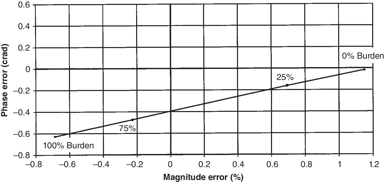
Figure 8.9 Error line corresponding to the VT whose errors appear in Figure 8.8.
8.4.1 Properties of Error Lines
Before we can make full use of error lines it is necessary to understand some of their properties. We begin by plotting an error line for a VT from the magnitude and phase errors measured at two burden points. These are usually either 25% and 100%, or perhaps 0% and 100% of the applicable burden. Let us assume that we have data for the former. We plot the error line from this data, as shown in Figure 8.9.
At this stage, a summary of the important properties of error lines is useful.
- For a particular VT, all the errors corresponding to fractions of a particular burden lie on the same error line.
- The error at any fractional burden is distributed along the error line in direct proportion to the fraction concerned. For example, the errors corresponding to 50% of the rated burden lie half way between the zero burden point and the 100% point.
- The zero burden point can therefore be found by extrapolating the error line to the right of the 25% point, by one third of the distance between the 25% and 100% points. Once the zero burden point (
 has been found, the value of the normalised turns ratio N/Nact can be determined.
 - A unique error line exists for each particular burden power factor. The error line corresponding to a unity power factor burden is known as the base line.
- All error lines for a particular VT must pass through the zero burden point, since this is independent of the burden power factor.
- All error lines for a particular voltage transformer are the same length. Therefore the fractional burden errors from one error line can be easily transferred to another, by scribing arcs of appropriate radii, centred on the zero burden point.
- The error line corresponding to a lagging burden of power factor pf, lags the base line by an angle of arcos(pf ). Thus the error line corresponding to a 0.8 pf burden lags the base line by 36.9°. Therefore once one error line has been plotted, others can be quickly constructed.
The following example will clarify these concepts.
8.4.2 Error Conversion between Burdens of Differing Power Factors
Occasionally it may become necessary to evaluate the magnitude and phase errors at a burden whose power factor is different from that at which it was originally tested. For example, if the error measurements were made with a 0.8 pf burden for a range II, 10 VA VT, which is subsequently to be used as a range I VT, it will be necessary to demonstrate compliance with the IEC standard when burdened at unity power factor. The steps outlined below demonstrate how the unity power factor errors can be graphically obtained from the 0.8 pf results.
Example: We will use the 0.8 pf test data from a 44 kV, Class 0.5, 100 VA VT presented in Table 8.6, to evaluate the errors at unity power factor. (Note that in this instance the test results are independent of the applied voltage over the range 0.8–1.2 pu. This is usually the case.)
Table 8.6 Measured error results from a 44 kV Class 0.5, 100 VA VT (graphed in Figures 8.9 and 8.10).
| Volts (pu) |
Burden (pu) |
Magnitude error (%) | Phase angle (Crad) | ||
| 0.8 pf | 1.0 pf | 0.8 pf | 1.0 pf | ||
| 0.8 | 0.25 | 0.21 | 0.23 | 0.029 | −0.07 |
| 0.8 | 1.00 | −0.23 | −0.14 | 0.058 | −0.30 |
| 1.0 | 0.25 | 0.21 | 0.23 | 0.029 | −0.07 |
| 1.0 | 1.00 | −0.23 | −0.14 | 0.058 | −0.30 |
| 1.2 | 0.25 | 0.21 | 0.23 | 0.029 | −0.07 |
| 1.2 | 1.00 | −0.23 | −0.15 | 0.058 | −0.03 |

Figure 8.10 Error lines for the VT whose error results are shown in Table 8.6. (This illustration is also known as a circle diagram or a fan diagram).
We proceed as follows:
- Step 1: Plot the error line corresponding to the 0.8 power factor data for 25% and 100% burdens. This is the upper line in Figure 8.10.
- Step 2: Determine the zero burden point as described above. In this case, the zero burden error (e0 , γ0) is (0.36%, 0.02 Crad), thus the normalised turns ratio for this VT is 1.0036.
- Step 3: Since the unity pf line leads the 0.8 pf line by an angle equal to arcos(0.8) or 36.9°, this error line can be constructed by simply drawing a line that leads the 0.8 pf line by this angle, passing through the zero burden point (the lower line in Figure 8.10).
- Step 4: All error lines for a given VT have the same length, therefore the 100% error point can be scaled directly from the 0.8 pf line. Errors for any other fractional burden may also be similarly derived.
Since the unity pf error line was used constructed from the 0.8 pf data, the unity pf errors obtained from the graph should be compared with those in the Table 8.6. It can be seen from Figure 8.10 that this IEC 61869‐3 Class 0.5 VT does not quite satisfy the IEEE C57.13 Class 0.3 limits, particularly when a unity power factor burden is applied.
In summary, because of the linear nature of voltage transformers, if two sets of magnitude and phase errors are known for a particular burden, the magnitude and phase errors may be derived for any other burden. This simple graphical process does not require knowledge of any of the VT’s internal parameters, nor does it require complex computations. Annex ZA of IEC 61869‐3 includes a description of this process as well as an equivalent numerical approach to error conversion.
8.5 Re‐rating Voltage Transformers
Occasionally, it may be necessary to re‐rate a VT from its rated class to a higher one. For example, a Class 1 VT may be used in the Class 0.5 over a restricted range of burdens. The error line can be useful in determining the required burden range.
Figure 8.11 shows an example of a VT error line, drawn for a unity pf burden. The IEC 61869‐3 error limits for Class 0.5 instruments are also plotted on this graph. The error line lies within these for burdens between 35% and 79% of the 200 VA rating. Therefore for Class 0.5 operation, the maximum burden permitted is 79% of 200 VA (158 VA) and the minimum burden required is 35% of 200 VA (55.6 VA).

Figure 8.11 Re‐rating a Class 1 VT to Class 0.5 over a restricted range of burdens.
This technique can be very useful when a superior class of VT is required. It is necessary, however, to ensure that the minimum burden calculated for the new class is actually applied to the device.
8.6 Accuracy Classes for Protective Voltage Transformers
The same voltage transformer is frequently used in both metering and protection applications. While the accuracy required for protection need not be as high as that for metering, a protection VT must operate satisfactorily over a considerably wider range of voltages. IEC 61869‐3 defines two accuracy classes for protection VTs, 3P and 6P, shown in Table 8.7. These limits apply from 5% of rated voltage, to the rated voltage multiplied by the applicable voltage factor Fv, over the range of burdens shown in Table 8.3.
Table 8.7 Protective voltage transformer magnitude and phase error limits (IEC 61869‐3).
(IEC 61869‐3 ed.1.0 Copyright © 2011 IEC Geneva, Switzerland. www.iec.ch)
| Protection accuracy class |
Magnitude error (%) |
Phase error | |
| ±Minutes | ±Crad | ||
| 3P | 3 | 120 | 3.5 |
| 6P | 6 | 240 | 7.0 |
It is usual for a VT with a single secondary winding to be assigned both a metering and a protection rating, for example 0.5/3P.
8.6.1 Voltage Factor (Fv)
The voltage factor depends on the magnitude of the over‐voltages that the VT may encounter as a result of faults on or near the bus to which it is connected. The maximum primary voltage that can be supported by a VT can be found by multiplying its rated voltage by the voltage factor Fv. Table 8.8 shows voltage factors for single and three‐phase VTs prescribed by IEC 61869‐3, for both effectively earthed and non‐effectively earthed systems. Together with the Fv values, the table also specifies the duration for which the over‐voltage may exist.
Table 8.8 Rated voltage factors (Fv) for single‐phase inductive VTs.
| Rated voltage factor |
Rated time | Method of connecting the primary winding and system earthing conditions |
| 1.2 | Continuous | Between phases in any network Between transformer star‐point and earth in any network |
| 1.2 | Continuous | Between phase and earth in an effectively earthed neutral system (IEC 61869–1: 2007, 3.2.7a) |
| 1.5 | 30 s | |
| 1.2 | Continuous | Between phase and earth in a non‐effectively earthed neutral system (IEC 61869–1: 2007, 3.2.7b) with automatic earth fault tripping |
| 1.9 | 30 s | |
| 1.2 | Continuous | Between phase and earth in an isolated neutral system (IEC 61869–1: 2007, 3.2.4) without automatic earth fault tripping or in a resonant earthed system (IEC 61869–1: 2007, 3.2.5) without automatic earth fault tripping |
| 1.9 | 8 h |
(IEC 61869‐3 ed.1.0 Copyright © 2011 IEC Geneva, Switzerland. www.iec.ch)
Note 1. The highest continuous operating voltage of an inductive voltage transformer is equal to the highest voltage for the equipment (divided by ![]() for transformers connected between a phase of a three‐phase system and earth) or the rated primary voltage divided by the factor 1.2, whichever is the lower.
for transformers connected between a phase of a three‐phase system and earth) or the rated primary voltage divided by the factor 1.2, whichever is the lower.
Note 2. Reduced rated times are permissible by agreement between manufacturer and purchaser.
Voltage factors vary between 1.2 and 1.9 and are determined largely by the performance of the earthing system at the location of the VT in question. A voltage factor of 1.9 requires that the VT be capable of supporting almost twice its rated voltage. It must therefore be conservatively designed to operate at a relatively low flux density at its nominal voltage and be equipped with sufficient insulation to cope with the required over‐voltage.
8.6.2 Earth Fault Factor and Effective Earthing
Put simply, the earth fault factor is the ratio of the highest phase to earth voltage on a healthy phase during an earth fault on a system, to the magnitude of the same voltage in the absence of such a fault.
The earth fault factor has a direct impact on the potential that voltage transformers must support near to a fault. It quantifies the maximum in potential experienced by the healthy phase(s) during fault conditions. The earthing system at the fault location is classified as either effectively earthed or non‐effectively earthed, according to the magnitude of the earth fault factor.
A three‐phase earthed neutral system is said to be effectively earthed at a given location, if the earth fault factor at that location does not exceed 1.4. On the other hand, a system is said to be non‐effectively earthed if the earth fault factor there exceeds 1.4.
The earth fault factor depends on the system impedances at the fault, and it can be shown that a system can be considered effectively earthed if the ratio of resistive component of the zero‐sequence impedance R0, to the positive sequence reactance X1, is less than one, and the ratio of the zero‐sequence reactance X0, to the positive sequence reactance X1, is less than three.
The over‐voltage problem occurs during faults to earth, when a potential difference arises between the neutral terminal of the supply transformer and the star point of the VT in question. This neutral shift voltage occurs as a result of the fault current flowing through an impedance between these points. This may be the resistance between the ground connections of the supply transformer and the star point of the VT, the impedance of the neutral conductor in MV systems when the neutral is distributed, or the impedance of the neutral connection where impedance earthing is used.
The potential difference between these terminals is generally small, and can usually be neglected. However, during earth faults, where substantial ground currents can flow, this potential may become significant. If the VT in question is near a phase‐to‐ground fault, the resulting potential rise appears as a neutral shift voltage, causing a reduction in the potential seen by the faulted phase, and an increase in the potential seen by at least one other.
This is illustrated in Figure 8.12, where a phase‐to‐ground fault near the VT causes a substantial rise in the local earth potential. In this case, it is assumed that the earth resistance between the remote earth and that of the supply transformer is dominant, and therefore most of the faulted phase potential is dropped between the two ground connections. As a result, the neutral potential at the VT rises, reducing the A phase voltage in proportion, and increasing both the B and C phase voltages seen by the VT.

Figure 8.12 Neutral shift voltage resulting from an earth fault.
If the earth fault factor at a particular location is 1.4 or less, then allowing for bus voltages of up to 1.1 pu, the maximum phase potential seen by a VT at that location under fault conditions, will be equal to ![]() . Therefore a voltage factor of 1.5 is appropriate.
. Therefore a voltage factor of 1.5 is appropriate.
The largest earth fault factor possible is ![]() , occurring when a phase‐to‐ground fault occurs at the VT and faulted phase potential is therefore zero. If the maximum bus voltage is 1.1 pu, then the voltage factor will be
, occurring when a phase‐to‐ground fault occurs at the VT and faulted phase potential is therefore zero. If the maximum bus voltage is 1.1 pu, then the voltage factor will be ![]() .
.
The duration associated with the voltage factor depends on the operating time of the earth fault protection equipment. In some cases, such as resonant or impedance earthing, the fault may exist for some time before being cleared, and therefore the VT may need to have a continuous over‐voltage capability. In other cases, the fault will be cleared relatively quickly, and the VT need only be short term over‐voltage rated.
8.6.3 IEEE C57.13 Over‐Voltage Ratings
IEEE C57.13 defines five groups of voltage transformers each with over‐voltage and exposure durations ratings, shown in Table 8.9.
Table 8.9 IEEE Over‐voltage limits.
(Adapted and reprinted with permission from IEEE. Copyright IEEE C57.13 (2008) All rights reserved. Permission for further use of this material must be obtained from IEEE. Requests may be sent to stds‐[email protected]).
| Group | Intended primary connection | Over‐voltage factor | Duration |
| 1 | Line to line or line to ground |
1.25 | 8 hours (@ 64% of the thermal burden) |
| 2 | Line to line | 1.1 | Continuous |
| 3 | Line to ground | √3 | 1 minute |
| 4a | Line to ground | 1.25 | 8 hours (@ 64% of the thermal burden) |
| 5 | Line to ground | 1.4 | 1 minute |
8.7 Dual‐Wound Voltage Transformers
Recent years have seen a move towards the use of single‐phase VTs with two secondary windings. Occasionally one winding is designated for metering and the other for protection, but more commonly, both are rated for either metering or protection duties (for example a dual 0.5/3P rating). However, this does not mean that all windings are so rated, and care must be taken to ensure that metering circuits are supplied appropriately. Dual‐wound VTs provide a degree of flexibility where both revenue and check meters are required to be supplied from separate VT windings. It also allows for the segregation of protection and metering circuits should this be required.
The presence of two secondary windings fed from a common primary, means that the burden on one secondary will affect the errors associated with the other. Provided that both windings are equally burdened, a dual‐wound VT can be treated as a single winding device from the point of view of magnitude and phase errors. While this is rarely the case, modern protection and metering systems generally impose very light burdens on VTs, and a small imbalance in burden between windings may be insignificant.
Under IEC 61869‐3 the rated burden applies to each secondary winding. Error testing is therefore usually carried out when both windings are burdened at 25% and 100% of their rating. On the other hand, the burden defined under IEEE C57.13 is the total burden that can be applied to both windings. Therefore VTs must be class compliant when this burden is apportioned in any ratio between the secondary windings.
8.8 Earthing and Protection of Voltage Transformers
Star‐star connected VTs are generally only used in solidly grounded networks where a low zero‐sequence impedance exists between the VT star point and the supply neutral. This permits the third harmonic component of the VT’s magnetising current (a zero‐sequence current) to flow, and thus allows the flux in the VT to achieve its correct value. Without this current, the flux waveform will be a little flat‐topped, and an erroneous third harmonic component will be present in each phase voltage, sufficient to corrupt energy metering and power quality measurements, both of which require an accurate representation of the phase voltages. This makes the use of conventional three‐element metering impractical in ungrounded three wire circuits.
Fortunately, the line voltages reported by star connected VTs are not similarly corrupted (since the zero‐sequence voltage component cancels in the subtraction of phase potentials), and therefore this configuration can be used in applications where only line voltage information is required. However, it is more likely that line connected VTs will be used in ungrounded networks.
Where single‐phase star connected VTs are applied to ungrounded networks, it is necessary to ensure that the voltage rating of each is equal to the maximum rated line voltage of the network. This is because a phase‐to‐ground fault may exist for some time before being cleared.
8.8.1 Ferro‐Resonance
There is a danger of exciting a ferro‐resonant oscillation when VTs are connected between line and ground on ungrounded networks or networks grounded through a high impedance. As explained in Chapter 11, ungrounded networks tend to be loosely tied to ground through the action of the parasitic capacitances that exist between each phase and ground, as depicted in Figure 8.13. Because there is no firm ground connection, the source phase voltages can vary with respect to ground in response to a disturbance such as ferro‐resonance.

Figure 8.13 Ungrounded network.
Ferro‐resonance is a highly non‐linear oscillation that arises between the magnetising inductance of a transformer and the stray system capacitance existing in parallel with it. It can be triggered by a temporary over‐voltage, possibly as a result of a switching transient, which drives the transformer deep into the saturated region of its magnetising characteristic. The large magnetising currents that result can generate very high oscillatory voltages, across a range of frequencies, both above and below the system frequency, due to the non‐linear nature of the transformer’s magnetising inductance. This may result in the destruction of the VT and possible damage to nearby equipment.
As with any resonant condition, the amplitude of a ferro‐resonant oscillation is influenced by the degree of damping present, and therefore a resistive burden on the VT can play an important role in suppressing ferro‐resonance. In cases where star connected VTs are used on ungrounded networks, a sufficiently resistive burden must be applied to avoid the possibility of ferro‐resonance. This may impose a significant thermal burden on a VT, beyond that permitted for metering purposes. Therefore in addition to the reasons cited above, this connection will generally only be used for residual voltage (ground fault) detection.
8.8.2 Ferro‐Resonance in Capacitive VTs
While all VTs are subject to ferro‐resonance in adverse circumstances, capacitive VTs are slightly more so, given that they already contain both capacitive and inductive elements. In order to prevent sustained ferro‐resonance, damping components are generally included in parallel with the secondary winding, as shown in Figure 8.14. The damping system chosen should not load the VT excessively at the fundamental frequency, since this will reduce its available VA capacity. Circuits like that shown in Figure 8.14a are often used in the secondary circuit of the inductive voltage transformer. Here a low impedance resistive path exists across the secondary winding at frequencies away from the system frequency. Since ferro‐resonance usually generates energy at many harmonic frequencies, the damping so provided will help to reduce the oscillation. Figure 8.14b shows an alternative arrangement where a spark gap connected resistor is connected across the VT secondary. This will consume no energy under normal circumstances, but will provide damping when the gap breaks down under high voltage conditions. This circuit also includes a saturable inductor L which will present a low impedance when saturated by large secondary voltages.

Figure 8.14 (a) CVT off frequency damping (b) CVT spark gap, saturable inductor damping.
In addition to these techniques, non‐linear devices such as metal oxide varistors (MOVs) are also used as damping elements. These devices are made from a crystalline zinc oxide structure, the crystal boundaries of which form p‐n junctions that pass very little current under low voltage conditions. At high applied voltages these junctions break down in an avalanche mode, and the device impedance falls to a low value. However, they can only dissipate a certain amount of energy before permanent damage occurs, and therefore the energy rating should be carefully matched to the intended application.
IEC 61869‐5 deals with capacitive voltage transformers, and specifies that for any burden up to the device rating that once triggered, a ferro resonance condition shall not be sustained. This is generally satisfied by the provision of adequate damping of the types described above. This standard defines a maximum instantaneous error ![]() , defined by:
, defined by:

where ![]() is the maximum instantaneous error,
is the maximum instantaneous error, ![]() is the peak secondary voltage, UP is the primary voltage (r.m.s), UPr is the rated primary voltage (r.m.s), kR is the transformation ratio and TF is the duration of ferro‐resonance (seconds).
is the peak secondary voltage, UP is the primary voltage (r.m.s), UPr is the rated primary voltage (r.m.s), kR is the transformation ratio and TF is the duration of ferro‐resonance (seconds).
The maximum instantaneous error ![]() , shall fall to a value less than 10% after the duration TF, as defined in Tables 8.10 and 8.11. Note that it is possible that the effects of ferro‐resonance may have entirely disappeared by time TF, or that the oscillation may still be decaying. In either event the value of
, shall fall to a value less than 10% after the duration TF, as defined in Tables 8.10 and 8.11. Note that it is possible that the effects of ferro‐resonance may have entirely disappeared by time TF, or that the oscillation may still be decaying. In either event the value of ![]() shall be less that 10%.
shall be less that 10%.
Table 8.10 Ferro‐resonance requirements for effectively earthed CVTs.
(IEC 61869‐5 ed.1.0 Copyright © 2012 IEC Geneva, Switzerland. www.iec.ch)
| Primary voltage UP | Ferro‐resonance oscillation duration TF (Seconds) | Error ε^F (%) after duration TF |
| 0.8 UPr | ≤0.5 | ≤10 |
| 1.0 UPr | ≤0.5 | ≤10 |
| 1.2 UPr | ≤0.5 | ≤10 |
| 1.5 UPr | ≤2.0 | ≤10 |
Table 8.11 Ferro‐resonance requirements for non‐effectively earthed CVTs (isolated neutral).
(IEC 61869‐5 ed.1.0 Copyright © 2012 IEC Geneva, Switzerland. www.iec.ch)
| Primary voltage UP | Ferro‐resonance oscillation duration TF (Seconds) | Error ε^F (%) after duration TF |
| 0.8 UPr | ≤0.5 | ≤10 |
| 1.0 UPr | ≤0.5 | ≤10 |
| 1.2 UPr | ≤0.5 | ≤10 |
| 1.9 UPr | ≤2.0 | ≤10 |
8.8.3 Earthing the LV Star Point
The LV star point should always be earthed, although this is more for reasons of safety. If the secondary star point was permitted to float, then it is possible that a substantial voltage could develop between the secondary star point and ground. This occurs because of the capacitive coupling between each HV winding and the associated LV winding, and between the each LV winding and ground, as is illustrated in Figure 8.15.

Figure 8.15 Capacitive coupling between windings and ground in a voltage transformer.
Provided that corresponding capacitances are equal, the secondary star point will remain close to ground potential, but if there is a mismatch between these capacitances then a neutral shift voltage will be generated which may pose a safety risk to both personnel and equipment. For this reason, the LV star point must be earthed so that such a potential cannot exist.
In the case of line connected VTs, where the secondary windings have no star point, it is customary to ground the white phase terminal, for the same reasons.
8.8.4 VT Protection
Voltage transformers are expensive and deserve some degree of protection, on both the primary side and the secondary side. Primary fusing is normally selected to protect the VT in the event of internal faults or short circuits close to the secondary terminals. It should be capable of carrying the inrush current of the device without causing nuisance tripping. Similarly, secondary fusing or magnetic circuit breakers should also be provided to protect the secondary from downstream faults and to provide a convenient method of isolating the VT. It is always preferable for the secondary protection to operate before the primary fuse, and therefore the secondary protection should be chosen accordingly.
Figure 8.16 shows what can go wrong when a VT fails internally, where the fault is not cleared by a primary fuse. The right‐hand VT in the figure shows a solid copper connection to the HV terminal; this link would normally be replaced with an HV fuse. In this case the left‐hand VT failed internally, and since it was not fuse protected the fault progressed to the stage where carbon condensate damage occurred throughout the cubicle in which it was housed. Where a VT is connected to an incoming feeder, such a fault can only be cleared by tripping the associated circuit breaker or by a bus zone protection operation, neither of which is desirable.

Figure 8.16 VT failure – note the lack of HV fusing, the thermal damage to the left‐hand VT and the carbon condensate damage throughout the cubicle.
8.9 Non‐Conventional Voltage Transformers
Both inductive and capacitive voltage transformers exhibit a non‐linear frequency response which severely limits their usefulness in measuring harmonic voltages. Capacitive VTs are tuned to the fundamental frequency and therefore their performance is only guaranteed over a very narrow bandwidth. Inductive VTs also suffer from non‐linear effects in the frequency domain due to the existence of parasitic winding and inter‐winding capacitances. These create resonances in the frequency response, leading to large errors in the apparent turns ratio. Because HV VTs require more turns on the primary winding than do MV VTs, they are subject to larger parasitic capacitances and, as a result, the first resonance usually occurs at lower frequencies, further restricting their use for harmonic measurement.
Non‐conventional voltage transformers have been developed for power quality applications as well as for use in gas insulated switchgear (GIS). These devices are generally either based on the principle of a voltage divider or on a fibre optic material sensitive to the electric field associated with the potential to be measured. Resistive divider networks may be used to produce a scaled version of the measured voltage, but the effects of stray capacitance limit the device response at high frequencies. The potential divider shown in Figure 8.17a contains both resistive and capacitive elements connected in parallel and provided that ![]() then linear performance can be achieved to frequencies in excess of 10 kHz, making it applicable to broadband harmonic measurements.
then linear performance can be achieved to frequencies in excess of 10 kHz, making it applicable to broadband harmonic measurements.

Figure 8.17 (a) RC voltage divider sensor (b) RC differential voltage sensor.
The simple CR divider circuit shown in Figure 8.17b is used in some GIS switchgear and provides an output voltage proportional to the derivative of the input voltage, which must be amplified and integrated to reconstruct the input voltage. Since these circuits are incapable of driving any appreciable burden, the associated amplifier circuitry must also perform this function. Modern electronic protection relays and control equipment present very little burden and therefore it is quite practical to provide a low power analogue replica of the measured voltage. However, these instruments may also be configured to provide digital information to the substation secondary equipment over a fibre optic link. This approach is usually adopted in the case of fibre optic voltage sensors.
The IEC standard IEC 61850‐6 describes a digital interface between field based current and voltage transformers and the associated control room instrumentation. Under this standard, current and voltage information from either conventional or non‐conventional instrument transformers (NCITs) is digitised and time synchronised in the field by a merging unit, and conveyed optically to the associated protection and control equipment within the substation. This approach has three significant advantages: firstly, it greatly simplifies the wiring required and entirely removes the effects of cabling and equipment burdens; secondly multiple items of secondary equipment may be connected to the same instrument transformers, and where non‐conventional instrument transformers are fitted, these may be generic and not application specific, thus simplifying the design and specification of the primary equipment. Finally, non‐conventional voltage transformers do not suffer from the effects of ferro‐resonance. For all these reasons, it is likely that many more NCITs will find application in the future.
8.10 Problems
- Apply Equation (6.2) to the CVT circuit shown in Figure 8.18, and show that the power delivered by a CVT is given by
 . Hence determine the phase shift (δ) that will occur in V2, with respect to the voltage at V1. Will V2 lag or lead V1? Assume that the intermediate transformer is lossless and that all the power is therefore consumed by the burden resistance.
(Answer: +1.8°)

Figure 8.18 Diagram for question 1. (C1 = 0.0192 μF, C2 = 0.078 μF, V1 = 110 kV/√3, f = 50 Hz, the output voltage is 110v/√3 and rated burden of the CVT is 150 VA).
- Calculate the value of the tuning inductance L in question 1. Assuming that the transformer is ideal, find the maximum steady state current that this component must carry.
(Answer: 104.35H, 12 mA)
- Calculate the phase shift that you expect between V2 and the transformer output terminals in the schematic above, and hence determine the overall phase shift between V1 and the output, under the assumptions made above.
(Answer: −1.8°, 0°)
- The intermediate transformer in question 1 has a short‐circuit impedance of 0.12 + j0.2 ohms and a normalised turns ratio of 1.004. The tuning inductance has a Q value of 20 at the fundamental frequency. Determine the magnitude and phase errors of this CVT when fully burdened: (a) at 50 Hz at 0.8 pf and (b) at 150 Hz.
(Answers: 50 Hz: e = −0.76%, γ = −0.23 Crad; 150 Hz: e = −2.13% γ = 8.3 Crad.)
- An 11 kV/√3:110v/√3, 50 VA inductive VT has the magnitude and phase errors shown in Table 8.12 when burdened at 0.8 power factor. Find the short‐circuit impedance of this device and its corresponding short‐circuit current, assuming negligible impedance on the primary side. What size primary and secondary fuses would you consider using to protect this VT, and why?
(Answers: r = 0.39 Ω, x = 0.16 ohms. Isc = 151 A, HV fuse rating
 , LV fuse rating
  )
)Table 8.12 VT error information.
0.8 pf burden (%) Ratio correction factor Phase error (Crad) 0 0.997 0.02 100 1.002 0.15 - Does the VT in question 5 comply with the 0.3 Class limits as defined under C57.13?
If not, at what burden would it comply?
(Answers: Not with a 0.8 pf burden, 43 VA)
- A 22 kV VT is installed at a location remote from its associated supply transformer. If the positive, negative and zero‐sequence impedances at this location are shown in Table 8.13, calculate the earth fault factor at this location for a phase‐to‐ground fault close to the VT. Is this VT effectively earthed or non‐effectively earthed? How would this change if
 ?
?
Table 8.13 Impedance information.
Positive and negative sequence impedance
(R1 = R2 ≈ 0)Total zero‐sequence impedance Ground resistance from VT location to the supply transformer neutral 


(Answer: ≈1.4)
- A Class 0.3 VT has the magnitude and phase errors given in Table 8.14, for a resistive burden. Plot these errors for this VT at 100% burden as a function of the burden power factor, and hence show that the phase error is slightly more sensitive to the power factor than the magnitude error. Your graphs should resemble those in Figure 8.19. (Note that the shape of these graphs depends to a large extent on the actual characteristics of the VT in question.)
Table 8.14 VT error information.
% burden Magnitude error (%) Phase error (Crad) 0 0.272 0.00 100 −0.016 −0.16 
Figure 8.19 Variation of magnitude and phase errors with burden power factor.
How would you expect the errors to behave if this VT were to be burdened with a progressively more capacitive load?
8.11 Sources
- 1 IEC International Standard 61869‐3, 2011. Instrument transformers Part 3: Additional requirements for inductive voltage transformers. International Electrotechnical Commission, Geneva.
- 2 IEC International Standard 61869‐5, 2012. Instrument transformers Part 5: Additional requirements for capacitor voltage transformers. International Electrotechnical Commission, Geneva.
- 3 IEEE Standard C57.13, 2008. IEEE standard requirements for instrument transformers. IEEE Power Engineering Society, New York.
- 4 IEEE Standard C57.13.6, 2005. IEEE standard for high accuracy instrument transformers. IEEE Power Engineering Society, New York.
- 5 Australian Standard AS1243, 1982. Voltage transformers for measurement and protection. Standards Australia: Sydney.
- 6 ABB Inc. Instrument transformers, technical information and application guide. Pinetops, NC 27864, USA.
- 7 General Electric Company. ‘Manual of instrument transformers’. Meter & Instrument Business Dept, Somersworth, N.H. 03878, USA.
- 8 Areva. Network Protection and Application Guide, 2005. Areva, Paris.
- 9 IEC/TR 61850–1 Ed. 2.0: Communication networks and systems for power utility automation – Part 1: Introduction and overview, 2013, International Electrotechnical Commission, Geneva.
- 10 Reza Tajali PE. Line to ground voltage monitoring on ungrounded and impedance grounded power systems. Square D Company, Power Systems Engineering Group LaVergne. Tennessee 37086.
- 11 Fuchsle D, Stanek M. Experiences with non‐conventional instrument transformers (NCITs), ABB High Voltage Products, Switzerland.