
14
Operational Aspects of Power Engineering
In this chapter we examine some of the operational issues that practising engineers encounter every day, with a view to providing the new engineer with an introduction to some of the more important items. The material presented includes a discussion of the different bus arrangements and switchgear used in AC networks, electrical safety from the point of view of both electric shock and arc flash injury, limits of approach as well as isolation and switching procedures. Familiarity with these will assist in a more rapid integration into the profession. We begin with a discussion of device numbers and a description of the one line diagram.
14.1 Device Numbers
In chapter 12 symbols were used in some illustrations to identify protection relays. In addition to these symbols (defined in IEC 60617‐ Part 7), device numbers and acronyms are also defined in IEEE Standard C37.2 where they provide a shorthand notation for the function of devices installed in electrical installations. While most relate to electrical functions, some mechanical functions such as flow and pressure switches are also included.
Historically each device number represented an individual item of equipment, such as protection relays. Today they also apply to particular protection functions generated by the hardware or software contained in a multi‐function relay. Device numbers are often preceded by a numerical prefix which may indicate a particular unit in a multiple unit installation and/or the potential of the bus concerned. For example, device number 52 applies to circuit breakers, and in a substation with three identical transformers the associated breakers may be identified by an alphabetic prefix A, B or C. In addition, circuit breakers on the HV side of a transformer frequently carry a 1 prefix and therefore are labelled A152, B152 and C152. Those on the LV side are often prefixed by 2 and appear as A252, B252 and C252. Prefixes may extend to other potentials as well; therefore 352 or 452 will signify circuit breakers operating at progressively lower potentials. Any device number may include prefixes.
Similarly, a suffix can also be added to a device number to further define its application. An inverse time overcurrent relay, for example, has the device number 51. A suffix G (51G) implies that it is connected to a current transformer in the ground circuit of the device it is protecting; it therefore provides an inverse ground fault overcurrent function. (An alternate suffix N (neutral) is used in cases where the relay is connected to a residual source of current or voltage for the same purpose.) Suffixes are also frequently used to identify multiple devices operating at the same potential. In some countries, current transformers use the device number 96, so multiple current transformers all associated with the HV windings of transformer A in the example above would be identified as A196A, A196B and A196C.
Device numbers and also acronyms are used in drawings and technical documents. They also frequently appear in the labelling used to identify the equipment itself. Tables 14.1 and 14.2 include some of the more common device numbers and acronyms defined in IEEE C37.2, together with the equivalent symbols defined in the IEC standard IEC 60617.
Table 14.1 Common IEEE C37.2 device numbers and their IEC 60617 equivalent symbols.
(Adapted and reprinted with permission from IEEE. Copyright IEEE C57.2 (2008). All rights reserved. Permission for further use of this material must be obtained from IEEE. Requests may be sent to stds‐[email protected]) (IEC 60617–7 (1996) Copyright © 1996 IEC Geneva, Switzerland. www.iec.ch)
| Device number (IEEE C37.2) |
Symbol (IEC 60617 – Part 7) |
Description |
| 21 | Z < | Impedance relay (distance relay) |
| 24 | U/f > | Over excitation relay (over fluxing, volts/Hz) |
| 27 | U < | Under voltage relay |
| 29 | — | Disconnector or isolation device |
| 40 | — | Loss of excitation |
| 46 | I2 > | Negative sequence current relay |
| 47 | U2 > | Negative sequence voltage relay |
| 50 | I ≫ | Instantaneous overcurrent relay |
| 50N | I0 ≫ | Instantaneous ground fault relay |
| 51 | I > | Inverse time overcurrent relay |
| 51G | I0 > | Inverse time ground fault relay |
| 52 | — | AC circuit breaker |
| 152 | — | Primary side circuit breaker |
| 252 | — | Secondary side circuit breaker |
| 55 | Cos ϕ > | Power factor relay |
| 59 | U > | Over voltage relay |
| 64 | I0 > | Ground fault relay |
| 67 | I > | Directional overcurrent fault relay |
| 67N | I0 > | Directional ground fault relay |
| 68 | I2 > | Transformer inrush blocking relay |
| 78 | ϕ > | Phase angle relay |
| 81R | df/dt | Rate of change of frequency |
| 81U | f < | Under‐frequency relay |
| 81O | f > | Over‐frequency relay |
| 87 | ΔI > | Differential relay |
| 96 | — | Current transformer (some countries only) |
| 97 | — | Voltage transformer (some countries only) |
| 99 | — | Multi function relay (some countries only) |
Table 14.2 Common acronyms defined in IEEE C37.2.
(Adapted and reprinted with permission from IEEE. Copyright IEEE C57.2 (2008). All rights reserved. Permission for further use of this material must be obtained from IEEE. Requests may be sent to stds‐[email protected])
| Acronym | Description |
| AFD | Arc flash detector |
| CLK | GPS clock |
| DDR | Dynamic disturbance recorder |
| DFR | Digital fault recorder |
| ENV | Environmental data recorder (wind, temp, icing, etc.) |
| HIZ | High impedance ground fault detector |
| HST | Historian (data gathering equip, for trend analysis) |
| LGC | Logic scheme (programmed protection, remedial action etc.) |
| MET | Substation metering equipment (W, VAr, VA, PF, energy) |
| PMC | Phasor data concentrator |
| PMU | Phasor measurement unit |
| PQM | Power quality measurement unit (harmonics and disturbances) |
| RIO | Remote input/output device |
| RTU | Remote terminal unit / data concentrator |
| SER | Sequence of events recorder (SOE) (fault data recording) |
| TCM | Trip circuit monitor (trip circuit supervision, TCS) |
14.2 One Line Diagram (OLD)
The one line diagram (also called a single line diagram SLD) is a convenient way of providing a concise overview of part or all of a power system; indeed, we have already seen simple one line diagrams in many of the proceeding chapters. They show only one phase and are usually drawn so that the highest potential appears at the top, while lower potentials and individual loads appear towards the bottom of the drawing. The one line diagram contains a representation of all the primary equipment such as transformers, circuit breakers, disconnectors, busbars, voltage and current transformers, as well as the secondary equipment comprising associated protection relays, energy metering, monitoring, control and communications equipment. It does not show the detailed wiring between these elements, but it does indicate the general interconnections between primary and secondary equipment, for example, which CTs and VTs supply particular protection relays or energy meters. Protection functions are represented in terms of the relevant device number, symbol or acronym.
The one line diagram also generally includes the voltage, current and VA ratings of all items of primary equipment and thus it provides a concise graphical description of the electrical installation at a particular site. Because of this, it is also used as a convenient data input method by network analysis programs for fault level and load flow studies. It is also one of the first documents used in planning maintenance activities and in fault finding, and should be kept up to date as system changes occur.
By way of example, Figure 14.1 shows the one line diagram of a small hydro generation station. The generator operates at 3.3 kV, delivering up to 5.1 MW into the local 33 kV network via a star‐delta step‐up transformer and a dedicated aerial feeder. The drawing shows all the primary and secondary equipment as well as the associated protection relays and energy metering.

Figure 14.1 One Line Diagram of a small hydro generating station.
The generator is a star connected machine with its neutral terminal cable connected to a 380 ohm neutral earthing resistor (NER), dimensioned to avoid serious winding damage in the event of a stator earth fault. The delta star transformer T1 takes the machine potential to 33 kV for connection to the local distribution network. Machine breaker A52 is located on the transformer’s HV side, the HV star point being grounded through circuit breaker B52 only when the machine operates in island mode supplying the local area while isolated from the remainder of the grid. At all other times the neutral ground reference is provided from the remote 33 kV substation. Isolator A29 permits the machine to be removed from the grid for maintenance purposes while the station continues to be supplied via the station service transformer.
Duplicate A & B primary protection is provided for the machine and the machine/ transformer combination by two numerical Schweitzer SEL‐700G generator protection relays. The A protection relay A99A, provides fast differential protection across the machine windings using CTs A96A and A96D, and impedance and overcurrent protection using A96A. It also provides over‐excitation, under/over voltage and frequency, reverse power and loss of excitation protection from voltage information provided by voltage transformer A97B. This relay includes an automatic synchronisation package that compares the machine voltage and frequency to that of the network, sending signals to both the auto voltage regulator (AVR) and the governor to permit the machine to be synchronised without operator intervention.
The duplicate protection relay A99B also provides these protection functions from the 33 kV bus, while providing differential machine and transformer protection by comparing the machine winding current with that delivered by the outgoing aerial feeder. The relay applies the necessary current scaling and phase shifting through software, avoiding the need for complex CT connections. Duplicate transformer HV earth fault protection (50G) is provided by CTs A196D and A196E. Both relays also include stator fault protection by detecting the potential developed across the NER via VT A97A. Each also records watt, VAr, voltage and current information for system control and data acquisition (SCADA) purposes.
The outgoing 33 kV aerial feeder is separately protected by a Schweitzer SEL311L feeder protection relay, which provides differential, distance and overcurrent protection. In this case an optical communications link provides current comparison between the relays at each end of the feeder. Finally current and voltage transformers A196C and A197B provide an energy meter with information relating to the net energy delivered to the feeder. All the above information is readily available from the one line diagram, demonstrating its usefulness in summarising the essential characteristics of a network.
14.3 Switchgear Topologies
We shall investigate several of the more common MV and HV bus arrangements, but first we begin with a brief discussion of the insulating media used in MV and HV switchgear. Traditionally, air has been used to provide dielectric insulation between busbars and conductors in HV and EHV outdoor aerial switchyards. However, the large clearances required demand a sizeable footprint, which can present a problem where space is limited. Figure 14.2 shows part of a large urban substation occupying several hectares. Such a substation should ideally be located very close to the load centre it serves, but the land requirement frequently means that a compromise must be made, often leading to longer than desirable distribution feeders.

Figure 14.2 Part of an urban aerial switchyard.
Circuit breakers used in aerial switchyards are generally classified as dead tank or live tank. As the name suggests, the interruption chambers of a dead tank breaker are at ground potential, with each current interrupter being contained within its own ‘tank’, as shown in Figure 14.3a. The HV terminations are made via bushings around which are positioned the necessary current transformers. Live tank breakers on the other hand, use bushing‐like interruption chambers and operate at phase potential with respect to ground. They do not have provision for current transformers, which must be provided separately. Because both these circuit breakers periodically require maintenance, it is customary to install an isolation switch (or disconnector) on the supply side, in order to permit the breaker to be earthed while maintenance activities are carried out. An isolation switch also provides a visual indication of disconnection.
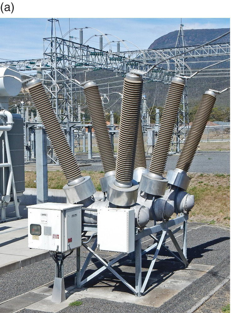

Figure 14.3 (a) 220 kV Dead tank circuit breaker (b) Live‐tank circuit breakers (left) and associated current transformers (right).
In the 1970s gas insulated switchgear (GIS) became commercially available as an alternative to aerial switchyards, and while it is considerably more compact, it is also more expensive. This mainly indoor technology uses sulphur‐hexafluoride gas (SF6) to insulate the busbars and to provide the necessary arc quenching in circuit breakers. Because of its extremely good insulating properties, the phase‐to‐phase and phase‐to‐ground clearances are very much smaller than those required in air. This provides for very compact equipment, in which both the busbars and the associated switchgear are enclosed in a heavy metallic casing, sufficient to contain the gas pressure and, more importantly, the effects of a fault. Figure 14.4 shows a suite of 145 kV double bus GIS switchgear in which the busbars are contained within the circular chambers running the length of the suite.

Figure 14.4 Double bus 145 kV GIS switchgear.
GIS technology finds application in city and urban areas where space is at a premium. It can also be used to advantage in the upgrading of older aerial switchyards, where the limited space makes it difficult to build a new switchyard within an operating old one. A suite of GIS switchgear can often be installed in a vacant section of a yard, allowing circuits to be progressively transferred from old to new, with minimal load disruption.
SF6 is a particularly potent greenhouse gas, and manufacturers are now mixing it with other gasses to reduce the possible impact on the environment should it escape. As environmental concerns about the ongoing use of SF6 grow, manufacturers are also turning to other gases for arc quenching and dielectric insulation duties. Carbon dioxide is finding application in MV and HV circuit breakers as a quenching medium, and although it too is a greenhouse gas, it is much less environmentally damaging than SF6. As part of this trend, vacuum circuit breaker technology, which has been widely used up to 52 kV, is now being investigated for use at higher potentials.
Indoor MV metal enclosed switchgear (also called metal clad switchgear) uses air to insulate the internal busbars. It consists of a series of abutting cubicles, one for each of the incoming and outgoing circuits, through which pass the AC busbars (see Figure 14.8b). Connection is made between the busbars and an outgoing circuit when the associated breaker is racked onto the busbars and closed. The circuit breaker contacts mate with the busbar stubs, connecting the circuit side to the bus through the breaker. Isolation is achieved when the circuit breaker is opened and racked off the busbars. As a result, metal clad switchgear does not require the isolation switches necessary in aerial switchyards.
Figure 14.5 shows an 11 kV vacuum switch temporarily mounted on a trolley enabling it to be withdrawn from its cubicle. The right‐hand photo shows the circuit breaker spring‐loaded ‘fingers’ that make electrical contact with the busbar stubs.

Figure 14.5 Left: A single bus 11 kV vacuum circuit breaker, withdrawn from its cubicle. Right: Circuit breaker: busbar contacts (foreground), vacuum interruption canisters (background).
Last century, transformer oil was commonly used as an insulating medium in MV circuit breakers due to its excellent arc quenching properties, and many oil insulated switches are still providing good service. However, over time, oil becomes contaminated with carbon and combustible gasses such as acetylene and ethylene, and it must be periodically replaced, imposing an ongoing maintenance requirement. Because of this and the risk of fire, oil is no longer preferred. Modern MV circuit breakers generally use either a vacuum or SF6 gas, while HV breakers generally use SF6 as the quenching medium.
14.3.1 Common Busbar Configurations
There are numerous ways in which incoming feeders and the loads they supply can be configured on a busbar. Some arrangements, while more expensive, offer more load security and operational flexibility than others. It is generally the importance of the load that dictates the choice of bus configuration.
Non‐critical loads, for example, may be supplied from a simple single bus arrangement, like that shown in Figure 14.6. This provides very little operational flexibility and in the unlikely event of a bus fault all load will be lost. Critical loads on the other hand, are usually provided with a degree of supply redundancy. Typically this may include duplicate incomers from separate transformers, feeding the load from two independent bus sections, so that a fault on one will not result in a loss of load from the other.

Figure 14.6 Single bus arrangement.
Operational flexibility should also be considered. For example, is it possible to remove circuit breakers or protection relays for maintenance, without disturbing the load? Load segregation is also important in the case of critical loads, which are often fed from a different bus section to non‐critical load. This removes the possibility of critical load loss due to a fault in a piece of non‐critical equipment. All these items should be considered when choosing a particular bus configuration.
Single Bus Configuration
The simplest configuration is the single bus arrangement shown in Figure 14.6, drawn to represent an HV aerial bus where each circuit breaker is provided with the isolation switches necessary to permit circuit breaker maintenance. While this is the least expensive arrangement, as mentioned above, it suffers from the distinct disadvantage that a bus fault will lead to the loss of the entire bus. Individual circuits must also be removed from service in order to maintain the associated circuit breaker or the protection relay. On the other hand, this configuration is easy to operate and expand, while bus zone and feeder protection is straightforward to implement.
Sectionalised Bus
Figure 14.7 shows a modification to the HV single bus arrangement with the inclusion of a bus‐coupler circuit breaker and its associated isolation switches. A sectionalised bus can preserve half the load in the event of a bus fault, since only the faulty portion need be shed. Alternatively, if the bus coupler is normally run open, then in the event that one incomer feeder trips, the coupler can be closed, allowing the entire load to run from the remaining feeder. This arrangement is frequently used in small substations supplied from two distribution transformers (each able to carry the full load), where the combined fault level is beyond the interruption capacity of the station’s switchgear, thus providing (n − 1) redundancy.

Figure 14.7 Sectionalised bus.
Double Bus Configuration
A much more flexible double bus configuration appears in Figure 14.8a. This schematic is appropriate to medium voltage metal clad switchgear, where each breaker can be withdrawn from its cubicle to complete the isolation, thus removing the need for isolation switches. Two independent buses are provided; these run through separate chambers in each cubicle. Each feeder can be connected to either bus, depending on where the circuit breaker is inserted into its cubicle. The arrangement shown in Figure 14.8b has top and bottom buses arranged in separate chambers, with the outgoing circuit termination located in between. This may be coupled to the top bus by inserting the breaker in the upper position, thereby connecting the circuit side to the top bus, or to the bottom bus by inserting it in the lower position and connecting the circuit side to the lower bus. Figure 14.8b shows such an arrangement in which some loads are connected to the top bus with others on the bottom. In this case the circuit breakers can be racked up and down on a permanent carriage inserted into the cubicle. Other configurations use circuit breakers similar to those shown in Figure 14.5 and are placed on a temporary carriage for connection to either the top or bottom bus.

Figure 14.8 (a) MV double bus configuration (b) 11 kV double bus switchboard.
The double bus arrangement permits critical loads to be quarantined from non‐critical, thereby preventing a fault in a non‐critical piece of equipment from disturbing a critical load. Frequently, a critical bus is provided with a degree of feeder redundancy so that in the event that one incomer trips, no load will be lost. In addition, a sectionalised double bus provides the advantages described above, so that in the unlikely event of a bus fault, the bus zone protection will only trip that portion of the load on the faulted bus. This configuration also permits the load to be transferred to one bus, should the other require maintenance or extension. MV busbars are segregated from one another in separate chambers, so that access to one is not compromised by the presence of the other.
Figure 14.9 shows the side view of a suite of double bus GIS switchgear. The circular bus chambers are located one above the other at the front, and run the length of the suite. The switchgear is divided into individually pressurised bays, one for each incoming or outgoing circuit. These are connected via HV cables which enter from the basement, at the rear of each bay. Each circuit is supplied with a voltage transformer in addition to a chamber containing the necessary protection and metering current transformers. Each incoming or outgoing circuit passes through a circuit breaker before being routed to two isolators, one for the top bus and one for the bottom. Sectionalising breakers are inserted at intervals along each bus in order to minimise the load loss in the event of a fault.

Figure 14.9 Double bus 145 kV GIS switchgear.
This particular equipment has a rated SF6 pressure of 6.3 bar, although it can safely operate at pressures as low as 5.5 bar (by which time low gas pressure alarms will certainly have been generated). The SF6 gas provides dielectric insulation for the busbars and associated switchgear, while acting as the arc quenching medium for the circuit breakers as well.
Figure 14.10 shows a sectional view of bays A and B in a double bus aerial switchyard together with the corresponding portion of the power circuit one line diagram, which shows only the primary devices in the circuit. Not shown in this figure are six additional bays that accommodate two local generators, two transformers, two additional transmission lines, and two bus section circuit breakers and a bus coupler breaker.

Figure 14.10 Cross‐sectional view of part of an aerial substation and its corresponding OLD.
Bay A terminates an incoming transmission line via a dead tank breaker A52, and a combination isolation/earth switch, A29. It can be coupled to either bus via bus‐selection isolators A29, AB29 and B29. Then A29 and B29 are pantograph isolators, which operate vertically on a scissor principle and can be conveniently located beneath a busbar when space is limited; AB29 is a conventional double break isolator. This bay is also equipped with three single‐phase capacitive voltage transformers (A97) for synchronising, protection and metering purposes. Bay B supplies a 30 MVA, 110 kV:22 kV distribution transformer, via dead tank circuit breaker B52.
The protection and metering current transformers required for each bay reside within the associated dead tank circuit breaker, while the CTs associated with the transformer’s low voltage winding are contained within the transformer tank.
A variation of the double bus arrangement is sometimes used in HV aerial switchyards where outgoing circuits are supplied by two circuit breakers, one from each bus, as shown in Figure 14.11. While this provides a very flexible and secure supply (since any bus fault can be isolated without loss of load), it is particularly expensive since two circuit breakers are required per circuit.

Figure 14.11 Aerial switchyard double bus arrangement.
Breaker‐and‐a‐Half Configuration
Figure 14.12 shows the breaker‐and‐a‐half configuration, so called because three circuit breakers are required for every two incoming or outgoing circuits. It uses two normally energised busses, and allows any circuit breaker to be removed for maintenance without disturbing the associated loads. It provides a highly flexible and secure arrangement and allows bus faults to be isolated without loss of load.

Figure 14.12 Breaker‐and‐a‐half bus configuration.
In the event of a circuit breaker failure, however, some load will be lost. Should the centre breaker fail then depending on the position of the associated isolators, both circuits may be lost, although each can be readily restored. On the other hand, if either of the outside breakers fails only one circuit will be lost. The protection arrangements are somewhat more complex, however: each circuit requires its own voltage transformer as well as duplicate current transformer(s) in each adjacent circuit breaker.
Ring Bus Configuration
The ring bus, shown in Figure 14.13, is often used in MV cable networks where supply must be distributed between several small substations, for example around a large hospital or throughout a university campus. It operates as a closed loop with two or more incoming feeders and multiple out‐goers, each of which effectively has two sources of supply. A fault in any part of the ring can be isolated with minimal load disruption, and circuit breakers can be removed at any time for maintenance, without loss of load. The ring bus protection requirements are similar to those for the breaker and a half scheme, and in the case of aerial substations, it can be readily adapted to a breaker and a half configuration.

Figure 14.13 MV ring bus.
Main and Transfer Bus Configuration
In the case where the circuit breaker maintenance must be performed without a loss of load the main and transfer bus arrangement can be used, as depicted in Figure 14.14. Under normal operation the main bus supplies the load and the transfer bus is de‐energised. When a circuit breaker must be removed for maintenance the transfer breaker supplies the load from the transfer bus, without loss of load. As with the single bus configuration, a main bus fault will result in the loss of the entire load.

Figure 14.14 Main and transfer bus configuration.
Since the transfer circuit breaker is capable of supplying any incoming or outgoing circuit, its protection relay must first be programmed with the appropriate settings before any switching can take place.
14.3.2 Circuit Arrangements on a Busbar
It is tempting to assume that the potentials at all points along a busbar are virtually the same, and therefore both the incoming feeders and outgoing loads supplied can be arranged without restriction. While this may be approximately so for active power flows, reactive flows require more careful planning. Further, since a busbar has a finite current rating, feeders and loads must be interspersed so that no part of the bus becomes overloaded during normal or abnormal operations.
Reactive Voltage Drop
The distribution of any reactive power sources (capacitors) or heavily reactive loads on a busbar should be carefully considered. Any busbar has a small resistive and inductive impedance, the inductive component of which is generally dominant and becomes particularly important when considering the reactive power flowing along the bus. The inductive impedance of medium voltage busbars is typically around 0.15 milliohms/m and the small voltage drops that arise when loads are adversely arranged can easily upset the current balance between incoming feeders. This is illustrated in Figure 14.15a, where three inductive loads are supplied from an MV bus, in which the inductive reactance is shown. In order to improve the power factor and suppress harmonics, two harmonic filters have also been installed at the opposite end of the bus. The reactive power flowing from these to each load generates small reactive drops (δV) along the bus, in such a way that the voltage at point A is slightly higher than that at point B. This means that there is less voltage dropped across incomer 2 and, as a result, it supplies less current than incomer 1. This arrangement means that it is not possible to fully load feeder 2 without overloading feeder 1. A better configuration is shown in Figure 14.15b, where by interspersing the filters and loads there is little net reactive drop between the incomers, and therefore both share the current equally.

Figure 14.15 (a) Sub‐optimal load configuration (b) Improved load configuration.
For loads without capacitive support, the reactive demand of each will still generate reactive voltage drops, and there are still advantages in arranging them symmetrically with respect to the incomers. If load 2 has the lowest power factor, for example, it is best installed at the centre of the bus, as shown in Figure 14.15b.
Bus Overload
Critical loads are frequently provided with supply redundancy, so that should an incoming feeder trip unexpectedly (an n − 1 situation) those remaining can carry the load. Consideration must be given to the resulting current distribution in such a situation, to ensure that sections of the bus do not become overloaded. Figure 14.16a depicts an arrangement in which the 1600 A bus only operates within its current rating when all feeders are connected. Should the left‐hand feeder trip or be taken out of service (OOS), then although those remaining are capable of supporting the load, the bus will become overloaded at points A and B, as shown in Figure 14.16b. A better arrangement would see an incomer positioned between each pair of outgoing circuits.

Figure 14.16 (a) Normal bus operation (b) LH feeder OOS, bus sections A and B overloaded.
14.4 Switching Plans, Equipment Isolation and Permit to Work Procedures
Switching Plans
From time to time all electrical installations must be reconfigured in order to cater for changing load requirements or perhaps to provide access to part of the network for maintenance or augmentation purposes. Before any switching operation can be commenced a switching plan must be written. This document is prepared with reference to the one line diagram and identifies the reason for the switching, the equipment concerned, together with all isolation and earthing points. It includes detailed and numbered step‐by‐step instructions for the switching process, in the exact sequence in which they will be carried out.
The aim of any switching plan is to safely achieve the desired outcome without unexpected loss of load or overloading any particular items of equipment. This frequently involves altering the normal bus arrangement to accommodate the required change before the subject equipment is switched or removed from service. For example, it may be necessary to rearrange the loads connected to a double bus when an incoming feeder is to be taken out of service. As a result, the switching process may become quite complex and the sequence in which the steps must occur often becomes critical.
A switching plan will be prepared by staff familiar with the plant concerned, to the extent that all eventualities can be foreseen in advance and accommodated as required. It will generally be written by one person and checked by another (often the switching operators who will execute the plan). Switching plans generally include provision for the operator to record the time that each step was completed. Where a particular switching operation occurs frequently, it is common for organisations to prepare standard switching plans that can be executed by suitably qualified operators.
Isolation Procedures
In order to safely isolate an item of equipment, fundamental switching practices must be used. These are generally quite simple and logical, and will form part of the switching plan. Any piece of equipment that is in service must first be de‐energised. This requires switching off the main circuit breaker as well as every other associated energy source. This may include sources of mechanical energy; for example, sources of compressed air, pressurised hydraulic oil or water must also be isolated, so that no part of the equipment can operate unexpectedly.
The steps that must be followed for the complete electrical isolation of a piece of equipment can be summarised as follows:
- Correctly identify the circuit to be isolated, as outlined in the switching plan.
- De‐energise each energy source associated with this equipment. This step requires opening the main circuit breaker as well as any auxiliary sources of electrical or mechanical energy.
- Isolate each energy source so that it cannot easily be unexpectedly brought back into service. This requires removing MV circuit breakers from the busbars and opening the isolators associated with HV circuit breakers. The tripping and closing supply fuses associated with the circuit breaker is also generally removed. Some LV circuit breakers can also be withdrawn from the busbars into an isolated position, as shown in Figure 14.17. In the case of LV circuit breakers which cannot always be removed from the bus, it is usual to withdraw the isolation fuses provided specifically for this purpose.
- Prove dead. In the case of HV and MV circuits this is generally achieved with a test stick or a similar device. The MV test stick shown in Figure 17.18a is essentially a resistive voltage divider incorporating an analogue indicator that is used to prove an MV circuit dead. This device requires physical contact with the bus conductor concerned, usually achieved by lifting the circuit side shutters in the cubicle, to expose the busbar stubs. The length of the stick keeps the operator at a safe distance from a live busbar. HV aerial circuits can be proven dead by bringing a voltage detection device like that in Figure 14.18b (fixed to a long fibreglass pole) into close proximity with the bus conductors. This device emits an audible tone when close to any live conductor. (Its operation can therefore be checked by bringing it very close to any LV circuit). LV circuits are usually proven dead with a multimeter.
All circuits should be treated as live until proven dead, and therefore the necessary personal protective equipment must be worn during all such tests.
In circuits where substantial capacitance exists, such as harmonic filters or power factor correction equipment, a suitable period of time must be allowed to elapse for the capacitors to discharge, otherwise hazardous DC potentials may still exist in the circuit. Internal discharge resistors are usually built in to both MV and LV capacitors to absorb stored energy after switch‐off, a process that usually requires about 10 minutes. It will be necessary to test the capacitor potentials at the end of this period to be sure that discharge has indeed taken place.
In the case of LV circuits, care should be taken to ensure that the circuit isolated is in fact the one to be worked on. While this may sound obvious, the main circuit breaker is frequently located in a switchboard remote from the equipment itself, and therefore if the wrong circuit breaker is opened in error, the subject equipment will still be alive. The need to prove dead at the equipment itself is therefore paramount. To obviate this problem, industrial LV equipment is frequently equipped with a motor safety station (MSS). This consists of an isolation switch and a set of line fuses, adjacent to the equipment concerned. Thus proving dead can be performed at the worksite where there is minimal risk of misidentification.
In the case of mechanical systems, gauges should be checked to ensure that pressure vessels have discharged to zero. Similarly, any mechanism capable of storing energy must be operated and subsequently tested to ensure that all stored energy has been dissipated.
- Earthing. In the case of HV and MV apparatus, an earth must be applied at the point of supply, so that staff working on it, do so downstream of the earthed point. This will generally be on the circuit side (load side) of the circuit breaker. Where possible two earths should be applied, a functional earth at the supply circuit breaker itself, and an operational earth near the actual work site, so that maintenance staff work between earths. The operational earths frequently consist of a set of trailing earth conductors, connected at one end to the line conductors and to an earth point provided for this task at the other. Dual earthing minimises the risk of induced voltages in earthed transmission lines and switchyard circuits.
LV systems generally need not be earthed as part of the isolation process. This is because, due to the relatively low potentials and the small circuit lengths involved, it is not possible for de‐energised conductors to have dangerous potentials induced within them from adjacent live conductors (either through capacitive coupling or magnetic induction). So long as an LV circuit has been isolated, proven dead and tagged, work can generally commence.
- Tagging each isolation point. So that others can see that the equipment is out of service, an out of service tag is placed at each isolation point. This identifies the equipment concerned; it states the reason that it has been taken out of service and by whom, as well as the time and date of the isolation. Finally, the isolation boundary around the equipment is usually delineated with rope or barrier tape so that maintenance staff do not accidentally stray into live areas. While isolation procedures appear straightforward, they are often fraught with dangers, particularly when a group of people are involved with a maintenance task on equipment that has been removed from service. Problems occasionally arise either through lack of communication or miscommunication within a work group, and they usually occur when the equipment is initially taken out of service or when it is returned to service. For example, people may attempt to commence work before it is safe to do so, or through work group confusion the equipment may be returned to service before all maintenance tasks have been completed. Either event can prove disastrous for the people concerned. To avoid such risks permit to work procedures have been devised that ensure that no work commences prior to the isolation being completed, and preventing the equipment from being returned to service until everyone has left the worksite.

Figure 14.17 A 3500 A LV circuit breaker, withdrawn from its cubicle in the isolated position.

Figure 14.18 (a) Resistive 11/22 kV test stick (b) ‘Modiewark’ voltage detector.
Permit to Work
In order to prevent accidents from occurring permit to work procedures are used throughout all industries, the details of which tend to vary slightly from industry to industry and frequently from site to site. Accordingly everyone working on a particular site must be trained in the permit to work procedure used at that site. The following is a general discussion only and does not reflect the particular requirements that may be applied at different sites.
Permit to work procedures are used any time maintenance or construction activities are undertaken and when a work crew must be given access to a piece of equipment or to a portion of a site. The permit to work document applies to the crew conducting the work and it is used to ensure the safe isolation and de‐isolation of equipment.
Generally all isolations will be performed by one or perhaps two people, as specified in the switching plan. They must be familiar with the site and appropriately trained to perform the required isolation(s). In general, they will not be part of the maintenance work crew. Once the isolation procedure is complete, the isolation officer will demonstrate to the work crew’s representative that each piece of equipment has been correctly isolated, and when satisfied they will sign the isolation sheet, formally accepting that the worksite is safe and ready for work to commence. That person then effectively becomes in charge of the maintenance task and is responsible for communicating with the entire work crew.
Personal Danger Tags
Before work can commence, each member of the work group must sign on to the job attendance register and place their token at every isolation point in order to prevent the equipment from being re‐energised before the work has been completed. Some industries use a personal danger tag as this token. In such cases, each isolation point contains a personal danger tag from everyone working on the job. The equipment cannot be returned to service until everyone in the work crew has signed off the attendance register and removed their danger tag from each and every isolation point.
The personal danger tag includes the name and in some cases a photograph of its owner, and effectively states that this person is still working on the equipment, and until this tag has been removed by its owner, the equipment cannot be returned to service. Should members of the work group leave the site without removing their personal danger tag(s) they must return and do so before the equipment can be returned to service; it is usually a dismissible offence to remove someone else’s personal danger tag.
Personal danger tags can be a little inconvenient when there are many isolation points. A more recent alternative is the concept of a personal safety lock. This system is a little simpler and does not require each member of the work group to visit every isolation point.
The safety lock concept requires that the isolation officer places a safety lock at each isolation point, in such a way that the equipment concerned cannot be returned to service without removing the lock. The keys to each lock are then placed in a lock box similar to that in Figure 14.19. The isolation officer places his lock on the tag, together with one from every member of the workgroup concerned. In this way, de‐isolation is physically not possible until every lock has been removed by its owner.

Figure 14.19 Lock box secured with two personal safety locks.
14.5 Electrical Safety
The risk of electric shock was considered at length in Chapter 11, including the various earthing schemes used worldwide in order to prevent it. While most electrical safety codes require maintenance on electrical equipment be carried out in a de‐energised state, provision usually exists to conduct live electrical work in circumstances where this is not possible, or where a greater risk may exist if the work is conducted de‐energised. For example, this may include electrical fault finding or maintenance on networks involving life support equipment, as well as in proving dead equipment that has just been isolated. Live electrical work requires a detailed job hazard analysis, a special permit to work, the identification of all risks and, where possible, their elimination. Above all it must be carried out by suitably trained and supervised personnel.
During such activities it is necessary for electrical practitioners to come into relatively close proximity to live conductors, which raises the question of personal safety. In addition to the risk of electric shock arising from contact with a live conductor, an arc flash injury simply requires that the victim be in the vicinity of an arc fault. Unfortunately, arcing faults can occasionally be triggered as a result of live electrical work.
The consequences of arc flash injury were poorly understood for many years, probably because arc flash incidents occur very infrequently, and although the probability of an arc flash incident is quite low, its consequences can be extreme. In recent decades, the risks associated with arc flash injury have become better appreciated and specific arc flash personal protective equipment (PPE) has been developed. Many instrumentalities now require arc flash rated PPE to be worn whenever any live electrical work is undertaken. The following sections discuss both these risks and the PPE required to mitigate them.
14.5.1 Electric Shock Injury
Provided practitioners maintain a safe distance from live conductors the risk of shock should remain acceptably low. Many national safety standards provide guidance with respect to electrical shocks, including the National Fire Protection Association1 publication NFPA 70E®, Electrical Safety in the Workplace®, published in the USA. This document defines two shock protection boundaries with respect to any live conductor; the limited approach boundary and the restricted approach boundary, as outlined in Figure 14.20.

Figure 14.20 Limits of approach boundaries (NFPA 70E®).
(Reproduced with permission from NFPA 70E®, Electrical Safety in the Workplace, Copyright©2014, National Fire Protection Association. This reprinted material is not the complete and official position of the NFPA on the referenced subject, which is represented only by the standard in its entirety).
Limits of Approach
The limited approach boundary represents the limit of approach for an unqualified person. Should there be a need for such a person to cross this boundary, they must be accompanied by a qualified person who will advise of the hazards specific to the site.
The restricted approach boundary may only be crossed by qualified personnel, provided that steps are taken to mitigate the shock risk. This includes the wearing of full body cover, closed footwear and insulated gloves. It may also require that the energised electrical conductors be insulated from the qualified person, as well as from any other conductive object. Finally, the qualified person shall be insulated from any conductive object at a different potential.
Table 14.3 defines generic limited and restricted approach boundaries for a range of AC potentials. While these boundaries may change with jurisdictional requirements, they are broadly representative of those used worldwide.
Table 14.3 Typical Australian limits of approach boundaries for AC shock prevention.
| Nominal system voltage (phase to phase) |
Limited approach boundary (mm) (un‐qualified persons) |
Restricted approach boundary (mm) (qualified persons) |
| <1000 V | 1000 | Not specified |
| 11 kV | 2000 | 700 |
| 22 kV | 2000 | 700 |
| 33 kV | 2000 | 700 |
| 50 kV | 3000 | 750 |
| 66 kV | 3000 | 1000 |
| 110 kV | 3000 | 1000 |
| 132 kV | 3000 | 1200 |
| 220 kV | 4500 | 1800 |
| 275 kV | 5000 | 2300 |
| 330 kV | 6000 | 3000 |
| 400 kV | 6000 | 3300 |
| 500 kV | 6000 | 3900 |
14.5.2 Arc Flash Injury
Electric shock is not the only risk to which electrical practitioners are exposed. The arc generated when a major electrical fault occurs also presents a substantial burn risk to electrical personnel. The first significant work on the risks associated with arc flash injury appeared in 1982 in the form of a paper published by American engineer Ralph H Lee, entitled The other electrical hazard: electric arc burns. His was the first work to quantify the power available from an arc as a function of the local fault level, and he also quantified the threshold energy density for a curable burn as being 1.2 calories/cm2 or 5 joules/cm2. This figure is widely recognised today and it defines the arc flash boundary, being the distance from an arc at which unprotected skin will receive a second‐degree burn. Lee also derived an equation for the distance to the arc flash boundary from a three‐phase arc in terms of the local fault level, and realised that the level of PPE required to protect against arc flash injury far exceeded that in use at the time for electric shock prevention. He also made suggestions as to the type of protective equipment that should be worn by practitioners operating within the arc flash boundary.
An arc is formed when the dielectric strength of the air between two electrodes is exceeded, and the resulting ionised gas creates a small current path. If sufficient current is permitted to flow, the surrounding temperature will increase very rapidly, explosively vaporising the electrode material, creating a metal plasma which further contributes to the current path. Provided sufficient conductive vapour is available the arc will continue to grow, generally requiring about 40 V to sustain each centimetre of length, almost independent of the current flowing. In low voltage systems this drop can absorb a sizeable portion of the available potential and as the electrodes are consumed, the arc length may become sufficiently long for it to self‐extinguish. Arcs in high voltage systems can become considerably longer and in such cases the local short‐circuit impedance limits the magnitude of the arc current, which will usually be sustained until the upstream protection operates. Temperatures in excess of 20,000°C can be generated in the vicinity of an arc, and the pressure wave created by the vaporisation process, showers everything in the area with hot gasses, metallic particles and metal plasma. Arc flash injuries can be severe and are often fatal.
As an example, Figure 14.21 shows the arc damage sustained to a busbar in an electrowinning rectifier, in which the failure of a paper board insulating panel triggered an arc between the busbar and the grounded structure beneath. The fault current existed for about 600 ms, reaching in excess of 30 kA as it consumed the lower part of a 6 × 2 inch busbar, until the arc eventually became so long that it self‐extinguished. The resulting pressure wave was sufficient to blow the doors off the thyristor cubicles and the ensuing fire engulfed the rectifier, causing in excess of $1 M in damage. Fortunately, no one was injured.

Figure 14.21 Arc damage, 6″ × 2″ busbar. Fault current: 30 kA for 600 ms.
Lee showed that the arc energy density decreases as the square of the distance from the arc itself, and he described the conditions under which maximum arc power is generated, which can be demonstrated using Figure 14.22. A simplified equivalent circuit of a single‐phase arc is shown in Figure 14.22a, in which the short‐circuit impedance is assumed to be wholly inductive. The arc current is limited by the system reactance X, and flows through a plasma in which the fundamental components of the current and the voltage lie in phase. However, since the voltage necessary to sustain an arc is largely independent of the current flowing, the arc ‘resistance’ is non‐linear. The arc current also generally contains harmonics, but unless there are corresponding harmonic voltages present in the supply, the majority of the power in the arc will be derived from the fundamental.

Figure 14.22 (a) Equivalent circuit (b) Phasor diagram (c) Variations in arc voltage and current.
Figure 14.22b shows the phasor relationship between the arc voltage Va, the drop across the source reactance Vx, the open circuit voltage E and the arc current Ia. Three possible arc scenarios are illustrated in Figure 14.22c. Scenario 1 corresponds to a long arc in which most of the available potential is dropped across the arc path, leaving little to be dropped across the source reactance; as a result relatively little current flows. Scenario 3 corresponds to a short arc, where most of the available potential appears across the source reactance. As a result the current flow is large, almost equal to the single‐phase fault current available at the site. However, since the arc power is given by the Va Ia product, in both of these scenarios this power is relatively low. This is not to say that these conditions are not dangerous – they certainly can be, but scenario 2 represents the maximum power condition which occurs when ![]() . Because these voltages are in quadrature, each will equal 70.7% of the open circuit voltage and the Va Ia product will assume its maximum value.
. Because these voltages are in quadrature, each will equal 70.7% of the open circuit voltage and the Va Ia product will assume its maximum value.
Since it is impossible to predict which scenario will occur in any given situation, from a safety point of view, scenario 2 must be assumed, as it will produce the largest arc flash boundary. Further, since all three‐phase conductors are usually co‐located, a single‐phase‐to‐ground fault will rapidly become a three‐phase fault once the metal vapour expands to include the other two phases. The maximum possible three‐phase arc power therefore becomes:

Lee also derived an equation for the distance D in feet to the arc flash boundary for an unconstrained arc:
Here t is the clearance time of the associated protective device in seconds. In the case of a fuse, t can be as little as 5 ms, whereas for a protection relay and circuit breaker, it is generally closer to 100 ms, and this value is frequently used in arc flash calculations. Clearly the longer an arc exists the larger will be the arc flash boundary and the higher the risk to anyone working within it. For a typical distribution transformer with an impedance of 5%, Equation (14.1) can be rewritten in terms of the rated transformer capacity as:
Figure 14.20 includes an indicative arc flash boundary, in addition to the limits of approach based on the avoidance of electric shock. Whereas the latter depend only on the system voltage, the arc flash boundary depends on the system fault level. Where this is high, the distance to the arc flash boundary may far exceed the limits of approach, and unless additional arc flash PPE is worn, working within the limited access boundary may be unsafe from an arc flash point of view.
Since it is usually necessary for practitioners to work within the arc flash boundary, additional arc flash rated PPE must also be worn. In such cases, the incident energy density E (cal/cm2) to which a person may be exposed must be known if the appropriate PPE is to be chosen. This can be calculated in terms of the person’s distance from a prospective arc as follows:

Once the prospective energy density has been calculated, suitably rated PPE can be chosen. Table 130.7(C)(16) in NFPA 70E® defines four categories of arc flash rated PPE based on the prospective energy density. As the latter increases, the degree of protection required increases in proportion. Category 1 requires PPE with an energy density withstand of 4 cal/cm2, while category 4 clothing must collectively withstand 40 cal/cm2.
(The complete version of NFPA 70E®, including this table and its associated explanatory notes can be viewed at no cost by visiting www.nfpa.org/freeaccess.)
NFPA 70E® also provides a table of common equipment found in industry, together with the corresponding arc flash category for PPE that must be used when live work is to be performed on each one. This table may be used, where appropriate, in choosing the required PPE; however, users should be aware that the energy density at the arc flash boundary is a function of the actual fault current, the voltage and importantly the actual fault clearing time. In situations where these parameters are different from those assumed in the table, it may be preferable to perform the calculations described in NFPA 70E® and choose the appropriate PPE accordingly.
For low voltage systems the assumption that arc current will equal the bolted fault current is frequently conservative, and for this reason the Lee equations may overstate the arc boundary or the energy density at a given distance from a low voltage arc. NFPA 70E® also includes similar equations derived by other authors, including those published in IEEE Standard 1584, IEEE Guide for Performing Arc Flash Hazard Calculations. This standard presents equations derived from data obtained from laboratory tests. Its results are more complex than those presented by Lee and include a wider range of voltages and fault currents in addition to providing results applicable to arcs formed within a switchboard cubicle (arcs in a box).
The Energy Networks Association in Australia has published ENA NENS 09‐2014, National Guideline for the Selection, Use and Maintenance of Personal Protective Equipment for Electrical Arc Hazards. This document presents alternative equations to those in IEEE 1584 for the incident energy, following extensive testing in which it was discovered that considerably more plasma energy is directed from the end of three‐phase busbars than from the sides during an arc fault.
Arc Rated PPE
The energy density rating of each arc flash PPE category, also called arc thermal performance value (ATPV), is the incident energy in cal/cm2 that will result in a heat transfer through the material to the wearer of 1.2 cal/cm2, sufficient to cause a second degree (curable) burn within about 100 ms. Arc rated clothing is assigned an ATPV, based on the results of extensive fabric testing. The ATPV of a garment increases with the weight of the fabric (g/m2) and the number of layers used in its manufacture.
Arc rated fabrics are proven to be flame resistant and will self‐extinguish once the initial heat source has been removed. They may be either produced from man‐made synthetic materials engineered in such a way to have flame resistant properties, or from natural fibres such as cotton or wool, chemically treated to achieve the required flame resistant characteristics.
Two Category Approach to Arc Flash PPE
NFPA 70E® includes a provision for a simplified two category approach to arc flash protection. For routine work and any tasks that require category 1 and 2 arc flash protection, technical staff wear a long‐sleeved shirt and trousers having an arc flash rating of at least 8 cal/cm2, often in the form of a corporate uniform. When hazardous tasks must be performed on live equipment requiring arc flash category 3 or 4 protection, the collective arc rating of the PPE worn must be equivalent to category 4, having an arc flash rating of at least 40 cal/cm2. Such tasks include switching operations on some types of older metal clad switchgear, inspections of and measurements in live low voltage cubicles such as metering chambers and motor safety stations, and in proving dead LV and MV circuits. The arc flash suit shown in Figure 14.23 provides head‐to‐toe protection and is worn over the everyday PPE described above. The collective arc flash rating of all this PPE is equivalent to category 4.

Figure 14.23 Category 4 arc flash PPE.
Arc Flash in Low Voltage Cubicles
Low voltage cubicles deserve special mention with respect to arc flash injury. Because the low voltage restricted approach boundary lies within arm’s reach, it has become accepted practice to conduct measurements, fault finding and inspection activities on live LV cubicles. Since LV arc flash injuries are relatively rare, the general impression is that live LV work is quite safe, and provided the appropriate precautions are taken and the correct PPE is used, this may be so. However, when something goes wrong and an arc is created in the confines of an LV cubicle (usually as the result of the work in progress), there is enormous scope for severe arc flash and/or pressure wave injury. Practitioners must accept that live LV work is potentially very dangerous and therefore the appropriate PPE (like that in Figure 14.23), must be worn, even for the smallest of tasks.
Manufacturers are now designing safer LV switchboards, by covering busbars with coloured insulation and shrouding them behind clear plastic panels. The LV cubicle in Figure 14.24 is an example of a well‐designed metering low voltage CT chamber. Metering personnel frequently work in such cubicles, measuring the connected burden at the CT secondary terminals and occasionally comparing the current in the primary busbar with that flowing in the CT secondary. The risk to an unprotected person conducting such activities is extreme, despite the relatively low probability of an arc fault occurring.

Figure 14.24 Low voltage CT chamber.
A careful examination of Figure 14.24 will reveal that a Perspex panel has been close fitted over the front of the entire cubicle. The only items protruding through this are the potential fuses, the CT secondary terminal covers and the neutral terminal cover. These items can be accessed live without the risk of arc flash. Unfortunately, shrouded construction of this type is rare; many LV cubicles and switchboards in service contain exposed busbars or phase terminals, and collectively they represent some of the most hazardous electrical items. This situation is made worse because, as mentioned above, electrical practitioners have for years routinely carried out live work in such locations with minimal ill effects. Few appreciate that a dropped screwdriver or sealing wire, falling across exposed busbars has the potential to initiate a powerful arc with devastating results, particularly in a chamber enclosed on three sides.
The further from the supply transformer the switchboard is located, the lower will be the fault current, but there will usually be sufficient energy in both the arc and the accompanying pressure wave, to cause severe injury to an unprotected person standing in front of an open LV cubicle.
In contrast, at the low voltage appliance level the potential fault currents are much lower, reduced by the impedance of building wiring and that of the appliance flex itself. But perhaps the most significant reduction in sustained fault level is due to the presence of fault current limiting devices such as fuses or circuit breakers. These will clear a fault very rapidly, limiting the duration of an arc fault, should one occur.
14.6 Measurements with an Incorrectly Configured Multimeter
Perhaps the one of the most common causes of arc flash injuries in LV switchboards is the measurement of current with a handheld multimeter. While this sounds innocuous enough, it can be particularly dangerous if the meter is configured incorrectly.
An ammeter is a low impedance device. Ideally it will present zero impedance to the circuit to which it is to be connected. In practice, however, it introduces a tiny resistance into the circuit (called a shunt) through which the current to be measured must flow. The small voltage developed across this shunt is interpreted by the meter and is displayed as a current. A voltmeter on the other hand is a high impedance device, ideally presenting an infinite impedance to the circuit to which it is connected. In practice a digital voltmeter will present between one and ten million ohms to the circuit to which it is connected. Such a resistance will not disturb the circuitry under test.
Where a single instrument is required to perform both these functions, it must be configured differently for each purpose. To measure current, the low resistance shunt must be connected between the meter probes, while to measure voltage the shunt must be removed and substituted with the high resistance measuring circuit. This change in configuration cannot be accomplished using the range selection switch, since it is unable to carry the currents that the meter must be able to measure. Multimeter manufacturers therefore require the user to reconfigure the meter when changing from a voltage to a current measurement. This is achieved by inserting one of the two probes into a different receptacle on the face of the meter. Handheld multimeters generally have three receptacles into which the probes can be inserted. One is common to all measurements and it is labelled ‘COM’. Of the other two, the one is for current measurements and is labelled ‘A’, while the other is for all other measurements and is labelled ‘V Ω’ etc., as shown in Figure 14.25.

Figure 14.25 Three multimeter configurations (a) correct (b) incorrect (c) potentially dangerous.
Figure 14.25a shows a multimeter correctly configured for AC current measurement. The probes are inserted into the ‘COM’ and the ‘A’ receptacles, and the selector switch is set to amps AC (or DC) as required.
Figure 14.25b shows the same meter incorrectly configured for current measurement. The selector switch is in the correct position, but the probes are inserted as required for voltage measurement. This error is not usually dangerous2, since the high impedance presented, prevents any current from flowing.
Figure 14.25c depicts what is probably the most dangerous meter configuration error. Here the meter has its range selector switch configured for voltage measurement, but the probes are inserted into the current receptacles. This means that a very low impedance is inserted between them. When the meter is applied to a substantial potential difference in this configuration a very large current will flow, often sufficient to destroy the meter. This action can also be sufficient to trigger an arc fault if the arc struck as the operator withdraws the probes is able to link the terminals being measured.
Meter manufacturers attempt to limit the damage that may occur in this situation by including a fuse in series with the current receptacle, one that will rapidly clear when currents in excess of about 20 amps flow and one capable of interrupting a large current flow. This does not always protect the meter however, and depending on the magnitude of the fault current it may still be destroyed. The inclusion of a fuse will lessen the likelihood of operator injury; however, the use of arc flash PPE for all live measurements is essential. Extreme care should be exercised when using an instrument without a fuse.
14.7 Sources
- 1 IEC 60617–7 Graphical symbols for diagrams – part 7 switchgear, control gear and protection devices, 1996, International Electrotechnical Commission, Geneva.
- 2 IEEE Std C37.2 IEEE Standard for electric power system device function numbers, acronyms and contact designations, 2008, IEEE Power Engineering Society, New York.
- 3 NFPA 70E®, Standard for electrical safety in the workplace, 2015 Edition, National Fire Prevention Association, Quincy, MA.
- 4 Nack D, Reliability of substation configurations 2005, Iowa State University.
- 5 Lee RH, The other electrical hazard: electric arc blast burns, Paper IPSD 81–55, IEEE Industry Application Society Annual Meeting, Philadelphia. PA, October 5–9, 1981.
- 6 Lee RH, Pressures developed by arcs, IEEE Trans. Ind. Appl., vol IA‐23, No. 4 pp. 760–764, July/Aug 1987.
- 7 Ammerman RF, Sen PK, Nelson JP. Electrical arcing phenomena, a historical perspective and comparative study of the standards IEEE 1584 and NFPA 70E®, Petroleum and Chemical Industry Conference, 2007, Calgary Alberta, Canada, 17–19 Sept 2007.
- 8 Prasad S. Arc flash hazards the burning question. IDC Electrical Arc Flash Forum, Melbourne, Australia 14th – 15th April 2010.
- 9 Electricity Networks Association, NENS 09 – 2014 National guideline for the selection, use and maintenance of personal protective equipment for electrical arc hazards, 2014, SAI Global, Sydney.