2
Fundamental Diameter Concepts and Building Blocks
2.1 Introduction
This chapter covers the basic concepts of Diameter, describing the types of nodes that participate in Diameter sessions and the format of Diameter messages. It also provides an overview of Diameter sessions and error handling.
2.2 Diameter Nodes
As mentioned in Chapter 1, Diameter nodes are auxiliary participants in larger networks that offer various services to end users. A Diameter node is a software application that implements the Diameter protocol to provide authentication, authorization, and accounting services to entities or devices requesting or using network services. Two Diameter nodes that share a direct transport connection with each other are called Diameter peers. A Diameter node can act as a client, server or agent:
- Client
A Diameter client creates Diameter messages to request authentication, authorization, and accounting services for network users. The behavior of a Diameter client depends on the application it is supporting. A Diameter client is sometimes known as a network access server, which can be confusing. However, from a user perspective, the NAS is a server since a user interacts with it to gain access to the network, but within the Diameter framework it is an application client.
- Server
A Diameter server receives and handles authentication, authorization, and accounting requests for a particular realm or administrative domain. A Diameter server supports specific Diameter applications, in addition to the base protocol. Like Diameter clients, the behavior of the Diameter server depends on the Diameter applications it supports.
- Agent
A Diameter agent is an intermediary that assists with the communication between clients and servers. Agents may simply forward messages or they may make policy decisions about the messages they handle. Other agents provide protocol translation services. An agent may combine one or more agent roles.
2.3 Diameter Protocol Structure
The Diameter protocol design follows a two‐layer structure, as shown with two Diameter nodes (Figure 2.1). The lower layer is the peer‐to‐peer messaging layer where Diameter peers connect and discover each other's capabilities. The upper layer is the Diameter application layer, where Diameter nodes exchange AAA data tailored to specific application needs. In this figure the roles of the nodes, whether they are a client, server, or an agent, are abstracted away.

Figure 2.1 The layered design of Diameter.
Figure 2.2 illustrates the Diameter protocol's relationship to an application server that triggers the AAA interaction. The user requests service from an application server. The application server checks the user's credentials via Diameter. The figure is simplified with respect to Diameter nodes. Only the Diameter client and a Diameter server are shown; any Diameter agents in the path have been omitted. The Diameter client can be either separate or integrated with an application. Here we show that the application server communicates with the client via an application programming interface.

Figure 2.2 Diameter providing AAA support for a generic service protocol.
2.4 Diameter Applications
Diameter is a flexible, extensible protocol. The base protocol specifies only a basic accounting application (Table 2.1), but provides building blocks for creating new applications that can address the particulars of authentication, authorization, and/or accounting for various networks. Other Diameter applications are specified in separate documents created by the IETF and other organizations, and some of these applications are covered in depth in Chapter . A list of over 150 Diameter applications with links to their specifications can be found at IANA [1].
Table 2.1 Applications offered by the Diameter base protocol.
| Application | Application‐Id |
| Common message | 0 |
| Base accounting | 3 |
| Relay | 4294967295 |
Within Diameter messages, applications are noted with application identifiers. Diameter nodes inform each other of the applications that they support. For instance, a client advertises that it supports the Diameter quality of service (QoS) application (Application‐Id 9 [2]) in its request, but if the server does not support the QoS application, it would leave it out of its answer. Since it is unhelpful for a Diameter application request to reach a server that cannot handle that particular application, the application information within Diameter messages is also used for routing decisions.
2.5 Connections
A Diameter connection is a transport‐level connection between two peers that is used to send and receive messages. This section provides a brief overview. Connections are covered in greater detail in Chapter 3.
2.5.1 Transport Layer
A Diameter connection with a peer starts with a Diameter node setting up a transport connection with that peer using either TCP [3] or SCTP [4]. TCP and SCTP both provide acknowledged, error‐free, non‐duplicated transfer of user data. Both provide reliable data transfer and strict order‐of‐transmission delivery of data. SCTP adds a few features to TCP that allow better failover to improve resiliency and increased denial‐of‐service resistance.
When TCP is used, the connections should be secured with TLS [5]. When SCTP is used, the connections should be secured with DTLS [6]. While a Diameter client can use either TCP or SCTP, agents and servers should support both transports.
TLS/TCP and DTLS/SCTP are the primary methods of securing Diameter. IPsec, specified in RFC 4301 [7], is an alternative for securing connections between peers if only TCP or SCTP is used. For more information about security, see Chapter 5.
A Diameter node may initiate connections from a source port different from the one that it listens on, but it must be prepared to receive connections on the default ports. The following are the default ports for Diameter:
- 3868 for TCP and SCTP
- 5868 for TLS and DTLS.
Note that RFC 6733 defines port number 5868 for secure transport in Section 11.4, IANA Considerations, and that port number was added to the IANA port numbers registry. However, the text in Sections 2.1 and 4.3.1 of RFC 6733 gives an incorrect port number. The correct port for secure transports is 5868.
2.5.2 Peer‐to‐Peer Messaging Layer
Once the transport connection is established, a Diameter node sends to the peer a Capabilities‐Exchange‐Request (CER) that contains information about the node's identity and the Diameter applications and security that the node supports. The peer returns a Capabilities‐Exchange‐Answer (CEA), with its own identity and supported applications.
Connections are maintained with Device‐Watchdog‐Request/Device‐Watchdog‐Answer exchanges, which are used to detect connection failure. A node sends a Device‐Watchdog‐Request to its peer when there has been no traffic over the connection for some period of time. The peer responds with a Device‐Watchdog‐Answer. If the requesting node does not receive an answer, it may either send queued messages to an alternate peer and alert the peer that the messages may be potentially retransmitted, or it may tell downstream1 peers that it was unable to deliver the messages. The node will also periodically attempt to reconnect with the peer by sending CERs.
A connection is shut down with a Disconnect‐Peer‐Request/Disconnect‐Peer‐Answer exchange. The Disconnect‐Peer‐Request allows a node to inform its peer that it plans to tear down the transport connection. The node can indicate one of three reasons for the disconnection: rebooting, busy, or the connection is no longer necessary. The node waits until it receives the Disconnect‐Peer‐Answer before tearing down the connection since the peer can warn the node in its answer if there are messages in flight.
2.5.3 Setting up a Connection between freeDiameter Peers
If you have not already done so, turn to Appendix A to learn how to set up freeDiameter. The appendix contains a simple example of setting up a connection between two peers.
2.6 Diameter Message Overview
A Diameter message, also known as a Diameter command, is either a request or an answer to a request, and consists of a header followed by a payload of various attribute–value pairs (AVPs). For example, a CER and a CEA are sent after two Diameter nodes establish a transport connection. In the CER, the node sends information to its peer about its identity and which Diameter applications and security that it supports. The peer returns to the client a CEA, with its own identity and supported applications.
Table 2.2 lists the commands defined by the Diameter base protocol. Note that a command request and and its corresponding answer are tied together with, and identified by, a unique number known as a Command Code. The Command Code for the CER and CEA pair is 257.
Table 2.2 Commands defined by the Diameter base protocol.
| Command name | Abbreviation | Code |
| Abort‐Session‐Request | ASR | 274 |
| Abort‐Session‐Answer | ASA | 274 |
| Accounting‐Request | ACR | 271 |
| Accounting‐Answer | ACA | 271 |
| Capabilities‐Exchange‐Request | CER | 257 |
| Capabilities‐Exchange‐Answer | CEA | 257 |
| Device‐Watchdog‐Request | DWR | 280 |
| Device‐Watchdog‐Answer | DWA | 280 |
| Disconnect‐Peer‐Request | DPR | 282 |
| Disconnect‐Peer‐Answer | DPA | 282 |
| Re‐Auth‐Request | RAR | 258 |
| Re‐Auth‐Answer | RAA | 258 |
| Session‐Termination‐Request | STR | 275 |
| Session‐Termination‐Answer | STA | 275 |
2.6.1 The Command Code Format
When Diameter commands are discussed in specifications, they are presented in a human‐readable format known as a Command Code Format (CCF). CCF is based on the Augmented Backus‐Naur Form (ABNF) metalanguage [8].
The example of CCF given in Figure 2.3 is the definition of the CER message format.
<CER> ::= < Diameter Header: 257, REQ >{ Origin-Host }{ Origin-Realm }1* { Host-IP-Address }{ Vendor-Id }{ Product-Name }[ Origin-State-Id ]* [ Supported-Vendor-Id ]* [ Auth-Application-Id ]* [ Inband-Security-Id ]* [ Acct-Application-Id ]* [ Vendor-Specific-Application-Id ][ Firmware-Revision ]* [ AVP ]
Figure 2.3 An example of the Command Code Format.
The first line provides the command name or abbreviation. In this example, the abbreviation CER is used. Two colons and an equal sign (::=) separate the command name from the Diameter Header, which contains the Command Code (257, Table 2.2).
The header also contains the Command Flags field. Here, REQ indicates that the message is a request, that is, the r‐bit is set. PXY or ERR are given if the message is proxiable (p‐bit is set) or if the message contains a protocol error (e‐bit is set), respectively. Table 2.3 provides more information about Command Flags.
Table 2.3 Meanings of Command Flag fields.
| Bit | ID | Meaning when Set | Meaning when Cleared |
| 0 | R | Message is a Request | Message is an answer |
| 1 | P | Message may be Proxied, relayed, or redirected | Message must be processed locally |
| 2 | E | Request caused a protocol Error | Cleared in initial requests and in answers that report transient errors or permanent failures |
| 3 | T | A resent, unacknowledged request. Indicates possible duplication due to a link failure. | Cleared in initial requests or answers |
| 4 | r | Should be ignored | reserved for future use |
| 5 | r | Should be ignored | reserved for future use |
| 6 | r | Should be ignored | reserved for future use |
| 7 | r | Should be ignored | reserved for future use |
Below the header line of the CCF is a list of AVPs that the message may contain. AVPs shown in curly braces ({}) are mandatory. AVPs shown in square brackets ([]) are optional. AVPs shown in angle brackets (<>) have a fixed position in the CCF thus effectively making them also mandatory. Fixed position AVPs have to be positioned in the CCF in such a way that their position will not change. Asterisks indicate that an AVP can appear more than once. A number to the left of the asterisk indicates the minimum number of times an AVP may appear; a number to the right indicates a maximum. If there is no number given before the asterisk, it can be assumed that the value is 0 if the AVP is optional or 1 if the AVP is required. If there is no number given after the asterisk, it is assumed that the maximum is infinity.
Note that the Vendor‐Specific‐Application‐Id AVP is of type Grouped (Table 2.5). A Grouped AVP is a concatenation of zero or more AVPs. The CCF for this grouped AVP can be seen in Figure 2.4.
<Vendor-Specific-Application-Id> ::= < AVP Header: 260 >{ Vendor-Id }[ Auth-Application-Id ][ Acct-Application-Id ]
Figure 2.4 An example of a CCF for a Grouped AVP.
The last line of the example, * [AVP], indicates that the message is extensible and that new AVPs may be added by specification at a later time. Extensibility is covered in detail in Chapter 7.
2.6.2 Message Structure
When Diameter messages are transmitted between nodes, they are transmitted in network byte order, that is, with the most significant byte sent first. Figure 2.5 shows how the message is structured for transmission.

Figure 2.5 Diameter message format.
The Diameter message contains the following:
- Version
The first field in a Diameter message is Version. Since there is only the first version of Diameter as of this writing, this field is always set to 1.
- Message Length
The Message Length field indicates the number of octets of the Diameter message, including the header fields and the padded AVPs.
- Command Flags
Command Flags indicate the type of Diameter message and how the message should be handled (Table 2.3). The “R” bit, indicating whether the message is a request, and the “P” bit, indicating whether a message can be proxied, are straightforward. The “E” or Error bit is nuanced. Setting the Error bit can indicate a certain type of error, but the bit can be clear with other sorts of errors, and can be set when an agent redirects a request, which is not necessarily an error. More details on error handling are given in Section 2.8. Chapter 4 covers the details of redirecting requests.
- Command Code
The Command Code field contains the command associated with the message. Table 2.2 lists Command Codes that are defined in the Diameter base protocol. IANA maintains the registry of Diameter Command Codes [1].
- Application‐Id
The Application‐Id message field identifies the application to which the message is applicable. A list of applications defined by the base protocol and their Application‐Ids is given in Table 2.1. IANA maintains the registry of Diameter applications and their Application‐Ids [1].
- Hop‐by‐Hop Identifier
The Hop‐by‐Hop Identifier is a field used to match answers to requests. The sending node includes a unique Hop‐by‐Hop Identifier in its request. The peer sends an answer using the same Hop‐by‐Hop Identifier value found in the corresponding request. If the message is relayed or proxied, the agent will save the Hop‐by‐Hop Identifier, and replace the value with its own. When the agent receives an answer, it replaces the Hop‐by‐Hop Identifier with the downstream peer's earlier saved identifier. The Hop‐by‐Hop Identifier is usually a monotonically increasing number, starting from a randomly generated number. If a node receives an answer message with an unknown Hop‐by‐Hop Identifier, it discards the message.
- End‐to‐End Identifier
The End‐to‐End Identifier is a field that is used to detect duplicate messages. The node inserts a unique End‐to‐End Identifier in its request, which is preserved even if the message is relayed or proxied. The originator of an answer message uses the same End‐to‐End Identifier field found in the request. The combination of the
Origin‐HostAVP and this field is used to detect duplicate messages. - AVPs
The AVPs are the payload of the Diameter message. Which AVPs are included in a message will vary with each Diameter command. The format of an AVP depends on its definition. AVP formats are covered in Section 2.6.3.
2.6.3 Attribute–Value Pairs
AVPs contain the payload of the Diameter message. Tables 2.4 and 2.5 list the AVPs that are defined by the base protocol. The AVP code identifies the AVP, the data type specifies the size and type of data the AVP carries, and the AVP flag of “M” means that the receiver needs to be able to understand the AVP in order to process the Diameter message.
Table 2.4 Base AVPs.
| Attribute Name | AVP Code | Data Type | AVP Flag |
| Acct‐Interim‐Interval | 85 | Unsigned32 | M |
| Accounting‐Realtime‐Required | 483 | Enumerated | M |
| Acct‐Multi‐Session‐Id | 50 | UTF8String | M |
| Accounting‐Record‐Number | 485 | Unsigned32 | M |
| Accounting‐Record‐Type | 480 | Enumerated | M |
| Acct‐Session‐Id | 44 | OctetString | M |
| Accounting‐Sub‐Session‐Id | 287 | Unsigned64 | M |
| Acct‐Application‐Id | 259 | Unsigned32 | M |
| Auth‐Application‐Id | 258 | Unsigned32 | M |
| Auth‐Request‐Type | 274 | Enumerated | M |
| Authorization‐Lifetime | 291 | Unsigned32 | M |
| Auth‐Grace‐Period | 276 | Unsigned32 | M |
| Auth‐Session‐State | 277 | Enumerated | M |
| Re‐Auth‐Request‐Type | 285 | Enumerated | M |
| Class | 25 | OctetString | M |
| Destination‐Host | 293 | DiameterIdentity | M |
| Destination‐Realm | 283 | DiameterIdentity | M |
| Disconnect‐Cause | 273 | Enumerated | M |
| Error‐Message | 281 | UTF8String | |
| Error‐Reporting‐Host | 294 | DiameterIdentity | |
| Event‐Timestamp | 55 | Time | M |
| Experimental‐Result | 297 | Grouped | M |
| Experimental‐Result‐Code | 298 | Unsigned32 | M |
| Failed‐AVP | 279 | Grouped | M |
Table 2.5 Base AVPs, continued.
| Attribute Name | AVP Code | Data Type | AVP Flag |
| Firmware‐Revision | 267 | Unsigned32 | |
| Host‐IP‐Address | 257 | Address | M |
| Inband‐Security‐Id | 299 | Unsigned32 | M |
| Multi‐Round‐Time‐Out | 272 | Unsigned32 | M |
| Origin‐Host | 264 | DiameterIdentity | M |
| Origin‐Realm | 296 | DiameterIdentity | M |
| Origin‐State‐Id | 278 | Unsigned32 | M |
| Product‐Name | 269 | UTF8String | |
| Proxy‐Host | 280 | DiameterIdentity | M |
| Proxy‐Info | 284 | Grouped | M |
| Proxy‐State | 33 | OctetString | M |
| Redirect‐Host | 292 | DiameterURI | M |
| Redirect‐Host‐Usage | 261 | Enumerated | M |
| Redirect‐Max‐Cache‐Time | 262 | Unsigned32 | M |
| Result‐Code | 268 | Unsigned32 | M |
| Route‐Record | 282 | DiameterIdentity | M |
| Session‐Id | 263 | UTF8String | M |
| Session‐Timeout | 27 | Unsigned32 | M |
| Session‐Binding | 270 | Unsigned32 | M |
| Session‐Server‐Failover | 271 | Enumerated | M |
| Supported‐Vendor‐Id | 265 | Unsigned32 | M |
| Termination‐Cause | 295 | Enumerated | M |
| User‐Name | 1 | UTF8String | M |
| Vendor‐Id | 266 | Unsigned32 | M |
| Vendor‐Specific‐Application‐Id | 260 | Grouped | M |
2.6.3.1 Format
The format of the AVP header is shown in Figure 2.6. The fields in the AVP header are sent in network byte order.
- AVP Code field
The AVP Code plus the optional Vendor‐Id field identify the attribute. AVP numbers 1 through 255 are reserved for reuse of RADIUS attributes. AVP numbers 256 and above are used for Diameter. IANA maintains the list for AVP Codes that have been defined by the IETF [1].
- AVP Flags
The AVP Flags field informs the receiver how each attribute must be handled. The following flags are defined:
- V (Vendor‐Specific)
When set, this flag indicates that the optional Vendor‐ID field is present and the AVP Code belongs to the vendor. The Vendor‐ID field ensures that there are no collisions between vendor‐specified AVP Codes.
- M (Mandatory)
If set, the receiver must be able to understand the AVP's semantics and content. If the receiver cannot, it sends an appropriate error message, unless the mandatory AVP is embedded within an optional AVP of type Grouped (Table 2.6), or if the receiver is a Diameter relay or redirect agent.
AVPs with the “M” bit cleared are informational, and a receiver that doesn't support the AVP or its value may ignore it. If an AVP of data type Grouped does not have the “M” bit set, a receiver may ignore the AVP, even if one or more AVPs within the Grouped AVP does have the “M” bit set.
- P (End‐to‐end security)
In RFC 3588, the “P” bit was used to indicate that the AVP needed to be encrypted for end‐to‐end security, but since such a security mechanism has not yet been defined, the “P” bit should be set to 0, and be considered reserved for future use. RFC 6733 deprecated the use of “P” bit.
- r (Reserved)
Reserved for future use.
- V (Vendor‐Specific)
- AVP Length
The AVP Length field indicates the number of octets in the AVP, including the AVP Code field, AVP Length field, AVP Flags field, Vendor‐ID field (if present), and AVP Data field. If a message is received with an invalid attribute length, the receiver rejects the message.
- Vendor‐ID (optional)
The AVP header can contain the optional Vendor‐ID field, which identifies a specific vendor. The Vendor‐ID field is present if the “V” bit is set in the AVP Flags field. This optional field contains a value assigned to the vendor by IANA. Any vendors or standardization organizations implementing their own proprietary Diameter AVPs provide their Vendor‐ID along with their privately managed AVP Code, so that they do not conflict with any other vendor's proprietary AVP(s) or with future IETF AVPs. A Vendor‐ID value of zero (0) indicates that the AVP values have been specified by the IETF.
- Data
The Data field contains the information for the attribute and can be zero or more octets in length. The format and length of the Data field is specified by its AVP Code and AVP Length fields. The Data field's format can be one of the base data types found in Table 2.6 or it can be a data type derived from the base data types.
Each AVP of type OctetString, which holds arbitrary data, is padded to align on a 32‐bit boundary, while other AVP types align naturally. A number of zero‐valued bytes are added to the end of the AVP data field until a word boundary is reached. The length of the padding is not reflected in the AVP Length field.

Figure 2.6 AVP header format.
Table 2.6 Basic AVP data formats.
Parentheses indicate length if the V bit is enabled.
| Data Format | Data Field Contains | AVP Length |
| OctetString | Arbitrary data | Variable length, padded at the end with zero‐valued bytes to align on a 32‐bit boundary |
| Integer32 | 32‐bit signed value | 12 (16) |
| Integer64 | 64‐bit signed value | 16 (20) |
| Unsigned32 | 32‐bit unsigned value | 12 (16) |
| Unsigned64 | 64‐bit unsigned value | 16 (20) |
| Float32 | This 32‐bit value represents floating point values of single precision | 12 (16) |
| Float64 | This 64‐bit value represents floating point values of double precision | 16 (20) |
| Grouped | Sequence of AVPs, including their headers and padding, that are concatenated in the order in which they are specified. A Grouped AVP may contain AVPs that are also of type Grouped. | 8 (12) plus the total length of included AVPs |
2.6.4 Derived AVP Data Formats
The following are common derived AVP data formats. If a derived data format is based on the OctetString data format, then the AVPs of that type are padded to align on a 32‐bit boundary. Diameter applications may define their own derived formats.
- Address
The Address data format is derived from the OctetString data format. It identifies the type of address it contains, for example a 32‐bit (IPv4) or 128‐bit (IPv6) address, and then provides the content.
- Time
The Time data format is derived from the OctetString data format and follows the format of the Network Time Protocol (NTP) timestamp data type, which represents the number of seconds since 0h on 1 January 1900 UTC [9].
- UTF8String
The UTF8String is derived from the OctetString data format. This is a human‐readable string.
- DiameterIdentity
The DiameterIdentity format is derived from the OctetString data format. The contents are either a realm, which helps determine whether a message can be handled locally or needs to be routed, or a fully qualified domain name, which identifies a Diameter node.
- DiameterURI
The DiameterURI format follows the Uniform Resource Identifiers syntax rules specified in RFC 3986 [10]. A URI specifies at a minimum the fully qualified domain name, and may contain the port, transport or protocol.
- Enumerated
The Enumerated data format is derived from the Integer32 data format. An AVP with this data type contains a list of valid values and their interpretation.
- IpFilterRule
The IpFilterRule format is derived from the OctetString data format, and its syntax is a subset of the syntax for the FreeBSD firewall, ipfw. AVPs using the IpFilterRule format can specify how to categorize traffic and filter a user's packets. Although defined in the base specification, this format is not used by any base AVPs. The IpFilterRule format is used within the Diameter Network Access Application defined in RFC 7155 [11].
2.7 Diameter Sessions
A session, which is related to the service provided to an end user, is a sequence of related Diameter messages and is a logical concept at the application layer. Sessions are identified with the same Session‐Id AVP in each message. Each message also carries the Application‐Id of the application. A session is routed only through authorized nodes that have advertised support for the application. A sub‐session is a distinct service (e.g., Quality of Service, data characteristics) provided to a session, and is tracked with the Accounting‐Sub‐Session‐Id AVP. Sub‐sessions may occur concurrently with each other or they may happen serially.
Note that there is no relationship between transport connections and sessions – multiple sessions can be carried on a single transport connection.
2.8 Transaction Results
The Result‐Code AVP in the Diameter answer message indicates success or failure of the request, or that more information is forthcoming. The Result‐Code AVP indicates one of five result categories based on the thousands digit in decimal notation:
- 1xxx – Informational
- 2xxx – Success
- 3xxx – Protocol errors
- 4xxx – Transient errors, a temporary kind of application error
- 5xxx – Permanent failure, a non-recoverable kind of application error
If there are multiple errors, the Diameter node reports only the first error it encountered. Applications may define application‐specific errors in addition to using the base protocol errors.
2.8.1 Successful Transactions
The base specification defines two success codes: DIAMETER_SUCCESS (2001), which indicates the request was successfully completed, and DIAMETER_LIMITED_SUCCESS (2002), which also indicates the successful completion of a request, but that further application processing is required in order to provide service to the user.
The only informational Result‐Code specified by the IETF at time of writing is DIAMETER_MULTI_ROUND_AUTH (1001), which informs the client that the authentication mechanism being used requires multiple round trips, and that it should send another request within the time specified in the Multi‐Round‐Time‐Out AVP before access is granted.
2.8.2 Protocol Errors
Protocol errors occur at the base protocol level. An example is a message routing error. A Diameter node indicates a protocol error by setting the “E” bit in its answer message. The answer message also has a different CCF than a regular answer (Figure 2.7).
<answer-message> ::= < Diameter Header: code, ERR [, PXY] >0*1< Session-Id >{ Origin-Host }{ Origin-Realm }{ Result-Code }[ Origin-State-Id ][ Error-Message ][ Error-Reporting-Host ][ Failed-AVP ][ Experimental-Result ]* [ Proxy-Info ]* [ AVP ]
Figure 2.7 An example of the Command Code Format for a Diameter answer command that reports an error.
A proxy may attempt to fix the protocol error when it receives the answer message.
The following Result‐Code values indicate protocol errors:
3001 DIAMETER_COMMAND_UNSUPPORTED: The node does not support the request's Command Code.3002 DIAMETER_UNABLE_TO_DELIVER: The agent or proxy could not find a server to support the required application or the request had aDestination‐HostAVP but not aDestination‐RealmAVP.3003 DIAMETER_REALM_NOT_SERVED: The node does not recognize the destination realm.3004 DIAMETER_TOO_BUSY: The requested server cannot provide service. The client should send the message to another peer.3005 DIAMETER_LOOP_DETECTED: The node found its own identity in aRoute‐RecordAVP while attempting to send the message.3006 DIAMETER_REDIRECT_INDICATION: The Diameter agent requests that the client contact another agent or the server directly using information in the includedRedirect‐HostAVP.3007 DIAMETER_APPLICATION_UNSUPPORTED: The node does not support the given application.3008 DIAMETER_INVALID_HDR_BITS: The bits in the request's Diameter header were set either invalidly or inconsistently.3009 DIAMETER_INVALID_AVP_BITS: The AVP included flag bits set either invalidly or inconsistently.3010 DIAMETER_UNKNOWN_PEER: The node received a CER from an unknown peer and is not configured to interact with them. When a peer is unknown, the node can also just silently discard the CER without answering.
Some of these errors are covered in greater detail in Section 4.4.2.
Figure 2.8 shows an example of a message forwarded by a Diameter relay. Relay 2 determines that it cannot forward the request to the server, so it returns an answer message with the “E” bit set and the Result‐Code AVP set to DIAMETER_UNABLE_TO_DELIVER. Since this a protocol error, Relay 1 takes special action, and attempts to route the message through its alternate Relay 3.

Figure 2.8 Protocol error call flow.
Note: The term “home” or “local” refers to the administrative domain with which the user maintains an account relationship. A home server can process a Diameter request directly and does not need to route the request elsewhere.
2.8.3 Transient Failures
Transient failures occur when the server could not satisfy the request at the time it had received it, but it could possibly handle it successfully in the future. When the server responds with a transient failure it does not set the “E” bit.
4001 DIAMETER_AUTHENTICATION_REJECTED: The server returns this if the authentication process for the user failed, probably due to incorrect credentials provided by the user. The client should request new credentials from the user.4002 DIAMETER_OUT_OF_SPACE: The server was unable to store an accounting request's information due to a lack of space.4003 ELECTION_LOST: In the scenario where two nodes initiate a connection to each other at the same time, a process known as an election is invoked to determine which node keeps the connection up. With this error message, the peer indicates that it lost the election. For more information, see Section 3.5.1.
2.8.4 Permanent Failures
Permanent failures occur when the request failed and the peer should not attempt the request again. The “E” bit should not be set in the answer, however some permanent failure errors defined by a Diameter application may set the “E” bit.
5001 DIAMETER_AVP_UNSUPPORTED: The peer does not recognize or support an AVP that was marked with the “M” bit, and indicates which AVP(s) are unsupported by including them in theFailed‐AVPAVP in the answer.5002 DIAMETER_UNKNOWN_SESSION_ID: The request contained an unknown or inactiveSession‐Id.5003 DIAMETER_AUTHORIZATION_REJECTED: The server could not authorize the user or the user was not allowed to use the service requested. The server also uses this result code if the server found an untrusted realm in theRoute‐RecordAVP.5004 DIAMETER_INVALID_AVP_VALUE: The request contained an AVP with an invalid value. The node indicates which AVP(s) had invalid values by including them in theFailed‐AVPAVP(s) in the answer.5005 DIAMETER_MISSING_AVP: The command is missing a mandatory AVP or theVendor‐Specific‐Application‐IdAVP did not contain either anAuth‐Application‐IdAVP or anAcct‐Application‐IdAVP. The peer includes an example of the missing AVP along with theVendor‐Idif applicable in theFailed‐AVPAVP. If aVendor‐Specific‐Application‐Idwas incomplete, then the peer includes aFailed‐AVPAVP with an example of anAuth‐Application‐IdAVP and anAcct‐Application‐IdAVP.5006 DIAMETER_RESOURCES_EXCEEDED: The server could not authorize the user because the user had already expended its allotted resources.5007 DIAMETER_CONTRADICTING_AVPS: The request contained AVPs that contradicted each other. The server includes these contradicting AVPs in theFailed‐AVPAVP.5008 DIAMETER_AVP_NOT_ALLOWED: The request contained an AVP, identified by theFailed‐AVPAVP, that is not allowed by the command.5009 DIAMETER_AVP_OCCURS_TOO_MANY_TIMES: The request contained too many instances of an AVP. The peer includes a copy of the first instance of the AVP that exceeded the maximum number of occurrences in theFailed‐AVPAVP.5010 DIAMETER_NO_COMMON_APPLICATION: The peer has no Diameter applications in common with those specified in the CER.5011 DIAMETER_UNSUPPORTED_VERSION: The peer does not support the version number given in the request.5012 DIAMETER_UNABLE_TO_COMPLY: The peer has rejected the request for unspecified reasons.5013 DIAMETER_INVALID_BIT_IN_HEADER: The request had the Reserved bit set to one (1) or Diameter header bits are set incorrectly.5014 DIAMETER_INVALID_AVP_LENGTH: The request contained an AVP with an invalid length. The node includes the AVP and a zero‐filled payload of the minimum required length for the data type in theFailed‐AVPAVP. If the node could not decode a truncated AVP, the node includes the AVP header and pads it with zeros up to the minimum AVP header length.5015 DIAMETER_INVALID_MESSAGE_LENGTH: The request's length was invalid.5016 DIAMETER_INVALID_AVP_BIT_COMBO: The request contained an AVP with an invalid value in the AVP Flags field. The node includes the AVP in theFailed‐AVPAVP.5017 DIAMETER_NO_COMMON_SECURITY: The peer has no security mechanisms in common with those specified in the CER. This may occur when interacting with 3588 implementations that negotiate security with theInband‐Security‐IdAVP.
Figure 2.9 shows a Diameter message causing an application error. An application error occurs when there is a problem with an application‐specified function, like a user authentication error, and can be either a transient or a permanent failure. When an application error occurs, the Diameter node reporting the error sends an answer with the appropriate Result‐Code AVP. Since application errors do not require any proxy or relay agent involvement, the message is simply forwarded back to the request originator.

Figure 2.9 Application error call flow.
If the answer itself contains errors, the recipient can terminate the related session by sending a Session‐Termination‐Request or Abort‐Session‐Request message and indicating the cause of the error in the Termination‐Cause AVP. An application could also send an application‐specific request to signal the error if no state is maintained.
2.9 Diameter Agents
2.9.1 Saving State
In order to provide failover support, all agents maintain a transaction state by saving the request's unique identifier, known as a Hop‐by‐Hop Identifier, which is designed to match answers with requests. If an agent forwards a request, it replaces the request's Hop‐by‐Hop Identifier with its own locally unique identifier. When the agent receives an answer to the forwarded request, it restores the original value and sends the answer toward the requester. It then releases the transaction state that it was maintaining.
However, maintaining the transaction state doesn't mean that an agent is necessarily stateful. Only agents that maintain a session state are considered stateful. A session state is the tracking of all authorized, active sessions. The agent considers a session active until it is notified otherwise or the session expires. This expiration information is provided in the Diameter message via the Session‐Timeout AVP.
2.9.2 Redirect Agents
A redirect agent informs a client how to communicate directly with a server or other agents, and then it removes itself from the communication path. Figure 2.10 shows a client contacting a redirect agent (step 1). The redirect agent sends an answer message (step 2) with the “E” bit set, while maintaining the Hop‐by‐Hop Identifier in the header. It includes DIAMETER_REDIRECT_INDICATION in the Result‐Code AVP, and how to contact the server by including the server's DiameterURI in one or more Redirect‐Host AVPs. The client stores this information and contacts the server directly (step 3). Redirect agents are useful in networks where the routing configuration needs to be centralized. Details are covered in Section 3.4.2.

Figure 2.10 Diameter redirection.
Redirect agents, since they simply return information to clients and do not modify messages, are capable of handling any Diameter application or message type, although they may be configured to redirect messages of certain types only. Since they do not receive answers to their messages, they do not maintain a session state. Redirect agents advertise their service with the Relay Application‐Id, 4294967295.
2.9.3 Relay Agents
Relay agents are responsible for finding a server that supports the application of a particular message and then forwarding that message onward. Relay agents do not originate messages, nor understand message semantics, nor make policy decisions; however, they can handle any Diameter application or message type. A relay agent only modifies messages by inserting routing information, and does not keep the session state. Relay agents advertise their service with the Relay Application‐Id, 4294967295.
Figure 2.11 shows a client sending a message to a relay agent (step 1). The relay agent forwards the message (steps 2 and 4) after updating the Hop‐by‐Hop Identifier and appending a Route‐Record AVP, which contains the identity of the peer from which the agent received the request.
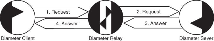
Figure 2.11 Diameter relay.
A relay agent can act as request aggregator for multiple clients and send those requests to other realms. This reduces the configuration burdens on both clients and servers. Diameter clients don't need to be configured with the security information required to communicate with Diameter servers in other realms, and Diameter servers don't need to be reconfigured when clients are added, removed, or changed.
2.9.4 Proxy Agents
Like relay agents, proxy agents forward requests and responses; however, proxy agents provide more services since they can enforce resource usage policies and can provide access control and provisioning. For example, a proxy may inform a server that a session is terminated with a Session‐Termination‐Request message. Because proxy agents make policy decisions, they must understand message semantics and only support those applications for which they have been designed. Thus, a Diameter proxy is referred to as a Diameter Application proxy, where Application is the application that it supports.
2.9.5 Translation Agents
A Diameter translation agent translates between another AAA protocol, such as RADIUS, and Diameter. Translation agents can only translate requests and answers of applications that they recognize. Since Diameter supports long‐lived sessions, translation agents maintain the session state. A translation agent can provide a gateway to Diameter infrastructure, which allows legacy systems to migrate at a slower pace.
References
- 1 IANA. Radius Types: Authentication, Authorization, and Accounting (AAA) Parameters, Jan. 2016. http://www.iana.org/assignments/aaa‐parameters/aaa‐parameters.xhtml.
- 2 D. Sun, P. McCann, H. Tschofenig, T. Tsou, A. Doria, and G. Zorn. Diameter Quality‐of‐Service Application. RFC 5866, Internet Engineering Task Force, May 2010.
- 3 J. Postel. Transmission Control Protocol. RFC 0793, Internet Engineering Task Force, Sept. 1981.
- 4 R. Stewart. Stream Control Transmission Protocol. RFC 4960, Internet Engineering Task Force, Sept. 2007.
- 5 T. Dierks and E. Rescorla. The Transport Layer Security (TLS) Protocol Version 1.2. RFC 5246, Internet Engineering Task Force, Aug. 2008.
- 6 M. Tuexen, R. Seggelmann, and E. Rescorla. Datagram Transport Layer Security (DTLS) for Stream Control Transmission Protocol (SCTP). RFC 6083, Internet Engineering Task Force, Jan. 2011.
- 7 S. Kent and K. Seo. Security Architecture for the Internet Protocol. RFC 4301, Internet Engineering Task Force, Dec. 2005.
- 8 D. Crocker and P. Overell. Augmented BNF for Syntax Specifications: ABNF. RFC 5234, Internet Engineering Task Force, Jan. 2008.
- 9 D. Mills, J. Martin, J. Burbank, and W. Kasch. Network Time Protocol Version 4: Protocol and Algorithms Specification. RFC 5905, Internet Engineering Task Force, June 2010.
- 10 T. Berners‐Lee, R. Fielding, and L. Masinter. Uniform Resource Identifier (URI): Generic Syntax. RFC 3986, Internet Engineering Task Force, Jan. 2005.
- 11 G. Zorn. Diameter Network Access Server Application. RFC 7155, Internet Engineering Task Force, Apr. 2014.