
3
Communication between Neighboring Peers
3.1 Introduction
This chapter describes in detail the principles of both transport and Diameter‐level connectivity between two adjacent Diameter nodes, known as peers. This chapter covers how the peers discover each other, how the peers connect and maintain connections, and how transport failures are handled. The chapter also covers advanced transport topics such as multi‐homed connections, head‐of‐line blocking, and multiple connection instances.
3.2 Peer Connections and Diameter Sessions
Two Diameter nodes that have a direct transport protocol connection between each other, known as a peer connection, are considered Diameter peers. The peer connection does not need to be directly connected from the IP point of view; there may be zero or more IP routers between the Diameter peers. Figure 3.1 shows a simple network topology where two peers are connected over an arbitrary IP network.

Figure 3.1 Diameter and transport connection between two peers.
The two peers may also establish a Diameter user session between each other. However, it is not required that a peer connection map directly to a Diameter session. Figure 3.2 shows a simplified network topology where Diameter nodes A and B have a Diameter user session that consists of multiple peer connections through an intermediating Diameter agent C.
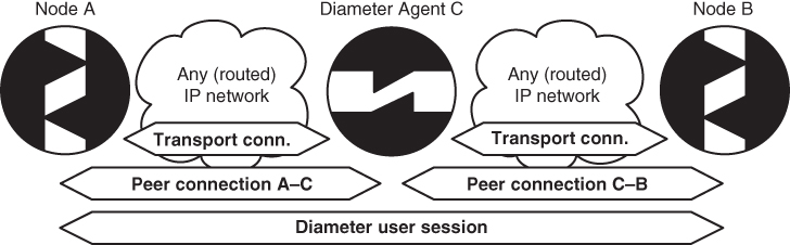
Figure 3.2 Diameter user sessions and peer connections.
It should be understood that Diameter decouples the peer connection and the Diameter user session. The lifetime and presence of Diameter user sessions are independent of the specific peer connections. On the other hand, a peer connection is directly dependent on the underlying transport connection.
3.3 The DiameterIdentity
Each Diameter node has a DiameterIdentity, which is a fully qualified domain name (FQDN). A node's DiameterIdentity must be unique within the host where the Diameter node is located. If the node is reachable via the Internet, its DiameterIdentity should be globally unique as well. It is important that the DiameterIdentity is unique because of its role in Diameter connection management. A node uses a peer's DiameterIdentity as the peer table lookup key (see Section 3.7) and tracks the peer state machine (see Section 3.8.2). A node may also use a DiameterIdentity to discover peers dynamically (see Section 3.4.2).
A DiameterIdentity maps to one or more IP addresses of a Diameter node. A Diameter node may be:
- single‐homed and single addressed,
- single‐homed and multiple addressed, or
- multi‐homed and multiple addressed.
An IP address belongs to one and only one DiameterIdentity, that is, to a single Diameter node. A networking node may host multiple Diameter nodes and thus multiple DiameterIdentities, for example when every Diameter node is a separate virtual machine or a process. Regardless, the requirement holds that an IP address always maps to a single DiameterIdentity and each Diameter node has a single unique DiameterIdentity. We will discuss the role of multiple IP addresses later in the context of multiple connection instances in Section 3.9.4.
3.4 Peer Discovery
Peer discovery refers to the mechanism that a Diameter node uses to discover other peers to which it should attempt to establish connections with. There are two types of peer discovery: static discovery, in which connection information for adjacent peers is configured into the Diameter node, and dynamic discovery, in which a Diameter node uses Domain Name System (DNS) to find its adjacent peers.
3.4.1 Static Discovery
Static peer discovery is the traditional way for AAA systems to find their adjacent peers. Diameter is no exception. A typical way for a Diameter node to learn its peers, their IP addresses or FQDNs, and the rest of configuration information (such as the security‐related parameters and associated realms) is to read a configuration file or a database. As a result, the peer configuration and especially the discovery are static in nature.
Once the peer configuration is known, Diameter node's peer and routing tables are configured appropriately. Apart from the application identifier information, the peer discovery is now completed and remains static until new peer configuration information is added, changed, or removed through administrative actions.
3.4.1.1 Static Discovery in freeDiameter
freeDiameter statically discovers its peers by reading its configuration file. By default, freeDiameter will reject connections from unknown peers. An example of peer configuration can be found in the freeDiameter‐1.conf file found in the /src/doc/single_host/ directory. At the end of the file is the following line:
ConnectPeer = "peer2.localdomain" { ConnectTo = "127.0.0.1";No_TLS; port = 30868; };
Where peer2.localdomain is the DiameterIdentity of the peer. Note that the configured DiameterIdentity must match the information received inside the CEA or the connection will be aborted. The No_TLS parameter tells freeDiameter to assume transparent security instead of TLS.
The ConnectPeer configuration has the following general format:
ConnectPeer = "<diameterid>" [ { <parameter>; <parameter>; ...} ] ; The following parameters can be specified in the peer's parameter list, separated by semicolons:
- IPv4 or IPv6 address of the peer:
ConnectTo = "<IP_address>" - Transport protocol information:
No_TCP,No_SCTP,No_IP(use only IPv6 addresses),No_IPv6(use only IPv4 addresses),Prefer_TCP,TLS_old_method(use the RFC 3588 method for TLS protection, where TLS is negotiated after CER/CEA exchange is completed),No_TLS. Note that DTLS is not yet supported. - Port information:
Port = <port_number> - Tc Timer setting, which specifies how often to attempt to make a transport connection when one doesn't exist:
TcTimer = <seconds>. The default value is 30 seconds. For more information about the Tc Timer, see Section 3.8.1. - Tw Timer setting, which is used to trigger timeouts at the Diameter application level:
TwTimer = <seconds>. The default value is 30 seconds. For more information about the Tw Timer, see Section 3.8.1 . - GNU TLS priority string, which allows you to configure the behavior of GNUTLS key exchanges:
TLS_Prio = "<priority>". The default value isNORMAL. See the gnutls_priority_init function documentation for more information. - Realm, if the peer does not advertise the given realm, reject the connection:
Realm = "<realm>"
If a parameter is not specified, its default is used. Here are some more examples of peer configuration:
ConnectPeer = "aaa.wide.ad.jp";ConnectPeer = "old.diameter.serv" { TcTimer = 60; TLS_old_method;No_SCTP; Port=3868; } ;
3.4.2 Dynamic Discovery
When no matching statically configured peers exist or if none of its existing peers responds, a Diameter node can discover adjacent peers dynamically by consulting the DNS. The DNS is a system that primarily translates (fully qualified) domain names into IP addresses.1
The benefits of the dynamic discovery are obvious. Dynamic discovery eases the management of the Diameter nodes since the peer and routing information does not need to be known before initial deployment. Adding new peers or destination realms ideally requires no additional configuration. The administrator of a realm populates the realm's master DNS servers with the information of the Diameter nodes that he or she wants to be discoverable. There may be multiple provisioned nodes per realm with the same or different set of supported Diameter applications, transport protocols, and security profiles. If security is used, then appropriate certificates for all peers with which the Diameter node may attempt to establish a connection must be installed and available.
It is important to understand that DNS‐based dynamic discovery is different from resolving a Diameter peer's DiameterIdentity to an IP address for transport connection establishment, although at the end of the discovery process DiameterIdentity to IP address resolving also takes place. When looking up peers in DNS, the Diameter node uses the destination realm, the preferred/supported transport, and security mechanisms, rather than using the peer's DiameterIdentity.
Although it may appear similar, dynamic discovery is not the same as dynamic AAA routing. The discovery helps in finding peers, but there may be a number of intermediate Diameter agents between the discovery initiator and the discovered peer that must be traversed. The details of different deployments are discussed in more detail in Chapter 4.
The concepts of DNS span many IETF specifications and have evolved over the years. The following paragraphs provide an overview of how Diameter uses DNS.
RFC 3588 specified the use of an older form of Naming Authority Pointer (NAPTR) [2] resource records (RRs), which were then used to retrieve Service Location (SRV) RRs [3], which provide locations of specific nodes based on the transports the nodes support. An example of legacy NAPTR records for Diameter can be found in Figure 3.3.
;; order pref flags service regexp replacementIN NAPTR 25 50 "s" "AAA+D2S" "" _diameter._sctp.example.comIN NAPTR 100 50 "s" "AAA+D2T" "" _aaa._tcp.example.com
Figure 3.3 An example of legacy NAPTR records.
These records tell the querying node that SCTP and TCP are supported. The lower order number given for the SCTP entry indicates that SCTP is preferred. The flags column tells the querying node what the replacement column contains. If "A" is present in the flags field, then the replacement value contains a domain name to be used to look up an address record (known as an A or AAAA record 4,5). If the flags field is empty, then the querying node should use the replacement value in a new NAPTR query. Note that this recursion is error prone and has since been deprecated in newer DNS specifications.
The "s" flag tells the querying node to use the replacement value, in this case _diameter._sctp.example.com, in an SRV query to determine the location of the service. Figure 3.4 shows the results of the SRV query.
;; Priority Weight Port TargetIN SRV 0 1 5060 server1.example.comIN SRV 0 2 5060 server2.example.com
Figure 3.4 Results of an SRV query.
The querying node then uses the domain name found in the SRV RR target field to do an address record lookup. Once an IPv4 or IPv6 address is retrieved, the node has the information necessary to attempt a transport connection with the discovered peer. However, note that these DNS records do not provide information on supported Diameter applications. If DNS returned multiple Diameter nodes, the querying node has to iterate through these Diameter nodes to find a node that supports the same applications. This means establishing a peer connection, running the CER/CEA exchange, and then possibly discarding the connection if no desired applications are found. In a large Diameter network, this could add a considerable amount of unnecessary connection attempt overhead and delay during the discovery phase.
These concerns resulted in the development of RFC 6408 6, which introduced a dynamic discovery procedure based on the Dynamic Delegation Discovery Service (DDDS) 7 and Straightforward‐NAPTR (S‐NAPTR) 8, which added Diameter Application‐Id information to the S‐NAPTR records.
Figure 3.5 shows an example of S‐NAPTR records that show support for particular Diameter applications. In these S‐NAPTR records, Diameter applications are indicated in the service field by using a naming convention aaa+ap<Application‐Id>. In the example, the server supports both the NASREQ application (Application‐Id 1) and the Credit Control application (Application‐Id 4).
;; order pref flags service regexp replacementIN NAPTR 50 50 "s" "aaa:diameter.sctp" "" _diameter._sctp.ex1.example.comIN NAPTR 50 50 "s" "aaa+ap1:diameter.sctp" "" _diameter._sctp.ex1.example.comIN NAPTR 50 50 "s" "aaa+ap4:diameter.sctp" "" _diameter._sctp.ex1.example.com
Figure 3.5 S‐NAPTR records showing support for Diameter applications.
RFC 6733 aligned with the NAPTR DDDS application‐based, dynamic‐discovery mechanism defined by RFC 6408. Also, although RFC 6733 states that using DNS for dynamic discovery is mandatory to implement, it is optional to deploy. RFC 6733 also does not mandate the use of the application identifier part of the RFC 6408 algorithm, so Figure 3.6 is also a valid example of an RFC 6733 style S‐NAPTR record.
;; order pref flags service regexp replacementIN NAPTR 50 50 "A" "aaa:diameter.dtls.sctp" "" "node.example.com"
Figure 3.6 An RFC 6733 style S‐NAPTR record.
Figure 3.7 shows an example of DNS RRs for the realm “example.com”. The DNS configuration shows support for TLS (or no TLS) transport over TCP, the use of SRV indirection, and the Mobile IPv6 Auth Diameter application (Application‐Id 8 9). Note that _diameters in the replacement field indicates a secure version of the transport protocol.
;; provisioned under the "$ORIGIN example.com.";;;; order pref flags service regexp replacementIN NAPTR 50 50 "S" "aaa+ap8:diameter.tls.tcp" "" "_diameters._tcp.mip.example.com"IN NAPTR 50 50 "S" "aaa+ap8:diameter.tcp" "" "_diameter._tcp.mip.example.com";; Priority Weight Port Target_diameters._tcp.mip IN SRV 0 1 5868 ha.mip.example.com_diameter._tcp.mip IN SRV 0 1 3868 ha.mip.example.com;;ha.mip IN A 192.0.2.1ha.mip IN AAAA 2001:bd8:dead:beef::c000::201
Figure 3.7 An example of DNS RRs for realm “example.com”.
Legacy applications still use RFC 3588 style NAPTRs and therefore the DNS administrator for a Diameter deployment should also provision NAPTR RRs in RFC 3588 style for backward compatibility.
The following algorithm example for dynamic discovery follows the original description in RFC 6733 and the modifications introduced by RFC 6408:
- 1. Before starting the procedure, the querying node must know the realm to contact. The querying node may extract the realm information, for example from the realm part of the
User‐NameAVP value found in the request message. Details of using information from theUser‐NameAVP can be found in Section 4.3.1. - 2. The Diameter node performs a NAPTR query for a service in the particular realm (e.g., “example.com”).
- 3. If the returned NAPTR RRs contain service fields formatted as
aaa+ap<X>:<Y>, where<X>is a Diameter Application‐Id and<Y>is one of the following, indicating the supported transport protocol:- •
diameter.tcp - •
diameter.sctp - •
diameter.dtls - •
diameter.tls.tcp
then the queried realm supports the DDDS NAPTR application as defined in RFC 6408. An example service field is the following:
aaa+ap1:diameter.tcp.- (a) If the
<X>contains the desired Application‐Id and the<Y>contains a desired transport protocol and security combination, the resolver resolves the replacement field to a target host using the lookup mechanism defined by the flags field. - (b) If neither
<X>nor<Y>contain desired values, then the querying node discards the current entry and examines the next returned NAPTR RR, if such exists.
- •
- 4. If the returned NAPTR RRs contain service fields formatted as
aaa+ap<X>, the querying node resolves the replacement field to a target host using the lookup mechanism defined by the flags field 8. All possible transport protocols are tried in the following order: TLS, followed by DTLS, then by TCP, and finally by SCTP. - 5. If the returned NAPTR RRs contain service fields formatted as
aaa:<Y>, where<Y>indicates the supported transport protocol, then the queried realm supports the simplified DDDS NAPTR application given in RFC 6733.- (a) If the
<Y>contains a supported and preferred transport protocol and security combination, the querying node resolves the replacement field to a target host using the lookup mechanism defined by the flags field.
- (a) If the
- 6. If the returned NAPTR RRs contain service fields formatted as either
aaa+D2Tfor TCP oraaa+D2Sfor SCTP,2 the realm supports dynamic discovery defined in RFC 3588, and the querying node should fall back to using legacy NAPTR 2. - 7. If none of the above returned a positive result, the queried realm does not support NAPTR‐based Diameter peer discovery. The querying node requests SRV RRs directly from the realm using the same transport protocol prioritization as described above.
- 8. If the SRV query fails, then the querying node may try to resolve address records (A/AAAA RRs) for the target hostname specified in the SRV RRs and following the rules laid out in 3, 6,10.
- 9. If all of the above fails, the querying node returns an error to the Diameter application implementation.
3.4.2.1 Dynamic Discovery and DiameterURI
Diameter nodes can also be discovered by inspecting AVPs, for instance the Redirect‐Host AVP, that use the derived datatype DiameterURI. A node may receive one or more Redirect‐Host AVPs in an answer message from a redirect agent to inform the requesting node to send the request to a different Diameter node.
The DiameterURI datatype follows the Uniform Resource Identifier (URI) syntax 11 and can capture peer node's port number, FQDN, transport protocol, and security. Below is an example syntax of the DiameterURI with and without secure transport. Note that we are showing just the high‐level URI syntax and not the actual Augmented Backus–Naur Form (ABNF) 12 details for the URI. For the ABNF details, see RFC 6733.
A Diameter peer that does not support secure transport is represented by a DiameterURI starting with aaa:
"aaa://" FQDN [port] [transport] [protocol]
A Diameter peer that supports secure transport is represented by a DiameterURI starting with aaas:
"aaas://" FQDN [port] [transport] [protocol]
The example DiameterURI below is one of the DNS examples with TCP transport and TLS security from Section 3.4.2 :
aaas://ha.mip.example.com:5868;transport=tcp;protocol=diameter
There are a few notes to make about the DiameterURI. First, the port parameter is used to specify non‐standard port numbers for Diameter. If the parameter is absent, default ports apply (TCP and SCTP 3868, TLS/TCP and DTLS/SCTP 5868).
Second, the transport parameter allows UDP to be specified as the transport protocol, even though it is not possible to use UDP with Diameter. However, closer inspection of the DiameterURI reveals that it also allows AAA protocols other than Diameter to be specified in the protocol parameter, namely both RADIUS 13 and TACACS+ 14. Obviously, in Diameter deployments only those transports and protocols supported by Diameter can be used.
Finally, coming back to the dynamic discovery, the FQDN given in the URI needs to be resolved using DNS. In this case, a normal A/AAAA query is used 4, 5. Furthermore, differing from the general URI specification, the DiameterURI always contains an FQDN, and never an IP literal.
3.4.2.2 DNS Further Reading
As mentioned earlier, DNS is a broad topic covered in many IETF RFCs. For more information, consult the RFCs mentioned in this section: RFC 6408 6, which covers S‐NAPTR usage for Diameter, RFC 3958 8, which covers S‐NAPTRs and Dynamic Delegation Discovery Service, and RFC 2783 3, which covers SRV records. RFC 1035 4 covers A records and RFC 3596 5 covers AAAA records. An overview of DNS terminology is given in RFC 7719 15.
3.5 Connection Establishment
As we know, the transport connection is either over Transmission Control Protocol (TCP) 16 or over Stream Control Transmission Protocol (SCTP) 17, with or without Transport Layer Security 18,19. The transport connection between two peers is transparent to the “Diameter layer” and applications as soon as it gets established. There has been a notable change in the transport connection handling from the original Diameter base protocol, RFC 3588, to RFC 6733. In RFC 3588 the secure versions of the TLS/TCP or TLS/SCTP 20 transport protocols used the same port number, 3868, as their plaintext counterparts. RFC 6733 specifies that TLS/TCP and DTLS/SCTP connections must use port number 5868.3 However, the default port numbers can be overridden by dynamic peer discovery (see Section 3.4.2 ).
The change of transport security handling has impacts on the transport connection implementation in general (see Chapter 5 for a detailed discussion on the security impacts), since security is not negotiated after the transport connection has been set up. This simplification follows the current trend of doing transport‐layer security. The other notable enhancement is that the Diameter capabilities exchange messages Capability Exchange Request (CER) and Capability Exchange Answer (CEA) are no longer sent in clear text. For backward compatibility, a Diameter node may still implement the RFC 3588 way of setting up the transport‐level security after the capabilities exchange.
3.5.1 The Election Process: Handling Simultaneous Connection Attempts
Since Diameter is a peer‐to‐peer protocol where either end of the communication can be a server or a client or both, either end can initiate peer connections. The client or server roles of a Diameter node are defined at the application level (or also at the implementation level, as a Diameter node may be developed in a way that it serves only a specific role, such as a server). It is possible that both Diameter peers initiate a peer connection establishment procedure (almost) simultaneously. For those cases, the Diameter base protocol describes an election procedure to decide which one of the two connections remains as the active peer connection. The election takes place at the transport connection receiver side during the capability exchange. The receiver of a CER message compares the DiameterIdentity contained in the Origin‐Host AVP included in the CER message to its own DiameterIdentity. The comparison is done at the octet level comparing the two identities as blobs of octets. The peer whose DiameterIdentity is “greater” is the winner of the election. The election winner closes the transport connection that it initiated. After the election, there is only one transport connection left, which will become the peer connection between the two Diameter nodes.
3.6 Capabilities Exchange
The capabilities exchange occurs after the transport connection with the peer has been established. The initiator of the transport connection sends a CER message immediately to its peer after the connection establishment. The capabilities exchange has an important role in the Diameter base protocol. It is used by the adjacent peers to discover each other's identity, capabilities, configuration information, possibly supported security mechanisms/cipher‐suites (for the so‐called in‐band security for backwards compatibility), and the common set of supported application identifiers. If peers do not have a single application (or possibly a security mechanism) in common, then the responder includes an error in its CEA message (such as DIAMETER_NO_COMMON_APPLICATION or DIAMETER_NO_COMMON_SECURITY). After sending an error‐indicating CEA, the Diameter node should also close the transport connection.
Once the peers have reached the “open” state (see Section 3.8.2 ), the capabilities exchange usually does not happen again. Any CER message received in the open state is discarded. If a peer receives a new transport connection attempt and the subsequent CER with the same DiameterIdentity (as learned from the Origin‐Host AVP) for which the peer already has a peer table entry, the peer typically rejects the CER and closes the incoming transport connection. However, there are exceptions to this. The first is multiple connection instances, which is discussed in detail in Section 3.9.4 . Another exception is the RFC 6737 21 extension to the base protocol that allows new applications to define whether the capabilities exchange can be rerun in order to update peer information without tearing down and then re‐establishing the transport connection.
If the CER is received from an unknown peer, i.e., the DiameterIdentity is not recognized, the receiving peer may either silently discard the CER, which will eventually cause the connection attempt to time out, or respond with a CEA containing the DIAMETER_UNKNOWN_PEER error code. In both cases the receiving peer closes the transport connection. However, such stringent policy does not work well in larger Diameter deployments since every Diameter agent and server would need to know in advance all possible peers that can contact them, unnecessarily complicating the administration of such a deployment. If the Diameter deployment has a proper public key infrastructure in place, there is not a need to know peer identities in advance. The legitimacy of the other peer can be verified using cryptographic means.
3.6.1 freeDiameter example
Before going through the details of the messages used for the management of peer connections, here is a short hands‐on example using freeDiameter to establish such a connection. This example assumes that you have already followed the instructions in Appendix A.
Run the following commands on the client machine to configure and start freeDiameter:

Run the following commands on the server machine to configure and start freeDiameter:

Note that this configuration is very similar to the one in Appendix A, the only difference being that the messages sent and received are displayed in a more readable form. We will use the output of those commands in the following paragraphs, which discuss the role of those commands in detail.
If we look at our freeDiameter log from the client.example.net vitual machine (VM), we can see the following message exchange (some lines stripped for readability):

3.6.2 The Capabilities Exchange Request
Figure 3.8 shows the CER message Command Code Format (CCF). The peer receiving the CER message learns the transport connection initiator's DiameterIdentity from the Origin‐Host AVP and the realm from the Origin‐Realm AVP. Note that the DiameterIdentity already contains the realm part, so the Origin‐Realm AVP is duplicate information. The receiving peer uses the DiameterIdentity to look up the peer table for a possible existing entry.
<CER> ::= < Diameter Header: 257, REQ >{ Origin-Host }{ Origin-Realm }1* { Host-IP-Address }{ Vendor-Id }{ Product-Name }[ Origin-State-Id ]* [ Supported-Vendor-Id ]* [ Auth-Application-Id ]* [ Inband-Security-Id ]* [ Acct-Application-Id ]* [ Vendor-Specific-Application-Id ][ Firmware-Revision ]* [ AVP ]
Figure 3.8 CER message format.
The receiving peer looks for a mutually supported application by examining both the Auth‐Application‐Id and Vendor‐Specific‐Application‐Id AVPs in the CER message. Note that the relay Application‐Id is advertised only if the peer is a relay agent. Advertising other Application‐Ids along with the relay Application‐Id makes little sense. The Diameter base protocol does not explicitly prohibit such behavior, though.
Another notable detail in the CER message is the mandatory presence of the Host‐IP‐Address AVP(s). The use case for multiple IP addresses is clear in a case of SCTP transport protocol, since the initial SCTP association does not necessarily contain all possible IP addresses the SCTP association can use during its lifetime 22 in a multi‐homed/‐addressed host. Including multiple IP addresses in the CER message in a case of TCP transport does not have a known “standard” use case. The situation might change with the introduction of the Multipath TCP (MPTCP) 23. However, the use of MPTCP has not been specified for Diameter base protocol. For now, including multiple IP addresses when using the TCP transport or using MPTCP is not recommended.
Finally, since RFC 6733 deprecated the use of the Inband‐Security‐Id AVP for negotiating TLS, its use should be avoided unless the network administrator knows the Diameter deployment uses a mixture of RFC 6733 and RFC 3588 nodes.
3.6.3 Capabilities Exchange Answer
Figure 3.9 shows the CEA message CCF. The receiving peer responds to the CER with a CEA if it allows the transport connection to be established (the receiving peer can always reject the incoming transport connection establishment attempt). The CEA will also contain the list of application identifiers that the peer supports. Subject to the local policy both Auth‐Application‐Id and Vendor‐Specific‐Application‐Id AVPs may contain either all Application‐Ids supported locally, or only those that are mutually supported by both peers (with the exception of the relay Application‐Id).
<CEA> ::= < Diameter Header: 257 >{ Origin-Host }{ Origin-Realm }1* { Host-IP-Address }{ Vendor-Id }{ Product-Name }[ Origin-State-Id ][ Error-Message ][ Failed-AVP ]* [ Supported-Vendor-Id ]* [ Auth-Application-Id ]* [ Inband-Security-Id ]* [ Acct-Application-Id ]* [ Vendor-Specific-Application-Id ][ Firmware-Revision ]* [ AVP ]
Figure 3.9 CEA message format.
The rest of the CER and CEA AVPs are more or less for further information about the peer, and can be used for diagnostic purposes or to build a product‐specific or a vendor‐specific handling of the peer. It is worth mentioning that Origin‐State‐Id AVP can be used to determine whether the peer has recently restarted. The AVP itself is a monotonically increasing value (a counter or something derived from time) that is updated every time the Diameter node is started. If the Origin‐State‐Id AVP differs from a previously seen value, then the peer knows something has happened to the other peer and that “non‐Diameter state knowledge”, for example of previously authenticated users, may have been lost.
3.6.4 Hop‐by‐Hop Identifiers
Hop‐by‐Hop Identifiers are used between adjacent Diameter nodes to map answer messages to request messages. The lifetime of a Hop‐by‐Hop Identifier is the duration of the transaction state. The state is removed after the node has seen an answer for a request that it has sent or forwarded earlier.
The identifiers are locally unique to a Diameter node and are always selected or generated by the Diameter node that originated or forwarded the request message. This also implies that the uniqueness of the Hop‐by‐Hop Identifier is tied to the peer host identity and more precisely to the peer connection identified by the host identity (the identity that also goes into the Origin‐Name AVP in the CER message).
However, the Diameter node that generated the Hop‐by‐Hop Identifier must be prepared to receive an answer message through a different transport connection from which the request was sent.4 There are two cases here: multiple transport connection instances between peers (see Section 3.9.4 ) or a collection of Diameter nodes (agents) that are able to share the hop‐by‐hop and transaction state information (and re‐route answer messages between each other) in an implementation‐dependent manner. The latter way of functioning has been known to cause interoperability issues.
Typically, if the transport connection fails in an answer message direction, it is better to discard the answer message and let the downstream nodes handle the failover procedures entirely. RFC 6733 only addresses failover and failback procedures to the upstream direction, i.e., from the request message failover point of view.
3.7 The Peer Table
A peer table is a data structure internal to a Diameter node that holds the information of adjacent Diameter peers with which the Diameter node has transport‐level connections established. A peer table entry contains the following information:
- Host Identity
Identifies the remote peer. This identity is the DiameterIdentity found in the
Origin‐HostAVP from the CER or CEA during the capability exchange. It is assumed that the host identity does not change during the lifetime of the transport connection. - Status
Provides the current state of the connection with the peer. Details on the specific states are covered in Section 3.8.2 .
- Static or Dynamic
Notes whether the peer table entry was dynamically discovered or manually configured.
- Expiration Time
Specifies the time when the peer table entry has to be discarded or refreshed. In the case of a dynamically discovered peer table entry, the time‐to‐live from the DNS Resource Record (RR) specifies the time. If secure transport and public key certificates are in use, then the expiration time must not be greater than that of the certificates.
- TLS/TCP and DTLS/SCTP Enabled
Indicates whether secure versions of the transport protocols are to be used when sending Diameter messages.
- Security Information (optional)
Contains keys, certificates, and such as needed by the secure transport connection.
- Implementation‐specific Data (optional)
Contains any arbitrary information that is not covered by any Diameter specification. A good example is peer ranking information that the Diameter node uses for an educated peer selection. Another example could be storing all the IP addresses to which the remote peer DiameterIdentity resolves to.
The number of peer tables is determined by the number of peers the node is connected to or is attempting to connect to. There is a separate peer state machine for each peer table entry that tracks the state of the connection. The peer state machine is covered in detail in Section 3.8.2 . Typically there is a single peer table entry and a transport‐level connection for each remote peer. However, there are exceptions to this rule that will be discussed in more detail in Section 3.9.4 .
The peer table is referenced from the routing table, and the intended next‐hop peer node's host identity is used as the lookup key. The next‐hop peer node identity is named as the server identifier in the routing table. The routing table is covered in more detail in Chapter 4.
The Diameter base protocol is silent on how the peer table lookup is done when multiple entries exist for the same host identity, which is the case when multiple transport connection instances are supported for the same remote peer (see Section 3.9.4 for details). At a minimum the Diameter node should able to distinguish between the transport connections based on the transport protocol level information. The local source port must be different (unless different source IP addresses are used) if the destination port and the IP address(es) are the same.
How a routing table and a peer table keep each other in sync is left to the implementation. There are situations where one will need to modify other's tables, for instance the expiration of the table entry in either the routing table or the peer table. Another example is the permanent failure of the transport connection. Although transport connections and peer connections are dependent on each other, a disconnection at the transport layer does not always imply immediate purging of the corresponding peer table entry. A Diameter node can be quite persistent trying to re‐establish transport connections with peers in the event of a networking failure (refer to Section 3.8.1 and the Tc timer), specifically those that have a statically configured peer table entry.
3.8 Peer Connection Maintenance
The Diameter base protocol has a set of commands that are designed to maintain the connection between peers. These commands use the Application‐Id 0, which is the identifier for the Diameter base protocol:
- CER and CEA (discussed in Section 3.6) are considered to be part of the generic peer connection management in the Diameter base protocol.
- Device Watchdog Request (DWR) and Device Watchdog Answer (DWA) are used to check the health and liveness of the peer connection. A Diameter node actively monitors the condition of the transport connection between peers at two levels: at the transport protocol level using the mechanisms provided by the transport protocol itself, and at the Diameter base protocol layer using watchdog messages (DWR and DWA). The Diameter layer DWR/DWA messages allow the detection of peer failures, either because the peer is unreachable or because the peer Diameter “process” has failed.
- Disconnect Peer Request (DPR) and Disconnect Peer Answer (DPA) are used to inform the other end that the peer connection is going to be closed. The DPR also contains the mandatory
Disconnect‐CauseAVP that the disconnection‐initiating peer uses to inform the other peer why the transport connection is to be closed (such asREBOOTINGetc). See Section 3.8.2 for more information on the DPR and DPA message exchange.
Back to our running freeDiameter example from 3.6.1, you can see the following DWR/DWA exchange periodically:

To trigger a DPR/DPA exchange and to disconnect, press Ctrl‐C in the server:

The messages used for connection management (CER/CEA, DPR/DPA, and DWR/DWA) are like any other Diameter messages, except that they have certain restrictions:
- These messages cannot be forwarded. They are only meant to be used between two adjacent peers. In this case the “P” flag is also unset in the Diameter message header.
- The DWR, DPR, and CER messages must not be (re)sent to an alternate peer (if a connection for such exists) upon transport failures.
- The DWR/DWA have special periodic scheduling rules and intervals. See Section 3.8.1 for details.
3.8.1 Transport Failure, Failover, and Failback Procedures
The Diameter base protocol does not describe how to recover from a transport connection failure. Rather, it references the algorithm and procedures described in RFC 3539 24.
It is recommended that a Diameter node maintains multiple transport connections to servers or agents. The Diameter base protocol recommends maintaining at least two transport connections to alternate peers per realm for failover purposes. This recommendation is often also interpreted as a recommendation to have at least two transport connections between each peer, which was not the original intent. One of the transport connections is selected as the primary connection, which is used primarily for sending requests. The other connection is, naturally, used as a secondary for failover purposes. However, a Diameter node may also load balance requests among multiple peers, in which case the role of primary and secondary transport connections is no longer obvious. It is also worth noting that a Diameter node may maintain multiple secondary connections that are either inactive or closed, and promoted on an as‐needed basis to the active secondary connection.
As mentioned in Section 3.8, a Diameter node monitors its peer connection status at two levels: at the transport level and at the Diameter application level. Using Diameter base protocol messaging to detect connection failures may look redundant, since the transport protocols will notify the Diameter application if a connection terminates abnormally. However, the watchdog mechanisms at the Diameter application layer enable the detection of issues with networking paths and also application failures at the Diameter peer, which would otherwise be detected only after expiration of transport‐dependent timers. Once a transport failure has been detected, the Diameter node switches to the secondary (backup) transport connections, if they exist.
Figure 3.10 illustrates the Diameter transport connection failover and failback algorithm from RFC 3539 using a finite state machine. A finite state machine is a model of computer program behavior that can be in exactly one of a finite number of states at any given time. A specific event or trigger causes the state to transition to a new state. The states in the figure are shown from the peer control block (PCB) point of view. The PCB, which can be considered to be the peer state machine or at least an integral part of it, keeps state for a transport connection. The “initial” state in the illustrated state machine is the “A” state, and the exit state in a case of transport disconnection is the “B” state. Both “A” and “B” are further explained in Figure 3.11. The failover and failback state machine is entered from the state “A” when there is at least one active peer connection promoted as a (temporary) primary connection.

Figure 3.10 Diameter peer connection failover and failback state machine.

Figure 3.11 Diameter transport connection state machine.
The transport connection can be to either a primary or a secondary peer, i.e., using primary or secondary transport connections. A Diameter node maintains a watchdog timer called Tw. The Tw timer is used to trigger timeouts at the Diameter application level. When the Tw timer expires, it triggers an attempt to re‐establish a peer connection that has no existing transport connection (refer to the state machine transitions from “DOWN” to “DOWN Attempting Open” in Figure 3.11). The Tc timer, which specifies how often to attempt to make a transport connection, is actually same as the Tw timer but is used only to trigger an attempt to establish a peer connection when one does not exist. This is shown in the state machine transition from “NO PEER CONNECTION” to “INITIAL” in Figure 3.11.
The Tw timer has an initial value TwInit that defaults to 30 seconds (just like the Tc timer) and must not be lower than 6 seconds. A low initial value increases the chances of duplicate messages, as well as the number of spurious failover and failback attempts. In order to avoid all PCBs in a Diameter node expiring at the same time, the formula for Tw adds intentional jitter to it. In the state machines, we refer to the formula as “SetTw”:
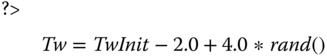
The Tw timer is reset any time any message from the peer is received. If the Tw timer expires, the Diameter node sends a watchdog request to the peer, if it has not already sent one, and resets the Tw timer. A Diameter node does not retransmit watchdog requests.
In order for a Diameter node to failover, it must maintain a pending message queue for a given peer. When an answer message is received, the node removes the corresponding request, which can be determined by its Hop‐by‐Hop Identifier, from the queue. If the Tw timer expires and a watchdog response is pending, then failover is initiated. The node sends all messages in the pending message queue to an alternate peer, if one is available. Once the peer's Tw timer has expired at least twice, the node can close or reset the primary connection. The node sends subsequent requests to the alternate peer until the Tw timer on the primary connection is reset.
In the state machine, state transitions identify the event that triggered the transition (prefixed with “‐”) and the action that occurs during the state transition (prefixed with “+”). Table 3.1 lists the events used in the state machines.
Table 3.1 State machine transition events.
| Event | Description |
| Any msg | An arrival of any Diameter message. |
| Tc Expiry | An expiration of the Tc timer. |
| Tw Expiry | An expiration of the Tw timer. |
| Conn Down | The transport connection (TCP or SCTP) goes down. |
| DWA | An arrival of a DWA message. |
| non‐DWA | An arrival of a Diameter message other than DWA. |
Table 3.2 lists the actions that are taken during state transitions. It is easier to follow the state machines when you keep in mind that each PCB is equal to a transport connection and a peer connection. So, if there are two peer connections, then there are also at least two PCBs; one being the primary and the others secondaries. Essentially, there may be multiple concurrent PCBs in the system. In the case of multiple secondary PCBs, some of them may be inactive or even closed (i.e., the actual transport protocol connection has not been established). When a Failover action takes place, some of the active secondary PCBs are temporarily promoted to the primary connection. When a Failback action takes place, the previous primary PCB is again promoted as the primary connection. Which peer connection is primary and which are secondaries is typically determined by configuration, and nothing prevents an implementation from promoting a secondary peer connection to primary status permanently at runtime.
Table 3.2 State machine transition actions.
| Action | Description |
| SetTw | Reset the Tw and the timer to the initial value (see Formula 3.1). |
| Send DWR | Send a DWR. |
| Failover | Promote the secondary transport connection to the active temporary primary connection (and possibly switch a peer). |
| Failback | Switch back to the original primary transport connection as the active primary connection (and possibly switch a peer). |
| Close Conn | Close the transport connection. |
| Conn Up | Establish the transport connection. |
| Attempt Open | Initiate opening of the transport connection. |
When a failover or a failback takes place, queued requests that have not yet received a matching answer are re‐sent over the transport connection that was promoted to active status. A Diameter node marks re‐sent request messages with the T command flag in the message header, which gives the receiver a hint that the request message was “potentially a retransmitted message”. Diameter agents that forward a request message must not change the T command flag setting.
Figure 3.11 illustrates the missing part of the Diameter transport connection state machine shown in Figure 3.10. Again, the state machine and its transitions need to be viewed from the peer control block perspective. The state machine is initially entered from the state “A” when the peer connection is first established. In the figure, the pseudo state “B” is entered only when the transport protocol connection disconnects. The pseudo state “B” is used as a “jump” within the state machine. The state machine also includes an additional state not found in RFC 3539: “NO PEER CONNECTION”. This state is used only when the transport connection is established for the very first time, for example after starting up the Diameter node. The handling of failure is different for initial transport connection establishment than for a previously operational connection.
To avoid switching between the primary and secondary transport connections, the RFC 3539 algorithm tries to be rather “lazy”, bringing a disconnected transport connection back to service. What is not shown in the state machine is the handling of the active and inactive/closed secondary peer connections. An implementation may silently close inactive peer connections in the background or establish new secondary connections based on internal logic. However, in order to avoid unnecessary establishing and closing transport protocol connections, RFC 3539 recommends keeping inactive connection around at least for 5 minutes.
The state machine in Figure 3.11 also shows where the CER/CEA exchanges discussed in Section 3.6 happen. Another enhancement over the state machines found in RFC 3539 are the inclusion of the Tc timer expiration and the Conn Down events.
3.8.2 Peer State Machine
The peer state machine is a finite state machine that an Diameter implementation uses to keep track of each peer's connection status. This peer state machine, which can be considered as the “main state machine” of the Diameter base protocol, is illustrated in Figure 3.12. It is worth noting that the peer state machine overlaps the state machines for peer connection and failover/failback to some extent (see Section 3.8.1 ), but the peer state machine tracks transport connections without the details of the algorithm discussed in Section 3.8.1 . For example, the peer state machine connection setup follows only the initial connection establishment procedure and lacks all failover/failback details.

Figure 3.12 Diameter peer state machine. The pseudo states ‘C’ and ‘R‐O’ are ‘jumps’ to the states ‘CLOSED’ and ‘R‐OPEN’ respectively.
The peer state machine is entered from the “INITIAL” state, which corresponds to the state and transition for the initial connection setup, that is, the transition from “INITIAL” to “A” in the transport connection state machine (see Figure 3.11).
Events in the peer state machine are prefixed with “‐” and are described in Table 3.3. Actions are are prefixed with “+” and are described in Table 3.4. For both the events and actions, the prefix “I‐” indicates the initiator side of the connection and similarly the prefix “R‐” indicates the receiver side of the connection. The notation “I/R” means that the event or action applies to both the initiator and the receiver. Note that the event timeout is different from the Tw timer‐caused timeout, and is rather an implementation‐defined value, for example to timeout a transport connection creation. Both timers may be the same, though, depending on the implementation.
Table 3.3 Peer state machine transition events.
| Event | Description |
| I/R‐Conn‐CER | A transport connection was established and a CER message received over the transport connection. |
| I/R‐Peer‐Disc | A peer connection was disconnected and an appropriate indication was received (see Section 3.8.1 ). |
| I/R‐Rcv‐DWR | A DWR message is received (see Section 3.8.1 ). |
| I/R‐Rcv‐DWA | A DWA message is received (see Section 3.8.1 ). |
| I/R‐Rcv‐DPR | A DPR message is received. The other peer indicates the transport connection is going to be closed. |
| I/R‐Rcv‐DPA | A DPA message is received. The other peer acknowledges it received the DPR and is ready for the transport connection to be closed. |
| I/R‐Rcv‐Disc | An indication was received that the transport connection was closed/disconnected. |
| I‐Rcv‐Conn‐Ack | An acknowledgement was received that the transport connection was established. |
| I‐Rcv‐Conn‐Nack | The transport connection establishment failed. |
| Timeout | A Diameter application‐defined timer expired while waiting for some event to happen. |
| Start | A Diameter application has signaled internally that a peer connection needs to be established with the remote peer. |
| Stop | A Diameter application has signaled that a peer connection needs to be closed. |
| Win‐Election | An election took place and the local node was the winner (see Section 3.8.2 ). |
| Snd‐Msg | A node sent any application message. |
| I/R‐Rcv‐Msg | A node received any application message (i.e., not CER/CEA, DWR/DWA or DPR/DPA). |
| I‐Rcv‐Non‐CEA | A message other than CEA is received. |
| I/R‐Rcv‐Non‐DPA | A message other than DPA is received. |
Table 3.4 Peer state machine transition actions.
| Actions | Description |
| I/R‐Snd‐DPR | Send DPR message. The peer indicates that it wants to close the transport connection. |
| I/R‐Snd‐DPA | Send DPA message and acknowledge the forthcoming closure of the transport connection. |
| I/R‐Snd‐DWR | Send DWR message, see Section 3.8.1 . |
| I/R‐Snd‐DWA | Send DWA message, see Section 3.8.1 . |
| I/R‐Snd‐CER | Send CER message over the newly established transport connection, see Section 3.6 . |
| I/R‐Snd‐CEA | Send CEA message over the newly accepted transport connection, see Section 3.6 . |
| I/R‐Peer‐Disc | The transport connection is disconnected and local resources are freed (this does not imply the Peer Control Block is freed, see Section 3.8.1 ). |
| Process‐DWR | Process and act according to the received DWR, see Section 3.8.1 . |
| Process‐DWA | Process and act according to the received DWA, see Section 3.8.1 . |
| Process‐CER | Process and act according to the received CER, see Section 3.6 . |
| Process‐CEA | Process and act according to the received CEA, see Section 3.6 . |
| Process | Process an application‐level Diameter message (i.e., not CER/CEA, DWR/DWA or DPR/DPA). |
| Error | The transport connection is disconnected either abruptly or in a clean way. Local resource related to the transport connection are freed (this does not imply that the Peer Control Block is freed, see Section 3.8.1 ). |
| Elect | The election takes place, see Section 3.8.2 . |
| R‐Accept | Accept an incoming transport connection (i.e., the connection that the CER arrives from). |
| R‐Reject | Reject an incoming transport connection (i.e., the connection that the CER arrived from). |
| Cleanup | Local resources related to the transport connection are freed and, if needed, the transport connection is also closed. This does not imply that the Peer Control Block is freed, see Section 3.8.1 ). |
| Drop | Silently discard the received Diameter message. |
3.9 Advanced Transport and Peer Topics
This section covers advanced topics on transport connection handling that may be hard to interpret unambiguously from the Diameter base protocol.
3.9.1 TCP Multi‐homing
The Diameter base protocol supports multi‐homing of Diameter nodes. In the Diameter context and specifically in the DiameterIdentity context that means a single DiameterIdentity may resolve in DNS to multiple IP addresses. These IP addresses may be configured into a single or multiple interfaces in a host that runs the Diameter node. If multiple IP addresses are configured and provisioned for a single DiameterIdentity, then the Diameter node must be able to originate and accept peer transport connections on all of those addresses. Note that multi‐homing in this context is different from multiple transport connection, which is discussed in Section 3.9.4 .
Interestingly, during the capability exchange (see Section 3.6 ) each peer informs the other about its IP addresses. Pedantically speaking, the Diameter peer has to include at least one IP address in the Host‐IP‐Address AVP. The Diameter base protocol does not define how these Host‐IP‐Address AVPs should be used for peer connection establishment. For example, the peer table (see Section 3.7 ) does not mandate storing IP address information, just the remote peer DiameterIdentity. Specifically, in a case of TCP there seems to be no use for informing the other peer of anything but the IP address. Perhaps some failover solutions could use additional IP addresses for faster failover, i.e., basically skipping the DNS query. This could make sense if all peers are statically configured. In this case peers could inform the other end that there are more addresses that can be used to reach the node. However, this is just a speculation. Our recommendation is to include all possible IP addresses that the peer is going to (or able to) use, with the knowledge it has during the initial peer connection establishment, into Host‐IP‐Address AVPs and then use that set of IP addresses during the lifetime of the peer connection.
3.9.2 SCTP Multi‐homing
One of the fundamental features of SCTP is the built‐in support for multi‐homing for enhanced reliability. Other features of SCTP include the support of multiple transport streams and the out‐of‐order but reliable delivery of messages. These features make SCTP a superior transport protocol. RFC 6733 Section 2.1.1 details how to deal with SCTP multi‐streaming and out‐of‐order delivery in order to avoid the head‐of‐line blocking issue (an issue with TCP transport) and possible out‐of‐order delivery concerns during the peer connection establishment that may cause a race condition and result in closing of the peer connection.
An SCTP association contains one or more IP addresses that the association can use if the primary path between endpoints fails (path here is also assumed to include the local networking interface). There is also an extension to SCTP multi‐homing to allow the dynamic addition and removal of IP addresses from the SCTP association 22. Although this extension is not part of the Diameter base protocol, nothing prohibits its implementation, and a Diameter peer may agree on using it at the SCTP transport level, which is out of the scope of the Diameter base protocol.
How do the Host‐IP‐Address AVPs negotiated during the capability exchange (see Section 3.6 ) relate to SCTP and multi‐homing? There is no clear use case and RFC 6733 is silent on this. One possible use could be additional checks (for “security” purposes) on whether or not incoming packets are from legitimate sources. Again, these are just speculations. Our recommendation is to include all possible IP addresses the peer is going to (or able to) use, with the knowledge it has during the initial peer connection establishment, into Host‐IP‐Address AVPs and then use that set of IP addresses during the lifetime of the peer connection.
3.9.2.1 Multi‐homing in freeDiameter
freeDiameter does not support TCP multi‐homing at the moment; only one transport‐level connection per DiameterIdentity is allowed, which simplifies the state machine and the routing mechanism to some extent. However, SCTP connections are natively supported on operating systems that provide the low‐level feature, allowing for multi‐homing capability.
Here is a simple example setup showing SCTP multi‐homing in operation, using two VMs interconnected with two independent networks (192.168.35.0/24 on eth0 and 192.168.65.0/24 on eth1).
- 1. On the first VM, issue the following commands to set up the configuration:

- 2. On the second VM, issue the following:

- 3. Start
freeDiameteron the server VM by issuing the command$ freeDiameterd.
The following lines from the console output are worth noting:
After starting freeDiameter on the client VM, the two machines establish a SCTP connection and the CER/CEA exchange is as follows.

As expected, both peers advertise their local IP endpoints in a Host‐IP‐Address AVP. If we look at the detail of the SCTP communication, using, for example, Wireshark, we see the following.

- 1. The SCTP connection is established using the primary IP address; however, the INIT and INIT_ACK messages contain the additional IP addresses.

- 2. After the COOKIE_ECHO / COOKIE_ACK exchange, the CER/CEA happens as displayed above.
- 3. Periodically, the SCTP layer exchanges HEARTBEAT messages with all the IP addresses of the association to check their reachability status.

- 4. As long as the primary IP address is reachable, it is used for the Diameter message payload exchanges.
- 5. If at some point the primary IP addresses become unreachable, the association will smoothly switch to the secondary address, provided that it is still reachable. This can be emulated easily with VirtualBox by “disconnecting” the primary network interface. Right‐click the small network icon at the lower right part of the VM window and click “Connect Network Adapter 1” to break the primary link (Figure 3.13). The HEARTBEAT exchange continues only on the secondary IP and the next Diameter payload message is sent to that IP.

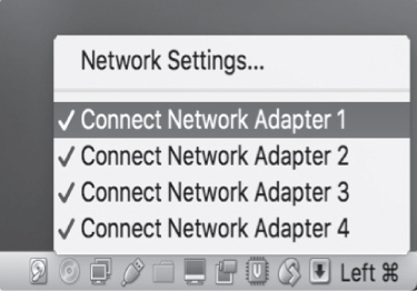
Figure 3.13 VirtualBox interface to disable a virtual network link.
Note that for the above example we disabled the transport security mechanism (TLS/DTLS) in the configuration file to make it easier to spy the traffic with Wireshark.
3.9.3 Avoiding Head‐of‐Line Blocking
Head‐of‐line blocking is a situation where transport protocol level retransmissions delay the delivery of all subsequent messages until the retransmitted message gets through. As mentioned in Section 3.9.2, RFC 6733 Section 2.1.1 has detailed language for handling of head‐of‐line blocking [24] in the Diameter message delivery. In the case of Diameter's use of TCP transport, there is no way of avoiding head‐of‐line blocking. It could be argued that a clever use of the multiple connection instances between two Diameter peers could be used to mimic the multiple transport streams feature of SCTP and work around issues caused by the head‐of‐line blocking that way.
In the case of SCTP, there are two ways to solve head‐of‐line blocking: use of multiple streams or use of the out‐of‐order delivery feature of the SCTP. RFC 3588 recommended using multiple streams and disabling out‐of‐order message delivery. Ideally, if each Diameter application between two peers used its own streams, then possible retransmissions at the transport level would not interfere with other applications, only the one experiencing lost packets. The problem with this approach is that both ends of the transport connection had to agree on the number of streams to use (the number of streams may be different in uplink and downlink directions). Unfortunately many implementations chose the easy way out by supporting only a single stream, which effectively makes SCTP behave like TCP when it comes to head‐of‐line blocking.
RFC 6733, on the other hand, recommends using a single stream but enabling the out‐of‐order message delivery. In this way messages sent after the “message in retransmission” can bypass it and thus avoid head‐of‐line blocking. The use of out‐of‐order message delivery can have a rare downside during the establishment of a peer connection. If the peer that received the CER message sends to the connection initiator an application message immediately after sending the CEA, it is possible for the application message to arrive before the CEA. Since the connection initiator is in WAIT‐I‐ACK state, the reception of the non‐CEA message will cause the initiator to error and close the transport connection (see Figure 3.12 in Section 3.8.2 ). A similar race condition may happen when a DPR is sent immediately after an application message. Due to possible message reordering, the peer may receive the DPR before the application message, and the application message is discarded before processing (the received peer state machine being in the CLOSING state).
There are multiple ways of mitigating the issues caused by reordering. First, stick with ordered delivery of SCTP messages and use a single stream instead of multiple streams. Second, if out‐of‐order delivery is still desired, then use small delays in the above‐mentioned message sequences (e.g., wait a small amount of time before sending a DPR after sending an application message). Third, switch the out‐of‐order delivery off in situations where there are known issues. All these can be categorized as hacks, though.
3.9.4 Multiple Connection Instances
Although we have said earlier that there is only one peer connection between two Diameter nodes, Diameter has a concept of multiple connection instances. This allows two Diameter peers to have any number of transport connections between them with a precondition that both ends support the feature. Furthermore, RFC 6733 says in Section 2.1:
A given Diameter instance of the peer state machine MUST NOT use morethan one transport connection to communicate with a given peer,unless multiple instances exist on the peer, in which case aseparate connection per process is allowed.
The above text indicates multiple instances of the Diameter node process also exist (we could also say that multiple threads of the Diameter node exist). The text refers to the UNIX way of forking client and server processes, i.e., using fork() to create a new client or server instance of the node with its own peer table entry. Obviously the client side (i.e., the connection initiator) has to bind the transport connection socket to a new source port before attempting a connection to the remote peer, otherwise the connection attempt will fail. On the server side, the connection receiver has to implement the arriving connection logic so that when the new instance is created and the connection is accepted, the new peer table entry state machine starts from the CLOSED state instead of whatever state the Diameter node “instance” may be in at that time, otherwise according to the peer state machine (see Section 3.8.2 , Figure 3.12) the incoming connection is rejected. This implies that the peer table is not searched for existing entries with the same Host Identity found in the arriving CER's Origin‐Host AVP when a new transport connection is established. The key here to make multiple instances to work is that each peer transport connection pair needs to have their own instance of peer control block (PCB) with its respective peer state machines.
Figure 3.14 illustrates how TCP connections can be used to realize multiple connection instances between two peers. Typically the transport connections are between one IP address pair. However, a DiameterIdentity may resolve to multiple IP addresses and that can be used when creating multiple connection instances also. When multiple IP addresses are used, the connection initiator can reuse the same source port number for its transport connections. These are implementation details, though.

Figure 3.14 Relations between realm tables, peer tables, application, and peer control blocks in a case of multiple connection instances.
To summarize, the following has to be supported by both Diameter peers for the multiple connection instances to work:
- Both the transport connection initiator (client) and the receiver (server) have to support the feature.
- The connection initiator has to originate the transport connection from a different source port than any existing and established transport connection between the Diameter peers. This requirement can be relaxed if the originator DiameterIdentity resolves to multiple IP addresses and each new “multiple connection instance” connection uses a different source IP address.
- The connection initiator must create a new peer table entry whose peer state machine starts from the CLOSED state.
- The connection receiver has to skip the peer table lookup for an existing peer table entry for the same Host Identity as found in the incoming CER
Origin‐HostAVP. - The connection receiver needs to create a new peer table entry for the new connection and start from the peer state machine CLOSED state.
RFC 6733 is silent on how multiple connection instances are handled from the routing and forwarding point of view. How the Diameter node implementation selects the peer connection to originate or forward messages is left for the implementation. In the case of multiple connection instances, the routing table would point to multiple peer table entries and the peer table would have multiple entries with the same remote peer Host Identity.
Multiple connection instances are unlikely to improve transport level reliability, because each instance exchanges IP packets between the same source and destination IP pair, thus using the same network path. However, multiple instances could be used for host internal load balancing, assuming the new instances are instantiated in a new CPU core or on a blade in a cluster, or similar. Since the multiple connection instances behavior is somewhat underspecified in RFC 6733, it is likely that proper “out of box” interoperability would be challenging to achieve between Diameter implementations.
References
- 1 J. Veizades, E. Guttman, C. Perkins, and S. Kaplan. Service Location Protocol. RFC 2165, Internet Engineering Task Force, June 1997.
- 2 M. Mealling and R. Daniel. The Naming Authority Pointer (NAPTR) DNS Resource Record. RFC 2915, Internet Engineering Task Force, Sept. 2000.
- 3 A. Gulbrandsen, P. Vixie, and L. Esibov. A DNS RR for specifying the location of services (DNS SRV). RFC 2782, Internet Engineering Task Force, Feb. 2000.
- 4 P. Mockapetris. Domain names – implementation and specification. RFC 1035, Internet Engineering Task Force, Nov. 1987.
- 5 S. Thomson, C. Huitema, V. Ksinant, and M. Souissi. DNS Extensions to Support IP Version 6. RFC 3596, Internet Engineering Task Force, Oct. 2003.
- 6 M. Jones, J. Korhonen, and L. Morand. Diameter Straightforward‐Naming Authority Pointer (S‐NAPTR) Usage. RFC 6408, Internet Engineering Task Force, Nov. 2011.
- 7 M. Mealling. Dynamic Delegation Discovery System (DDDS) Part One: The Comprehensive DDDS. RFC 3401, Internet Engineering Task Force, Oct. 2002.
- 8 L. Daigle and A. Newton. Domain‐Based Application Service Location Using SRV RRs and the Dynamic Delegation Discovery Service (DDDS). RFC 3958, Internet Engineering Task Force, Jan. 2005.
- 9 J. Korhonen, H. Tschofenig, J. Bournelle, G. Giaretta, and M. Nakhjiri. Diameter Mobile IPv6: Support for Home Agent to Diameter Server Interaction. RFC 5778, Internet Engineering Task Force, Feb. 2010.
- 10 M. Cotton, L. Eggert, J. Touch, M. Westerlund, and S. Cheshire. Internet Assigned Numbers Authority (IANA) Procedures for the Management of the Service Name and Transport Protocol Port Number Registry. RFC 6335, Internet Engineering Task Force, Aug. 2011.
- 11 T. Berners‐Lee, R. Fielding, and L. Masinter. Uniform Resource Identifier (URI): Generic Syntax. RFC 3986, Internet Engineering Task Force, Jan. 2005.
- 12 D. Crocker and P. Overell. Augmented BNF for Syntax Specifications: ABNF. RFC 2234, Internet Engineering Task Force, Nov. 1997.
- 13 C. Rigney, S. Willens, A. Rubens, and W. Simpson. Remote Authentication Dial In User Service (RADIUS). RFC 2865, Internet Engineering Task Force, June 2000.
- 14 C. Finseth. An Access Control Protocol, Sometimes Called TACACS. RFC 1492, Internet Engineering Task Force, July 1993.
- 15 P. Hoffman, A. Sullivan, and K. Fujiwara. DNS Terminology. RFC 7719, Internet Engineering Task Force, Dec. 2015.
- 16 J. Postel. Transmission Control Protocol. RFC 0793, Internet Engineering Task Force, Sept. 1981.
- 17 R. Stewart. Stream Control Transmission Protocol. RFC 4960, Internet Engineering Task Force, Sept. 2007.
- 18 T. Dierks and E. Rescorla. The Transport Layer Security (TLS) Protocol Version 1.2. RFC 5246, Internet Engineering Task Force, Aug. 2008.
- 19 E. Rescorla and N. Modadugu. Datagram Transport Layer Security Version 1.2. RFC 6347, Internet Engineering Task Force, Jan. 2012.
- 20 A. Jungmaier, E. Rescorla, and M. Tuexen. Transport Layer Security over Stream Control Transmission Protocol. RFC 3436, Internet Engineering Task Force, Dec. 2002.
- 21 K. Jiao and G. Zorn. The Diameter Capabilities Update Application. RFC 6737, Internet Engineering Task Force, Oct. 2012.
- 22 R. Stewart, Q. Xie, M. Tuexen, S. Maruyama, and M. Kozuka. Stream Control Transmission Protocol (SCTP) Dynamic Address Reconfiguration. RFC 5061, Internet Engineering Task Force, Sept. 2007.
- 23 A. Ford, C. Raiciu, M. Handley, and O. Bonaventure. TCP Extensions for Multipath Operation with Multiple Addresses. RFC 6824, Internet Engineering Task Force, Jan. 2013.
- 24 B. Aboba and J. Wood. Authentication, Authorization and Accounting (AAA) Transport Profile. RFC 3539, Internet Engineering Task Force, June 2003.