
Chapter 1
Introducing Microcontrollers and the BASIC Stamp
In This Chapter
![]() Looking at microcontrollers and how they work
Looking at microcontrollers and how they work
![]() Examining the BASIC Stamp microcontroller
Examining the BASIC Stamp microcontroller
![]() Building simple BASIC Stamp projects
Building simple BASIC Stamp projects
You can make a circuit board do almost anything you like using a computer with a parallel printer port and a bit of software, as you discover in Book VI, Chapter 4. But sometimes you want to dispense with that ugly, bulky PC and the wires running from it to your amazing electronic invention. For example, perhaps you’d prefer not to have to use a computer just to run some Christmas lights or you want to free your walking, talking robot from the reins of the PC. That’s where microcontrollers such as the BASIC Stamp come into the picture.
In a nutshell, a microcontroller is a small computer on a single chip, which you can purchase for £25 or less. This chapter introduces you to microcontrollers in general, and describes the fundamentals of using the BASIC Stamp microcontroller in particular, one of the most popular models available today. In Chapters 2 to 4 of this minibook, we go into more details about using the BASIC Stamp microcontroller, including how to write the programs that control its operation.
 You can buy many other different kinds of microcontrollers as well. We choose to work with the BASIC Stamp for this minibook primarily because its programming language is easier to pick up and use than the languages of other types of microcontrollers. As an added plus, you can purchase a BASIC Stamp Starter Kit for around £100, making the BASIC Stamp an easy and affordable way to discover microcontrollers.
Meeting the Mighty Microcontroller
In essence, a microcontroller is a complete computer on a single chip. Like all computer systems, microcontrollers consist of several basic subsystems, all interconnected together, but starting at its heart with:
![]() Central processing unit (CPU): The brains of the microprocessor. A CPU carries out the instructions provided to it by a program. The CPU can do basic arithmetic as well as other operations necessary to the proper functioning of the computer, such as moving data from one location of memory to another or receiving data as input from the outside world.
Central processing unit (CPU): The brains of the microprocessor. A CPU carries out the instructions provided to it by a program. The CPU can do basic arithmetic as well as other operations necessary to the proper functioning of the computer, such as moving data from one location of memory to another or receiving data as input from the outside world.
The CPU of a microcontroller is usually much simpler than the CPU found in a desktop computer, but it’s conceptually very similar. In fact, the CPUs found in many modern microcontrollers are as advanced as the CPUs used in desktop computers only a few years ago.
![]() Clock: Drives the CPU and other components of the microcontroller by providing timing pulses that control the pacing of program instructions as they’re executed one at a time by the CPU. For most microcontrollers, the clock ticks along at a pace of a few million ticks per second. In contrast, the clock that drives a typical desktop computer ticks along at a few billion ticks per second.
Clock: Drives the CPU and other components of the microcontroller by providing timing pulses that control the pacing of program instructions as they’re executed one at a time by the CPU. For most microcontrollers, the clock ticks along at a pace of a few million ticks per second. In contrast, the clock that drives a typical desktop computer ticks along at a few billion ticks per second.
![]() Random access memory (RAM): Provides a scratchpad area where the computer can store the data on which it’s working. For example, if you want the computer to determine the result of a calculation (such as 2 + 2), you need to provide a location in the RAM where the computer can store the result.
Random access memory (RAM): Provides a scratchpad area where the computer can store the data on which it’s working. For example, if you want the computer to determine the result of a calculation (such as 2 + 2), you need to provide a location in the RAM where the computer can store the result.
In a desktop computer, the amount of available RAM is measured in billions of bytes (GB for gigabytes). In a microcontroller, the RAM is often measured just in bytes. That’s right: not billions (GB), millions (MB; megabytes) or even thousands (KB; kilobytes) of bytes, but plain old bytes. For example, the popular BASIC Stamp 2, which we use in this chapter and throughout this minibook, has a total of 32 bytes of RAM.
![]() EEPROM: A special type of memory that holds the program that runs on a microcontroller.
EEPROM: A special type of memory that holds the program that runs on a microcontroller.
 EEPROM stands for Electrically Erasable Programmable Read-Only Memory, but that’s not on the test!
EEPROM is read-only, which means that when data has been stored in EEPROM, a program running on the microcontroller’s CPU can’t change it. However, you can write data to EEPROM memory by connecting the EEPROM to a computer via a USB port. Then, the computer can send data to the EEPROM.
In fact, this process is how you program microcontrollers. You use special software on a PC to create the program that you want to run on the microcontroller. Then, you connect the microcontroller to the PC and transfer the program from the PC to the microcontroller. The microcontroller then executes the instructions in the program.
Most microcontrollers have a few thousand bytes of EEPROM memory, which is enough to store relatively complicated programs downloaded from a PC.
One of the most important features of EEPROM memory is that it doesn’t lose its data when you turn off the power. Thus, after you transfer a program from a PC to a microcontroller’s EEPROM, the program remains in the microcontroller until you replace it with another program. You can turn the microcontroller off and put it away in a cupboard for years, and when you turn the microcontroller back on, the program recorded years ago runs again.
![]() I/O pins: A vitally important feature, which enables the microcontroller to communicate with the outside world. Although some microcontrollers have separate input pins and output pins, most have shared I/O pins that can be used for input and output.
I/O pins: A vitally important feature, which enables the microcontroller to communicate with the outside world. Although some microcontrollers have separate input pins and output pins, most have shared I/O pins that can be used for input and output.
I/O pins normally use the basic Transistor-Transistor Logic (TTL) interface that we describe in Chapter 3 of Book VI: high (logic 1) is represented by +5 V (volts) and low (logic 0) is represented by 0 V.
 Most microcontrollers can handle only a small amount of current directly through the I/O pins: 20–25 milliamperes (mA) is typical and is enough to light up a light-emitting diode (LED). But for circuits that require more current you need to isolate the higher current load from the microcontroller I/O pins, usually with a transistor driver.
Working with the BASIC Stamp
The BASIC Stamp is a microcontroller, made by Parallax, which is an essentially complete, self-contained computer system. Depending on the model, the Stamp (as it’s usually called) can be a single chip or a small circuit board.
The key feature that sets BASIC Stamp microcontrollers apart from others is that they include a built-in programming language called PBASIC (Parallax’s modified version of BASIC). This programming language makes creating programs that run on the Stamp easy. With most other microcontrollers, programming is much more difficult because you have to write the programs in a more complicated programming language.
Introducing the BASIC Stamp 2 Module
Figure 1-1 shows one of the more popular BASIC Stamps, called the BASIC Stamp 2 Module. This model is a complete computer system on a 24-pin DIP (dual inline package) that you can solder directly to a circuit board or (more likely) insert into a 24-pin DIP socket.

Figure 1-1: A BASIC Stamp 2 Module.
Here are the basic specifications for the BASIC Stamp 2 microcontroller (check out the earlier section ‘Meeting the Mighty Microcontroller’ for descriptions and roles of the various microprocessor parts):
![]() Clock speed: 20 MHz
Clock speed: 20 MHz
![]() Current draw: 3 mA
Current draw: 3 mA
![]() EEPROM: 2,048 bytes
EEPROM: 2,048 bytes
![]() Maximum I/O pin current: 20 mA
Maximum I/O pin current: 20 mA
![]() Number of I/O pins: 16
Number of I/O pins: 16
![]() Power supply: 5.5–15 V
Power supply: 5.5–15 V
![]() RAM: 32 bytes
RAM: 32 bytes
On the fourth item in the checklist, note that a limit applies to the total amount of current the I/O pins combined can handle: 40 mA for the first group of 8 I/O pins and another 40 mA for the second group.
We show you how to work with the BASIC Stamp 2 microcontroller throughout this chapter and the others in this minibook.
Buying a BASIC Stamp
Although you can purchase a BASIC Stamp microcontroller by itself, the easiest way to get into BASIC Stamp programming is to buy a starter kit that includes a BASIC Stamp along with the software that runs on your PC for programming it and the USB cable that connects your PC to the Stamp. In addition, most starter kits come with a prototype board that makes designing and testing simple circuits that interface with the Stamp pretty easy.
One such starter package is the BASIC Stamp Activity Kit, which you can purchase for around £130 from one of the UK distributors listed by Parallax on its website (www.parallax.com). This kit comes with the following components, which are pictured in Figure 1-2, and which I list here in order of importance:
![]() BASIC Stamp HomeWork board: A prototyping board that includes a BASIC Stamp 2 microcontroller, a small solderless breadboard, a clip for a 9 V battery and a connector for the USB programming cable (see the following section for more details on the HomeWork board).
BASIC Stamp HomeWork board: A prototyping board that includes a BASIC Stamp 2 microcontroller, a small solderless breadboard, a clip for a 9 V battery and a connector for the USB programming cable (see the following section for more details on the HomeWork board).
![]() USB cable: Connects the HomeWork board to a computer so that you can program the Stamp.
USB cable: Connects the HomeWork board to a computer so that you can program the Stamp.
![]() Useful electronic components: Includes resistors, LEDs, capacitors, a seven-segment display, pushbuttons, a potentiometer and plenty of jumper wires, for building circuits that connect to the Stamp.
Useful electronic components: Includes resistors, LEDs, capacitors, a seven-segment display, pushbuttons, a potentiometer and plenty of jumper wires, for building circuits that connect to the Stamp.
![]() Servo: A fancy motor that the Stamp can control.
Servo: A fancy motor that the Stamp can control.
![]() Instruction book: What’s a Microcontroller? gives a detailed overview of programming the BASIC Stamp 2.
Instruction book: What’s a Microcontroller? gives a detailed overview of programming the BASIC Stamp 2.

Figure 1-2: The BASIC Stamp Activity Kit.
Working with the BASIC Stamp HomeWork board
Figure 1-3 shows the BASIC Stamp HomeWork board. The chips near the centre of this board constitute the BASIC Stamp 2 module. On the left is a battery clip to which you can connect a 9 V battery for power. On the right is a small solderless breadboard, consisting of 17 rows of solderless connectors.
Immediately to the left of the breadboard is a row of 16 connectors that provide access to the 16 I/O pins of the BASIC Stamp 2, and immediately above the breadboard is a row of connectors that provide access to +5 V (identified as Vdd and Vin on the board) and ground (identified as Vss). This breadboard is designed to allow you to construct simple circuits that connect to the 16 I/O pins. You can connect pushbuttons and other devices that send input to the program running on the Stamp or LEDs or other output equipment that the Stamp program can control.

Figure 1-3: The BASIC Stamp HomeWork board.
Choosing the Board of Education
You can construct all the projects that we describe in this minibook on the BASIC Stamp HomeWork board. But if you want to create more elaborate projects, you may want to consider using an alternative called the Board of Education, as shown in Figure 1-4. This board costs about the same as the HomeWork board but provides a few additional handy features. In particular, the Board of Education includes the following:
![]() A prototype board similar to the one on the HomeWork board.
A prototype board similar to the one on the HomeWork board.
![]() A special 20-pin connector that allows you to connect external circuits permanently to the BASIC Stamp’s 16 I/O pins – which is useful if you want to build circuits that are more permanent than the solderless breadboard allows.
A special 20-pin connector that allows you to connect external circuits permanently to the BASIC Stamp’s 16 I/O pins – which is useful if you want to build circuits that are more permanent than the solderless breadboard allows.
![]() Special connectors for I/O pins 12, 13, 14 and 15 that are designed to connect the BASIC Stamp to servos (motors).
Special connectors for I/O pins 12, 13, 14 and 15 that are designed to connect the BASIC Stamp to servos (motors).
![]() A 9 V battery clip and an external power connector that allow you to power the BASIC Stamp with a 9 V battery or an external power supply.
A 9 V battery clip and an external power connector that allow you to power the BASIC Stamp with a 9 V battery or an external power supply.
![]() A removable 24-pin BASIC Stamp 2 Module, which allows you to use the Board of Education to program the Stamp. When you’re certain that the program is working properly, you can remove the BASIC Stamp 2 Module from the Board of Education and plug it into your own circuit.
A removable 24-pin BASIC Stamp 2 Module, which allows you to use the Board of Education to program the Stamp. When you’re certain that the program is working properly, you can remove the BASIC Stamp 2 Module from the Board of Education and plug it into your own circuit.
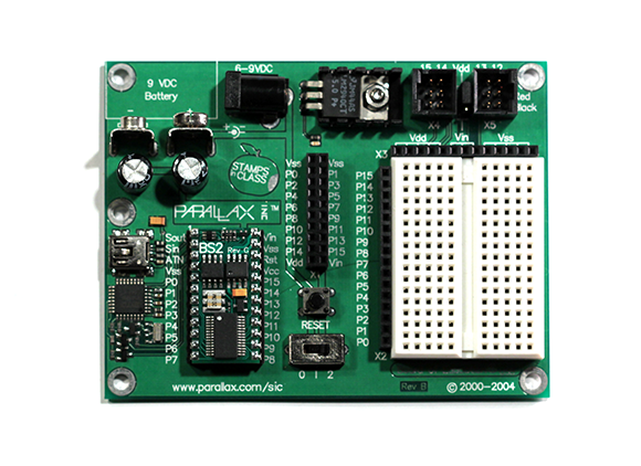
Figure 1-4: The Board of Education.
Connecting to BASIC Stamp I/O pins
Before you start writing programs to run on a BASIC Stamp, you have to build the circuit(s) that you’re going to connect to the I/O pins on the Stamp. When the circuit is constructed, you can then write a program that controls the circuits you’ve connected to each pin.
The BASIC Stamp 2 has a total of 16 separate I/O pins, which means that you can connect as many as 16 separate circuits. These 16 I/O circuits are more than enough for most BASIC Stamp projects.
For now, start with a basic circuit that simply connects an LED to one of the Stamp’s output pins. The program that you write and load onto a Stamp can turn each of the 16 I/O pins on (high) or off (low) by using simple programming commands. When an I/O pin is high, +5 V is present at the pin. When it’s low, no voltage is present.
 Each I/O pin can handle as much as 20 mA of current, and altogether they can handle up to 40 mA which is more than enough to light an LED. As with any LED circuit, you need to provide a current-limiting resistor in the circuit. If you forget to include this resistor, you destroy the LED and possibly fry the Stamp too – so always be sure to include the current-limiting resistor. A 470Ω resistor is usually appropriate for LED circuits connected to Stamp I/O pins.
Figure 1-5 shows a simple schematic diagram for a circuit that drives an LED from pin 15 of a BASIC Stamp. Notice in this schematic that the pin output is represented by a simple five-sided shape (to the left of the figure). Commonly, schematics do not draw the Stamp as a single rectangle as you would for other integrated circuits. Instead, each I/O connection in the circuit is shown using a connector shape.

Figure 1-5: Schematic for an LED circuit connected to a BASIC Stamp I/O pin.
Figure 1-6 shows how you can build this circuit on a BASIC Stamp HomeWork board. Notice that the resistor is inserted into the P15 connection and the sixth hole in the second row. The LED’s anode is inserted in the seventh hole in row 2, and the cathode is in one of the Vss connectors. Project 1-2, which appears in the later section ‘Flashing an LED with a BASIC Stamp’, walks you through creating this circuit.

Figure 1-6: Assembling an LED circuit on a BASIC Stamp HomeWork board.
Installing the BASIC Stamp Windows Editor
The BASIC Stamp Windows Editor is the software that you use on your computer to create programs that can be downloaded to a BASIC Stamp microcontroller. This software is available free from the Parallax website (www.parallax.com).
The easiest way to find the right page from which you can download the software is to use an Internet search engine to search for ‘BASIC Stamp Windows Editor’.
Or you can download the software by opening a web browser such as Internet Explorer, going to www.parallax.com and following these instructions:
1. Click the Resources tab.
2. Click Downloads in the menu on the left side of the page.
3. Click BASIC Stamp Software.
4. Select the version of the software for your computer and download and install the software.
After you’ve installed the software, run it by choosing BASIC Stamp Editor from the Windows Start menu. Figure 1-7 shows how the editor appears when you first run it.

Figure 1-7: The BASIC Stamp Windows Editor.
Connecting to a BASIC Stamp
Before you can use the Stamp Editor to program a BASIC Stamp, you need to connect the Stamp to your computer and then configure the Stamp Editor so that it can communicate with the Stamp. The following steps describe the procedure for doing that with a BASIC Stamp HomeWork board. The procedure for connecting a Board of Education (which we describe in the earlier section ‘Choosing the Board of Education’) is very similar, and so you’ll have no trouble following it if you have a Board of Education instead of a HomeWork board:
1. Insert a 9 V battery in the HomeWork board.
You see a green LED light up on the board when the battery is inserted. If this light doesn’t come on check the battery, because it may be dead.
2. Plug the USB-to-serial adapter into the DB9 connector on the HomeWork board.
This step is necessary because the HomeWork board uses an older-style serial connector to connect to your computer, but most computers don’t have serial ports. The adapter converts the serial port connection on the HomeWork board to a USB port.
Figure 1-8 shows how the HomeWork board appears with the USB-to serial adapter plugged in.

Figure 1-8: The HomeWork board with the USB-to-serial adapter connected.
3. Plug the smaller end of the USB cable into the USB-to-serial adapter and the larger end into an available USB port on your computer.
After a moment, your computer chirps happily to acknowledge the presence of the BASIC Stamp. A pop-up bubble may appear informing you that Windows is installing the driver needed to access the device. If so, just wait for the bubble to disappear.
In addition to the activity on your computer, you can also notice a green LED on the USB-to-serial adapter, indicating that the adapter is powered up and ready to adapt.
4. In the BASIC Stamp Editor, choose Run⇒Identify.
Doing so brings up the Identification window, as shown in Figure 1-9.

Figure 1-9: Identifying your BASIC Stamp.
This window indicates that your BASIC Stamp 2 is connected. If it doesn’t, consult the ‘Connection Troubleshooting’ section of the Stamp Editor’s Help command (Help⇒BASIC Stamp Help).
5. Click Close to dismiss the Identification window.
6. You’re done and ready to write your first BASIC Stamp program!
Here are a couple of points to know about connecting a BASIC Stamp to the Stamp Editor:
![]() If you're having trouble connecting, the most likely cause (other than a loose connection or forgetting to insert the battery) is an incorrect driver for the USB-to-serial adapter. To install the right driver software, take a look at
If you're having trouble connecting, the most likely cause (other than a loose connection or forgetting to insert the battery) is an incorrect driver for the USB-to-serial adapter. To install the right driver software, take a look at http://www.parallax.com/usbdrivers. Follow the instructions that appear on that page to install the correct driver.
![]() Parallax makes a version of the Board of Education that has a USB port directly on the board. If you’re using that board instead of the HomeWork board, you don’t need a USB-to-serial adapter. Instead, you can plug the USB cable directly into the Board of Education.
Parallax makes a version of the Board of Education that has a USB port directly on the board. If you’re using that board instead of the HomeWork board, you don’t need a USB-to-serial adapter. Instead, you can plug the USB cable directly into the Board of Education.
Writing Your First PBASIC Programs
If you’ve never done any form of computer programming before, you’re in for a fun and fascinating adventure, during which you can find out more about how computers work.
Discovering programming basics
In a nutshell, a computer program is a set of written instructions that a computer knows how to read, interpret and carry out. The instructions are written in a language that humans and computers can read. They aren’t quite English, but they resemble English enough that English-speaking people can understand what they mean. (Of course, non-English programming languages are also available, but PBASIC happens to be an English-based programming language.)
Computer programs are stored in text files that consist of one or more lines of written instructions. In most cases, each line of the computer program contains one instruction. Each instruction tells the computer to do something specific, such as add two numbers together or make one of the output pins go high.
The trick of computer programming is to put the right instructions together in the right sequence to get the program to do exactly what you want it to do. Of course, to do that, you need to have a solid understanding of what you want the program to do and a knowledge of the variety of instructions that are available. The PBASIC programming language consists of about 70 different types of instructions. But don’t be discouraged; you can write useful programs using only a handful of these commands.
Saying ‘Hello World’
Pretty much the most basic computer program is called Hello World. This simple program displays the text string 'Hello, World!' to demonstrate what a simple program looks like.
In PBASIC (the official name of the BASIC language that’s used on BASIC Stamps), the Hello World program consists of three lines:
' {$STAMP BS2}
' {$PBASIC 2.5}
DEBUG "Hello, World!"
The first two lines are called directives. They don’t tell the BASIC Stamp to do anything as such; instead, they provide information that the Stamp Editor needs to know to prepare your program so that it can be downloaded to the Stamp. The first line indicates that the microcontroller on which you’re going to run the program is a BASIC Stamp 2 (BS2). The second line indicates that this program uses version 2.5 of PBASIC for this program (the current version).
Every program you write must include these two lines. Fortunately, you don’t have to type them yourself. Instead, you can use menu commands or toolbar buttons to insert the directives automatically:
![]()
![]() Directive⇒Stamp⇒BS2: Inserts the
Directive⇒Stamp⇒BS2: Inserts the $STAMP BS2 directive to indicate that you're using BASIC Stamp 2.
![]()
![]() Directive⇒PBASIC⇒Version 2.5: Inserts the
Directive⇒PBASIC⇒Version 2.5: Inserts the $PBASIC 2.5 directive to indicate that you're using version 2.5 of PBASIC.
The third line of the Hello World program is the only line that tells the BASIC Stamp to do something. This command, called DEBUG, tells the BASIC Stamp to send a bit of text to the computer connected via the USB port. The DEBUG command always consists of two parts: the word 'DEBUG' followed by text that must be enclosed in quotation marks. For example:
DEBUG "Hello, World!"
This line sends the message ‘Hello, World!’ to your computer. The message is displayed in a window called the Debug Terminal window within the Stamp Editor.
Running the Hello World program
Project 1-1 shows you how to run the Hello World program on a HomeWork board. Figure 1-10 shows the resulting output as displayed in the Debug Terminal window.

Figure 1-10: The Debug Terminal window displays the output from the Hello World program.


Flashing an LED with a BASIC Stamp
A BASIC Stamp is serious overkill for a circuit that simply flashes an LED on and off: you can do that for a few quid with a 555 timer IC, a capacitor and a couple of resistors (as we describe in Book III, Chapter 2). But discovering how to flash an LED on and off with a BASIC Stamp is an important step towards completing more complex projects.
To flash an LED, you first have to connect an LED to an output pin in such a way that the Stamp can turn the LED on by taking the output pin high. You find out how to do that earlier in this chapter, in the section ‘Connecting to BASIC Stamp I/O Pins’. So all that remains is discovering how to write a PBASIC program that flashes the LED.
To write the program, you need to know the following five PBASIC instructions:
![]()
HIGH: Sets one of the Stamp's I/O pins to high. You use this instruction to turn the LED on.
![]()
LOW: Sets one of the Stamp's I/O pins to low. You use this instruction to turn the LED off.
![]()
PAUSE: Causes the Stamp to sit idle for a specified period of time. You use this instruction to delay the program a bit between high and low commands so that the LED stays on for a while before you turn it off, and then stays off for a while before you turn it back on.
![]()
GOTO: Causes the program to loop back to a previously designated location. You use this instruction to cause the program to flash the LED on and off repeatedly, instead of flashing it on and off only once.
![]()
Label: Marks the location that you want the GOTO statement to loop to.
Here’s the complete program that flashes the LED:
' {$STAMP BS2}
' {$PBASIC 2.5}
Main:
HIGH 15
PAUSE 1000
LOW 15
PAUSE 1000
GOTO Main
Take a look at how this program works, one line at a time:
|
Program Line |
What It Does |
|
|
Indicates that the program runs on a BASIC Stamp 2. |
|
|
Indicates that the program uses version 2.5 of PBASIC. |
|
|
Creates a label named Main that marks the location that the GOTO command loops back to. |
|
|
Makes I/O pin 15 high, which turns the LED on. |
|
|
Pauses the program for 1,000 milliseconds (ms), which is the same as one second, and allows the LED to stay on for one full second. |
|
|
Makes I/O pin 15 low, which turns the LED off. |
|
|
Pauses the program for 1,000 ms, which allows the LED to stay off for one full second. |
|
|
Makes the program skip back to the Main label, which causes the program to loop through the HIGH, PAUSE, LOW and PAUSE instructions over and over again. |
The net effect of this program is that the LED on pin 15 flashes on and off at one-second intervals.
Project 1-2 describes building a simple circuit that connects an LED to pin 15 and runs the LED Flasher program so that the LED flashes on and off. The completed circuit for this project is shown in the earlier Figure 1-6.

