
Chapter 2
Getting Logical
In This Chapter
![]() Discovering Boolean logic
Discovering Boolean logic
![]() Examining the different types of logic gates
Examining the different types of logic gates
![]() Building logic circuits with only NAND or NOR gates
Building logic circuits with only NAND or NOR gates
![]() Stimulating logic gates with software
Stimulating logic gates with software
Mr Spock doesn’t just stand out in Star Trek because of his pointy ears. His uniqueness is also due to what’s between them: his brain. His part Vulcan ancestry makes him colder and less emotional than the rest of the Starship Enterprise crew. Spock thinks like a computer, because they both employ a lot of logic.
In this chapter, we look at the basic principles of logic, which are the underpinnings of digital electronics. In particular, we explore logic gates, which (rather than being Bill’s daughter!) are handy devices that perform a logical operation on one or more binary inputs and produce a single binary output result (we describe binary in this minibook’s Chapter 1).
The overwhelming complexity of modern computer systems is built on the simple concept of logic gates. A modern computer processor consists of millions of individual logic gates connected in a way that enables the processor to perform complicated operations at amazing speed.
In this chapter we ask you to think a little like Mr Spock, as we investigate Boolean logic and how you can employ logic gates to great effect. Are you ready to boldly go (split infinitive and all)?
Introducing Boolean Logic and Logic Gates
 In digital electronics, Boolean logic refers to the manipulation of binary values in which a 1 represents the concept of true and a 0 represents the concept of false. In electronic circuits that implement logic, binary values are represented by voltage levels. In the most common convention, a binary value of 1 is represented by +5 V (also called high) and a binary 0 is represented by 0 V (also called low).
Logical operations (also called logical functions) are functions that can be applied to one or more logic inputs and produce a single logic output. One of the most common types of logic operations is NOT, which simply inverts the state of its input. In other words, with the NOT operation, if the input is true, the output is false; if the input is false, the output is true.
A gate is a circuit or device that implements a logical function. Thus, a NOT gate is a circuit or device that implements the logical NOT operation. NOT gates are very common in digital circuits.
You can create gate switches in a variety of ways. The most common method uses transistors as switches, arranged in such a way that the correct output is generated based on the logical inputs and the type of gate being implemented. In Chapter 3 of this minibook, you see how gates are implemented, but in this chapter we discuss what the various types of gates do and how you can combine them in real-world circuits.
Regardless of the method used to create gate circuits, all logic circuits depend on different voltage ranges to represent 1 (by approximately +5 V, or high) and 0 (by approximately 0 V, or low).
Entering Through the Different Types of Logic Gates
In this section, we look at seven of the most common types of logic gates – NOT, AND, OR, NAND, NOR, XOR and XNOR – plus a theorem that combines two gates. All these gates except NOT use at least two inputs; the NOT gate has just one input. To help you get your bearings, Table 2-1 provides a brief overview of these gate types.
Table 2-1 Most Common Types of Logic Gates
|
Gate |
Description |
|
NOT |
Inverts the input (high becomes low, low becomes high) |
|
AND |
Outputs high if all the inputs are high; otherwise, outputs low |
|
OR |
Outputs high if at least one of the inputs is high; otherwise, outputs low |
|
NAND |
Outputs high if all the inputs are low; otherwise, outputs low |
|
NOR |
Outputs high if at least one of the inputs is low; otherwise, outputs low |
|
XOR |
Outputs high if one, and only one, of the inputs is high; otherwise, outputs low |
|
XNOR |
Outputs high if one, and only one, of the inputs is low; otherwise, outputs low |
Noting NOT gates
The simplest of all gates is the NOT gate, which is also called an inverter. A NOT gate has just one input, and its output is the opposite of the input. If the input is low, the output is high. If the input is high, the output is low.
Table 2-2 shows the truth table of an inverter. A truth table is simply a table that lists every possible combination of input values and shows the resulting output for each combination. For an inverter, the truth table is simple. Only one input exists and so only two possibilities exist: the input is low or it’s high. As you can see in the table, the output is simply the opposite of the input.
 In truth tables, a common convention is to use 0s and 1s to represent logic values rather than the terms high and low.
Table 2-2 Truth Table for an Inverter
|
Input |
Output |
|
0 |
1 |
|
1 |
0 |
Figure 2-1 shows the standard logic symbol for a NOT gate. Symbols such as this one are often used in schematic diagrams for circuits that use gates. The NOT symbol is simply a triangle with the input at one end and the output at the other. The small circle on the output is called a negation bubble, which indicates that the output is inverted.
![]()
Figure 2-1: Symbol for a NOT gate.
Appraising AND gates
A two-input AND gate is a gate with two inputs and one output. The output is high only if both the inputs are high. Any other combination of inputs results in the outputs being low. Table 2-3 shows the truth table for an AND gate with two inputs.
Table 2-3 Truth Table for a Two-Input AND Gate
|
Input A |
Input B |
Output |
|
0 |
0 |
0 |
|
0 |
1 |
0 |
|
1 |
0 |
0 |
|
1 |
1 |
1 |
Figure 2-2 shows the standard symbol for an AND gate. The inputs are on the left and the output is on the right.
![]()
Figure 2-2: Symbol for a two-input AND gate.
You can create AND gates with more than two inputs. For each additional input that you add to a gate, the number of possible input combinations doubles: a two-input gate has 4 possible input combinations; a three-input gate has 8 possible combinations; a four-input gate has 16 possible input combinations and so on.
Table 2-4 shows the truth table for a three-input AND gate. As you can see, the output is high only if all the inputs are high. Any other combination of inputs produces low output.

You can combine gates in a circuit to create logic networks that are more complicated than a single gate can produce. For example, you create a three-input AND gate by using two two-input AND gates as shown in Figure 2-3. In the figure, the first AND gate produces a high output only if the inputs A and B are true. Then the output of the first AND gate is used as one of the inputs to the second AND gate; the other input is the input C.
 Thinking outside the gate
You can think of an AND gate as being a form of multiplication. Consider that when you multiply any quantity of single-bit binary numbers, only two possible results exist: 0 or 1. Look at the truth tables in Tables 2-3 and 2-4, and try multiplying the binary inputs in each row. In each case, the answer is 0 for any combination that contains a 0 in any of the inputs. The answer is 1 only if all the inputs are 1.

Figure 2-3: You can use a pair of two-input AND gates to create a logic network that operates like a three-input AND gate.
Because the output of the second gate is high only if both its inputs are high, and because the first input to the second gate is the output from the first gate (high only if both its inputs are high), the output of the entire circuit (designated as X) is high only if all three inputs (A, B and C) are high.
Figure 2-4 shows how AND gates can be used in a home-alarm system. Here, the inputs for the various sensors placed on the home’s doors and windows are processed by the sensor circuit, which sends a high signal to one of the inputs of the AND gate if any of the sensors indicates an intrusion anywhere in the house. Then the arming circuit sends a 1 to the other input of the AND gate if the system is armed. Finally, the alarm circuit sounds an audible alarm if the AND gate’s output is 1. As a result, the alarm sounds if an intrusion is detected and the system is armed.
When used in this way, an AND gate is often called an enable input, because one of the inputs to the AND gate enables the other input to be processed. When the enable input is high, the controlled input is allowed to pass through the AND gate. When the enable is low, the controlled input is inhibited.

Figure 2-4: An AND gate used in a home-alarm system.
Figure 2-5 shows a more developed version of the home-alarm system, which uses an enable input. Here, the alarm doesn’t sound immediately when an intrusion is detected. Instead, the alarm sounds 30 seconds after it’s triggered, giving you time to disable the alarm before waking up the neighbours. When the sensor circuit detects an intrusion, it sends a trigger pulse to a 555 timer circuit, which then generates a 30-second high pulse. The high signal from the 555 timer output is routed through a NOT gate, which inverts the signal to low. The low signal is sent to one of the inputs of the second AND gate. The other input to the second AND gate is the output of the first AND gate, which indicates that an intrusion has been detected, and the system is armed.
For the first 30 seconds after the intrusion is detected, the first input to the second AND gate is low and the second input is high, so that the output from the second AND gate is low. Thus, the alarm doesn’t sound. In effect, the timer output inhibits the alarm from sounding. But when the output from the 555 timer circuit goes low after the 30-second pulse ends, the NOT gate inverts the signal, sending a high output to the second AND gate. This situation causes the second AND gate’s output to go high, and so the alarm sounds. Thus, the inverted pulse from the timer circuit enables the alarm circuit.

Figure 2-5: An AND gate used as an enable input.
Observing OR gates
An OR gate produces a high output if any of the inputs is high. The output from an OR gate is low only if all the inputs are low. Table 2-5 shows the truth table for a two-input OR gate.
In an OR gate, how many of the inputs are high doesn’t matter. If at least one input is high, the output is high. Thus, in a two-input OR gate, the output is high if either input is high or both inputs are high. In a three-input OR gate, the output is high if any one, any two or all three of the inputs are high.
Table 2-5 Truth Table for a Two-Input OR Gate
|
Input A |
Input B |
Output |
|
0 |
0 |
0 |
|
0 |
1 |
1 |
|
1 |
0 |
1 |
|
1 |
1 |
1 |
Figure 2-6 shows the standard symbol for an OR gate, with inputs on the left and output on the right.
![]()
Figure 2-6: Symbol for a two-input OR gate.
Like AND gates, OR gates with more than two inputs are easy to create. No matter how many inputs the OR gate has, the output is high if any of the inputs is high.
Multiple-input OR gates are simple to create by combining two input OR gates. Figure 2-7 shows a logic network with three OR gates, effectively acting like a four-input OR gate: if any of the four inputs is high, the output is high.
You can combine two-input OR gates in a circuit to create OR networks that have more than two inputs. For example, Figure 2-8 shows how OR gates can be used in the sensor circuit of a home-alarm system with more than two inputs. In this circuit, eight separate alarm sensors are fed into a network of OR gates. If any one of the inputs is high, the output from the sensor circuit is high.

Figure 2-7: Three OR gates used to create a four-input OR gate.

Figure 2-8: OR gates used in a sensor circuit.
The sensor circuit uses seven OR gates to create an eight-input OR gate. Take a close look at the way the OR gates are arranged in this network to make sure that you understand how it works. Each of the eight inputs is routed to one of the four OR gates in the first tier of gates. These four OR gates reduce the eight inputs to four outputs, which are then sent to the two OR gates in the second tier. These two OR gates reduce their four inputs to two outputs, which are sent to the final OR gate. Then the output of the last OR gate becomes the output of the entire sensor circuit.
Looking at NAND gates
A NAND gate is a combination of an AND gate and a NOT gate. In fact, the name NAND is a contraction of NOT and AND. As you can see in Table 2-6, the output of a NAND gate is low when both the inputs are high. Otherwise, the output of the NAND gate is high.
Table 2-6 Truth Table for a Two-Input NAND Gate
|
Input A |
Input B |
Output |
|
0 |
0 |
1 |
|
0 |
1 |
1 |
|
1 |
0 |
1 |
|
1 |
1 |
0 |
Figure 2-9 shows the standard symbol for a NAND gate. This symbol is the same as the symbol for an AND gate (see the earlier Figure 2-2), with the addition of a circle at the output. As in the symbol for a NOT gate (check out the earlier Figure 2-1), the circle indicates that the output is inverted. In other words, a NAND gate is an AND gate whose output is inverted.
![]()
Figure 2-9: Symbol for a two-input NAND gate.
The NAND gate is special because you can use various combinations of NAND gates to create AND, OR or NOT gates. Thus, a logic network that consists of a combination of NOT, AND and OR gates can be created with an equivalent combination of just NAND gates. For this reason, the NAND gate is called a universal gate. To discover more about this characteristic of NAND gates, check out the ‘Using universal NAND gates’ section later in this chapter.
Another interesting thing about the NAND gate is that it can be used as a kind of OR gate (see the preceding section) that tests for low inputs instead of high inputs. In other words, the output of a NAND gate is high when either of the inputs is low.
This characteristic of NAND gates is useful in many situations. For example, consider the alarm sensor circuit in the preceding section and in Figure 2-8. Suppose that all the alarm sensors produce a high signal without an intrusion, and then go low following an intrusion. In the real world, many alarm sensors work exactly in this way. For instance, a sensor that detects whether a door is open is essentially a simple switch that’s closed when the door is closed and open when the door is open. When the door is closed, current flows through the switch and the signal from the sensor is high. When the door is opened, current stops flowing and the signal from the sensor goes low.
Figure 2-10 shows how you can use NAND gates to test for a low input on any of eight sensors. This circuit is identical to the circuit in the earlier Figure 2-8, except that all the OR gates have been replaced by NAND gates.

Figure 2-10: NAND gates used in a sensor circuit.
Checking out NOR gates
A NOR gate is a combination of an OR gate and a NOT gate (see the earlier sections ‘Observing OR gates’ and ‘Noting NOT gates’). As with NAND in the preceding section, the name NOR is a contraction of NOT and OR.
Table 2-7 shows the truth table for a NOR gate. As you can see, the output of a NOR gate is low when any of its inputs are high. Otherwise, the output of the NAND gate is high.
Table 2-7 Truth Table for a Two-Input NOR Gate
|
Input A |
Input B |
Output |
|
0 |
0 |
1 |
|
0 |
1 |
0 |
|
1 |
0 |
0 |
|
1 |
1 |
0 |
As Figure 2-11 shows, the standard symbol for a NOR gate is the same as the symbol for the OR gate in Figure 2-6, with a negation circle added to the output. The circle simply indicates that the output is inverted.
![]()
Figure 2-11: Symbol for a two-input NOR gate.
Like the NAND gate, the NOR gate is a universal gate. You can recreate any logic network that consists of NOT, AND and OR gates with just NOR gates. For more information, see the later section ‘Combining universal NOR gates’.
Just as a NAND gate is like an OR gate for low inputs, a NOR gate is like an AND gate for low inputs. In other words, the output of the NOR gate is high when both the inputs are low.
Figure 2-5, earlier in this chapter, shows an alarm circuit that sounds an alarm 30 seconds after an input sensor detects an intrusion. In that circuit, the output pulse from a 555 timer circuit is inverted by a NOT gate and then sent to an AND gate, which sends a high output to an audible alarm circuit when the output from a sensor circuit is high and when the 30-second timer pulse ends.
Figure 2-12 shows a version of the same circuit, which uses a NOR gate instead of an AND gate to feed the audible alarm circuit. In this circuit, the alarm sounds when the output from the sensor circuit is low and the output from the timer circuit is also low. You don’t need a NOT gate for the 555 timer output, but you do require a NOT gate on the output from the AND gate to invert its signal, so that it emits low when the system is armed and the alarm is tripped.

Figure 2-12: NOR gate used in a sensor circuit.
Going over XOR and XNOR gates
We cover two gate types in this section: XOR, which stands for Exclusive OR, and XNOR, which stands for Exclusive NOR.
In an XOR gate, the output is high if one, and only one, of the inputs is high. If both inputs are low or both are low, the output is low. Table 2-8 contains the truth table for an XOR gate.
Table 2-8 Truth Table for a Two-Input XOR Gate
|
Input A |
Input B |
Output |
|
0 |
0 |
0 |
|
0 |
1 |
1 |
|
1 |
0 |
1 |
|
1 |
1 |
0 |
Here’s another way to explain an XOR gate: the output is high if the inputs are different; if the inputs are the same, the output is low.
The XOR gate has a lesser-known cousin called the XNOR gate. An XNOR gate is an XOR gate whose output is inverted. Table 2-9 lists the truth table for an XNOR gate.
Table 2-9 Truth Table for a Two-Input XNOR Gate
|
Input A |
Input B |
Output |
|
0 |
0 |
1 |
|
0 |
1 |
0 |
|
1 |
0 |
0 |
|
1 |
1 |
1 |
Figure 2-13 shows the symbols used for XOR and XNOR gates. As you can see, the only difference between these two symbols is that the XNOR has a circle on its output to indicate that the output is inverted.

Figure 2-13: Symbols for two-input XOR and XNOR gates.
One of the most common uses for XOR gates is to add two binary numbers. For this operation to work, the XOR gate has to be used in combination with an AND gate, as shown in Figure 2-14.

Figure 2-14: You can use an XOR gate and an AND gate to add two binary numbers.
To help understand how the circuit shown in Figure 2-14 works, we review briefly how binary addition works:

If you want, you can write the results of each of the preceding addition statements by using two binary digits:

When results are written with two binary digits, as in this example, you can easily see how to use an XOR and an AND circuit in combination to perform binary addition. If you consider just the first binary digit of each result, you notice that it looks just like the truth table for an AND circuit (see Table 2-3) and that the second digit of each result looks just like the truth table for an XOR gate (in Table 2-8).
The adder circuit shown in Figure 2-14 has two outputs. The first is called the Sum and the second is called the Carry. The Carry output is important when several adders are used together to add binary numbers that are longer than 1 bit.
Diving into De Marvellous De Morgan’s Theorem
The logic concept De Morgan’s Theorem was created by Augustus De Morgan, a 19th-century British mathematician who developed many of the concepts that make Boolean logic work. In fact De Morgan’s theorem comprises two related theorems that have to do with how NOT gates are used in conjunction with AND and OR gates:
![]() An AND gate with inverted output behaves the same as an OR gate with inverted output behaves the same as an OR gate with inverted inputs.
An AND gate with inverted output behaves the same as an OR gate with inverted output behaves the same as an OR gate with inverted inputs.
![]() An OR gate with inverted output behaves the same as an AND gate with inverted output behaves the same as an AND gate with inverted inputs.
An OR gate with inverted output behaves the same as an AND gate with inverted output behaves the same as an AND gate with inverted inputs.
An AND gate with inverted output is also called a NAND gate, of course, and an OR gate with inverted output is also called a NOR gate. Thus, De Morgan’s laws can also be stated as follows:
![]() A NAND gate behaves the same as an OR gate with inverted inputs.
A NAND gate behaves the same as an OR gate with inverted inputs.
![]() A NOR gate behaves the same as an AND gate with inverted inputs.
A NOR gate behaves the same as an AND gate with inverted inputs.
An OR gate with inverted inputs is called a negative OR gate and an AND gate with inverted inputs is called a negative AND gate.
In case you’re not persuaded, review for a moment the truth table for a NAND gate:
|
A |
B |
X |
|
0 |
0 |
1 |
|
0 |
1 |
1 |
|
1 |
0 |
1 |
|
1 |
1 |
0 |
Now look at the truth table for an OR gate, with an extra set of columns added to show the inverted inputs:

Here, the A and B columns represent the inputs. The NOT A and NOT B columns are the inputs after they’ve been inverted. Finally, the X column represents an OR operation applied to the NOT A and NOT B values.
As you can see, the final output column of these truth tables is the same. Thus, a NAND gate is equivalent to a negative OR gate.
Any time you see a NAND gate in a circuit diagram, you can substitute a negative OR gate.
Now take a look at the other side of De Morgan’s Theorem. Here’s a truth table for a NOR gate:
|
A |
B |
X |
|
0 |
0 |
1 |
|
1 |
0 |
0 |
|
0 |
1 |
0 |
|
1 |
1 |
0 |
And here’s the output of a negative AND gate:
|
A |
B |
NOT A |
NOT B |
X |
|
0 |
0 |
1 |
1 |
1 |
|
0 |
1 |
1 |
0 |
0 |
|
1 |
0 |
0 |
1 |
0 |
|
1 |
1 |
0 |
0 |
0 |
Again, you can see that these two truth tables give the same output.
Just as a circle is used on the output of a NAND or NOR gate to indicate that the output is inverted, you can use a circle on the inputs to an OR or AND gate to indicate that the inputs are inverted. Figure 2-15 shows these symbols. The figure also shows that the negative OR and AND gates are interchangeable with the NAND and NOR gates.

Figure 2-15: NAND and NOR gates are equivalent to negative OR and AND gates.
Understanding that All You Need is NAND (or NOR)
In ‘Looking at NAND gates’ earlier in this chapter, we mention that the NAND gate is a universal gate because any other type of gate (such as AND, OR, XOR and XNOR) can be constructed solely from combinations of NAND gates.
This fact is incredibly useful, because it enables you to build any logic circuit, simple or complex, by using just NAND gates. When you begin to construct your own digital circuits, you can stock up on integrated circuits that contain just NAND gates safe in the knowledge that you can build even the most complex circuits with your stock of NAND gates.
Also, in the earlier section ‘Checking out NOR Gates’, we reveal that the NOR gate is a universal gate, too. Thus, you can also build any logic circuit by using nothing but NOR gates.
In the following sections, we explain how you can use NAND and NOR gates to build other types of gates.
Using universal NAND gates
Figure 2-16 shows how you can use NAND gates in various combinations to create NOT, AND, OR and NOR gates (which we explain in the earlier section ‘Entering Through the Different Types of Logic Gates’).

Figure 2-16: Creating NOT, AND, OR and NOR gates using nothing but NAND gates.
The following list describes how the circuits work:
![]() NOT: You can create a NOT gate from a NAND gate simply by tying the two inputs of the NAND gate together (we describe a project using this technique in Chapter 5 of this minibook). Because the two inputs of the NAND gate are tied together, only two input combinations are possible: both high or both low. If both inputs are high, the NAND gate outputs a low. If both inputs are low, the NAND gate outputs high. Thus, the circuit behaves exactly as a NOT gate.
NOT: You can create a NOT gate from a NAND gate simply by tying the two inputs of the NAND gate together (we describe a project using this technique in Chapter 5 of this minibook). Because the two inputs of the NAND gate are tied together, only two input combinations are possible: both high or both low. If both inputs are high, the NAND gate outputs a low. If both inputs are low, the NAND gate outputs high. Thus, the circuit behaves exactly as a NOT gate.
![]() AND: You can create an AND gate by using two NAND gates. The first NAND gate does what NAND gates do: returns low if both inputs are high and returns high if both inputs are anything else. The second NAND gate is configured as a NOT gate to invert the output from the first NAND gate.
AND: You can create an AND gate by using two NAND gates. The first NAND gate does what NAND gates do: returns low if both inputs are high and returns high if both inputs are anything else. The second NAND gate is configured as a NOT gate to invert the output from the first NAND gate.
One of the basic rules of NOT gates is that if you invert a signal twice, you end up with the same signal. If the original input is high, and you invert it, the signal becomes low. Invert the input again, and it returns to high. With this rule in mind, you can see how the two NAND gates work together to create an AND gate.
![]() OR: You need three NAND gates to create an OR gate. You use a pair of NAND gates configured as NOT gates to invert the two inputs. Then the third NAND gate produces a low output if both the original inputs are low. If one of the original inputs is high, or if both the original inputs are high, the output of the third gate is high.
OR: You need three NAND gates to create an OR gate. You use a pair of NAND gates configured as NOT gates to invert the two inputs. Then the third NAND gate produces a low output if both the original inputs are low. If one of the original inputs is high, or if both the original inputs are high, the output of the third gate is high.
![]() NOR: You need four NAND gates to create a NOR gate. As you can see in Figure 2-16, this circuit is the same as the OR gate circuit, with the addition of another NOT gate to invert the output from the third NAND gate. Inverting the output changes the overall function of the circuit from OR to NOR.
NOR: You need four NAND gates to create a NOR gate. As you can see in Figure 2-16, this circuit is the same as the OR gate circuit, with the addition of another NOT gate to invert the output from the third NAND gate. Inverting the output changes the overall function of the circuit from OR to NOR.
Combining universal NOR gates
Like NAND, NOR is a universal gate. Figure 2-17 shows how you can combine NOR gates in various ways to create NOT, AND, OR and NAND gates.
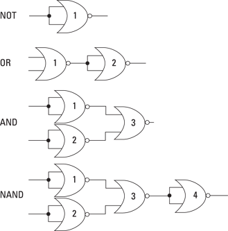
Figure 2-17: Creating NOT, OR, AND and NAND gates using nothing but NOR gates.
Here’s how the circuits work:
![]() NOT: Creating a NOT gate from a NOR gate is the same as creating a NOT gate from a NAND gate: you simply tie the two inputs of the NOR gate together (see the preceding section). If both inputs are low, the NOR gate outputs a high. Otherwise, the output is low.
NOT: Creating a NOT gate from a NOR gate is the same as creating a NOT gate from a NAND gate: you simply tie the two inputs of the NOR gate together (see the preceding section). If both inputs are low, the NOR gate outputs a high. Otherwise, the output is low.
![]() OR: You need two NOR gates to create an OR gate. The first NOR gate returns low if either input is high or both inputs are high. The second NOR gate is configured as a NOT gate to invert the output of the first NOR gate.
OR: You need two NOR gates to create an OR gate. The first NOR gate returns low if either input is high or both inputs are high. The second NOR gate is configured as a NOT gate to invert the output of the first NOR gate.
![]() AND: You need three NOR gates to create an AND gate. The first two are configured as NOT gates, and so they invert the inputs. The third NOR gate produces a high output if both the original inputs are high.
AND: You need three NOR gates to create an AND gate. The first two are configured as NOT gates, and so they invert the inputs. The third NOR gate produces a high output if both the original inputs are high.
![]() NAND: You require four NOR gates to create a NAND gate. The first three NOR gates are configured just as they are for an AND gate. Then a fourth NOR gate configured as a NOT gate inverts output from the third NOR gate.
NAND: You require four NOR gates to create a NAND gate. The first three NOR gates are configured just as they are for an AND gate. Then a fourth NOR gate configured as a NOT gate inverts output from the third NOR gate.
Playing with Gates in Software
One of the best ways of finding out how logic gates work is to download one of the many software logic gate simulators that are available free on the Internet. You can find these programs by firing up your search engine and searching for keywords such as ‘logic gate simulator’.
One of our favourite programs is Logic Circuit Designer, written by Ivan Andrei. You can download it from http://download.cnet.com/Logic-Circuit-Designer/3000-2054_4-10840569.html. Figure 2-18 shows this useful program in action.

Figure 2-18: Using the Logic Circuit Designer program to simulate logic circuits on your computer.
Here are just a few of the features of the Logic Circuit Designer program:
![]() You can add AND, OR, NOT, XOR, NAND, NOR and XNOR gates to your
circuit simply by dragging them from a toolbar.
You can add AND, OR, NOT, XOR, NAND, NOR and XNOR gates to your
circuit simply by dragging them from a toolbar.
![]() You can connect the gate inputs and outputs by clicking an input or
output and then dragging it to another gate input or output.
You can connect the gate inputs and outputs by clicking an input or
output and then dragging it to another gate input or output.
![]() You can add simple switches to the circuit for external inputs.
You can add simple switches to the circuit for external inputs.
![]() You can add LEDs at any point in the circuit to indicate the status of an
output or an input.
You can add LEDs at any point in the circuit to indicate the status of an
output or an input.
Noting Notations
You can show input and output variables in the following different ways:
![]() If an input, we’ll call it A, is changed by a NOT gate, the inverted output is represented by A with a short line or bar over the top, like this: Ā.
If an input, we’ll call it A, is changed by a NOT gate, the inverted output is represented by A with a short line or bar over the top, like this: Ā.
![]() The AND operation is sometimes shown with a dot between two variables. So, if the input variables are A and B, the output is A.B, but the
dot is sometimes left out so you could also see it shown as just AB.
The AND operation is sometimes shown with a dot between two variables. So, if the input variables are A and B, the output is A.B, but the
dot is sometimes left out so you could also see it shown as just AB.
![]() The OR operation is sometimes shown as a plus sign, like this: A+B = Q.
The OR operation is sometimes shown as a plus sign, like this: A+B = Q.