Chapter 3
Working with Infrared
In This Chapter
![]() Transmitting information with infrared light
Transmitting information with infrared light
![]() Spotting infrared light
Spotting infrared light
![]() Making infrared light
Making infrared light
![]() Building proximity detector projects
Building proximity detector projects
In this chapter, we describe working with circuits that produce and detect the invisible light that’s commonly called infrared.
Infrared light has all sorts of applications for wireless communication, the most common of which is the remote control for your television. Other uses for infrared include night-vision goggles and cameras as well as temperature detection.
Have fun!
Introducing Infrared Light
Infrared light is light whose frequency is just below the range of visible red light. Specifically, infrared is light whose frequency falls between 1 and 400 THz (1 THz is 1 trillion cycles per second). The infrared spectrum falls right between microwaves and visible light.
As we discuss in Chapter 1 of this minibook, an inverse relationship exists between frequency and wavelength: the lower the frequency, the longer the wavelength. If you describe infrared in terms of its wavelength rather than its frequency, infrared waves are longer than the waves of visible light, but shorter than microwaves. The wavelength of infrared light is between 0.75 and 300 microns (a millionth of a metre). Thus, at the very bottom edge of the infrared spectrum, the infrared waves are about one-third of a millimetre long. At the upper end, the waves are about one thousandth of a millimetre long. If the waves get any shorter than that, they become visible light.
Figure 3-1 shows the entire spectrum of electromagnetic radiation, so that you can see where infrared falls within the grand scheme of things radiation-wise.

Figure 3-1: Infrared light falls between visible light and microwaves.
Infrared light isn’t visible to human eyes. Perhaps Mother Nature thinks that we don’t need to look at things in infrared, which is too bad because more than half of all the light energy emitted from the sun is in the form of infrared light. If human eyes could see infrared light as well as the visible light, sunny days would seem twice as bright.
 Sometimes infrared light is confused with heat, because humans can’t see infrared light waves but can feel them in the form of heat. In other words, infrared light waves heat surfaces that absorb them. Visible light has this effect too, which is why you feel cooler in the shade than in the sun. Because heat is an effect of infrared light, infrared light can be used as a heat source. But infrared light and heat aren’t the same thing.
Infrared light is often used to detect objects that humans can’t see in visible light. One common application of this ability is night vision. According to a principal of physics called Planck’s law, all matter emits electromagnetic radiation if its temperature is above absolute zero. Some of that radiation is in the infrared spectrum, and so devices that can detect infrared light can literally see in the dark.
To enhance the effect, some night-vision devices illuminate an area with infrared light. Because the human eye can’t see the infrared light, the area illuminated still appears dark, but to a detector sensitive to infrared light, the area is lit up and fully visible.
A remote history
The first wireless remote control was developed by Zenith in 1955. It used ordinary visible light to turn the TV on or off and to change channels, but it had one nasty defect: you had to position your television in the room so that light from an outside source (such as the setting sun shining through a window) didn’t hit the light sensor. Otherwise, the TV may shut itself off right in the middle of the evening news when the sun reached just the right angle and hit the sensor.
Today remotes use complicated encoding schemes to avoid such random misfirings. You’re probably familiar with the procedure you have to go through when programming a remote control to work with a particular television. This programming is necessary because no widely accepted standard exists for how the codes on a remote control should work, and so each manufacturer uses its own encoding scheme.
Another common application of infrared light is for wireless communications across short distances. The best known infrared devices are television remote controls. These units contain a bright infrared light source and the television itself includes an infrared detector. When you point the remote control at the television and push a button, the remote control turns on the infrared light source and encodes a message on it. The receiver picks up this signal, decodes the message and does whatever the message directs it to do – turns up the volume, changes the channel and so on.
 Like visible light, solid objects can block infrared light and it can bounce off reflective objects. That’s why the remote doesn’t work when your cat is standing between you and the television. But it’s also why you can get around your cat by pointing the remote at a window. The infrared waves bounce off the glass and, if the angle is right, arrive at the television.
Detecting Infrared Light
You can detect infrared light in an electronic circuit in several different ways, but the most common is with a device called a phototransistor. You can buy a phototransistor for less than a pound at any shop that stocks electronic components.
To understand how a phototransistor works, think about the workings of a transistor. As we describe in Book II, Chapter 6, a transistor has three terminals: the base, collector and emitter. A path exists within the transistor between the collector and emitter. How well this path conducts depends on whether voltage is applied across the base and the emitter. If voltage is applied, the collector-emitter path conducts well. If no voltage is on the base, the collector-emitter path doesn’t conduct.
In a phototransistor, the base isn’t a separate terminal connected to a voltage source in your circuit. Instead, the base is exposed to light. When infrared light hits the base, the energy in the light is converted to voltage and the emitter-collector path conducts.
 Thus, infrared light hitting the base has the same effect as voltage on the base of a traditional transistor: the infrared light turns the transistor on. The brighter the infrared light, the better the emitter-collector path conducts.
Figure 3-2 shows a simple circuit that uses an infrared phototransistor to detect infrared light. When infrared light is present, the collector-emitter circuit conducts and the LED lights up. Thus, the LED lights when the phototransistor is exposed to infrared light.

Figure 3-2: A simple infrared detector circuit.
Project 3-1 describes how to build this circuit on a solderless breadboard and Figure 3-3 shows the assembled circuit.
When you’ve assembled this circuit, try exposing the phototransistor to different light sources to see whether they emit infrared light. One sure source of infrared is your TV remote control. Point the remote at the phototransistor and press any button on it. You see the LED flash on and off quickly as it responds to the infrared signals being sent by the remote.
 Another interesting source of infrared is an open flame. Be very careful, of course; we don’t want you burning down your house just to see if the flames produce infrared light. If you have a small gas lighter, light it up and hold it near the phototransistor.

Figure 3-3: The assembled infrared detector circuit (Project 3-1).


Creating Infrared Light
The easiest way to create infrared light is by using a special light-emitting diode (LED) that operates in the infrared spectrum. Infrared LEDs (often called IR LEDs) are readily available at electronics parts shops.
IR LEDs are similar to regular LEDs, except that you can’t see the light they emit. The LED itself is usually a dark purple or blue colour. Like other LEDs, the cathode lead is shorter than the anode lead.
As with any LED, you have to use a resistor in series with an IR LED to prevent excess current from burning out the LED. To calculate the size of the resistor, you need to know three things:
![]() Supply voltage: For example, 9 V.
Supply voltage: For example, 9 V.
![]() LED forward-voltage drop: For most IR LEDs, the forward-voltage drop is 1.3 V.
LED forward-voltage drop: For most IR LEDs, the forward-voltage drop is 1.3 V.
![]() Desired current through the LED: Usually, the current flowing through the IR LED should be kept under 50 mA. However, IR LEDs are typically rated for more current than regular LEDs.
Desired current through the LED: Usually, the current flowing through the IR LED should be kept under 50 mA. However, IR LEDs are typically rated for more current than regular LEDs.
With these three facts to hand, you can calculate the correct resistor size by using Ohm’s law (which we describe in Book II, Chapter 2):
1. Calculate the resistor voltage drop.
Subtract the voltage drop of the IR LED (typically 1.3 V) from the total supply voltage. For example, if the total supply voltage is 9 V and the LED drops 1.3 V, the voltage drop for the resistor is 7.7 V.
2. Convert the desired current to amperes.
In Ohm’s law, you have to express the current in amperes. You can convert milliamperes to amperes by dividing the milliamperes by 1,000. Thus, if your desired current through the IR LED is 50 mA, you need to use 0.05 A in your Ohm’s law calculation.
3. Divide the resistor voltage drop by the current in amperes.
The result is the desired resistance in ohms. For example, if the resistor voltage drop is 7.6 V and the desired current is 50 mA, you need a 152 Ω resistor.
4. Choose a standard resistor size that’s close to the calculated resistance.
A 150 Ω resistor is close enough for a 9 V circuit. If you don’t have a 150 Ω resistor, a 220 Ω does the job just fine.
When you’ve chosen the correct resistor size, simply wire it in series with the IR LED, as shown in the schematic in Figure 3-4.

Figure 3-4: Use a current-limiting resistor to protect an IR LED.
Constructing Proximity Detectors
The combination of an IR LED and a photodiode is often used as a proximity detector, a gadget that detects when an object is nearby. You can build a proximity detector in two ways:
![]() Common-emitter proximity detector: Mount the IR LED and the phototransistor so that they face each other. The phototransistor detects the infrared light from the IR LED. If an object comes between the IR LED and the phototransistor, the light is blocked and the phototransistor turns off.
Common-emitter proximity detector: Mount the IR LED and the phototransistor so that they face each other. The phototransistor detects the infrared light from the IR LED. If an object comes between the IR LED and the phototransistor, the light is blocked and the phototransistor turns off.
![]() Common-collector proximity detector: Mount the IR LED and the IR photodiode next to each other facing the same direction. When an object comes near the IR LED, some infrared light bounces off the object and the phototransistor detects it and turns on.
Common-collector proximity detector: Mount the IR LED and the IR photodiode next to each other facing the same direction. When an object comes near the IR LED, some infrared light bounces off the object and the phototransistor detects it and turns on.
We show you how to build the two types of proximity detector circuits in the following two sections.
Building a common-emitter proximity detector
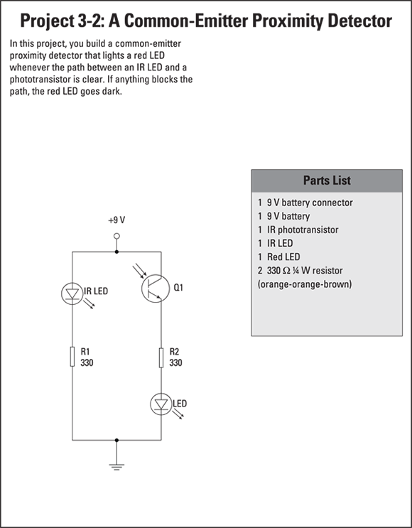
Figure 3-5 shows a schematic for a simple proximity circuit. Although it isn’t shown in the schematic, this circuit assumes that IR LED and Q1 are oriented so that Q1 can detect the infrared light emitted by IR LED, indirectly (for a proximity detector) or directly (for an interrupter).
This circuit is called a common-emitter circuit, because the phototransistor’s emitter is usually placed between the phototransistor side of the circuit and the output side of the circuit that’s connected to the IR LED. In a common-emitter circuit, the output voltage is on when the phototransistor detects infrared light. Thus, the red LED lights up when the path between the IR LED and phototransistor isn’t obstructed. If you block the path between the IR LED and phototransistor, the red LED goes dark.

Figure 3-5: A common-emitter proximity detector circuit.
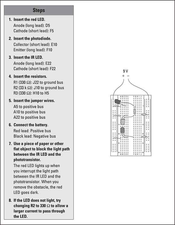
Project 3-2 shows you how to build this circuit configured as an interrupter and Figure 3-6 displays the finished project. When you connect this circuit to power, the red LED comes on. If you pass an object such as a piece of paper between the IR LED and the phototransistor, the red LED goes off.
The output in this circuit is simply a red LED, but you can just as easily connect the output to other circuit components. For example, the output can drive a mechanical relay if you want to use the proximity detector to turn on low voltage lights. Or you can connect the output to a digital logic circuit as we describe in Book VI, Chapter 4.

Figure 3-6: Using an IR LED and a phototransistor as a proximity detector (Project 3-2).

Building a common-collector proximity detector
Figure 3-7 shows a circuit that uses a common-collector circuit, in which the collector is the common point between the phototransistor circuit and the LED output circuit. When wired in this way, the LED is dark whenever the path between the IR LED and the phototransistor is clear. When something blocks the path and the phototransistor stops detecting infrared light, the red LED comes on.

Figure 3-7: A common-collector proximity detector circuit.
Project 3-3 shows how to build this circuit configured as an interrupter and Figure 3-8 shows the finished project. When you connect this circuit to power, the red LED stays dark. But if you pass an object between the IR LED and the phototransistor, the red LED turns on.
Practical applications for this type of circuit include triggers for intruder alarms or automatic opening catflaps, or any circuit that makes something happen in response to an object coming between two points.

Figure 3-8: This circuit lights a red LED when the path between an IR LED and a phototransistor is blocked (Project 3-3).