
Configuring Inter-VLAN Routing
In Chapter 14, “Configuring Switches,” you learned that when switches are configured with VLANs, hosts in different VLANs cannot communicate without the help of a router. Consider the router and switch in Figure 15.2.
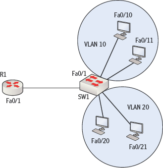
FIGURE 15.2 Inter-VLAN routing
SW 1 is configured with two VLANs: VLAN 10 and VLAN 20. The switch ports Fa0/20 and Fa0/21 have been added to VLAN 20. The switch ports Fa0/10 and Fa0/11 have been added to VLAN 10.
The computers connected to those switch ports will not be able to communicate with one another until inter-VLAN routing is configured on R1. The first step is to connect the router to the switch with a straight-through cable, connecting the Fa0/1 interface on the router to the Fa0/1 interface on the switch, as shown in Figure 15.2.
To configure the router to route between the VLANs, the following steps must be taken:
- Create a trunk link between the router and the switch and configure an encapsulation protocol on the trunk link.
- Create subinterfaces for each VLAN on the physical link.
These steps are explained in the following sections.
Creating a Trunk Link with Encapsulation
The link that exists between the switch and the router must be specified as a trunk link, because it will be carrying traffic from both VLAN 10 and VLAN 20. Starting on the switch end of the connection, at the interface configuration prompt for the Fa0/1 interface, two commands need to be executed. The first command is as follows:
SW1(config-if)switchport trunk encapsulation isl
This command instructs the router to set the interface as a trunk link and to use the Inter-Switch Link (ISL) encapsulation protocol. This is one of two trunking protocols available. The other is IEEE 802.1q. Either will work fine, but the same protocol must be set on both the switch end and the router end. Keep these factors in mind when you choose between the two:
- 802.1 q is an IEEE standard and works on all routers.
- ISL works on only Cisco devices.
When configuring the trunk link for 802.1q, the command is executed as follows: SWl(config-if) switchport trunk encapsulation dotlq.
The second command to execute on the switch will set the trunking mode of the interface to trunk, which will prevent it from acting in any other mode. This command is executed while still in interface configuration mode, as shown here:
SW1(config-if)switchport mode trunk
TRUNK MODES
Links can be set as either access or trunk (they default to access). But they can also be set to automatically negotiate with the other end of the link to become a trunk link under certain conditions. For example, the following command will set the link to become a trunk link if the other end requests that the link become a trunk link:
For more information on how this works, see this link: www.cisco.com/en/US/docs/switches/lan/catalyst3560/software/release/12.2_25_see/command/reference/cli3.html#wp1948171.
The router end of the connection must be set as a trunk link with the correct encapsulation as well. However, this step cannot be completed without first creating subinterfaces for each VLAN. The next section explains what subinterfaces are and how to configure them on the router.
Creating and Configuring Subinterfaces
When traffic from multiple VLANs will traverse the same physical connection, there must be some way to segregate the VLANs for the purpose of assigning a default gateway to each. Remember that VLANs create Network Access layer segmentation, but the devices will also need to be segregated at the Internet layer with IP subnets.
IP addresses are applied to interfaces on a router. Therefore, to apply two IP addresses (in different IP subnets) to the same physical interface, the interface must be logically subdivided. This is done with subinterfaces. Then one IP address (located in one IP subnet) can be applied to one subinterface, and another IP address (located in a different IP subnet) can be applied to the other subinterface.
When subinterfaces are created, they are named after the physical interface of which they are a part, and then a dot is added, followed by a number to identify the subinterface. For example, a subinterface of the Fa0/1 physical interface might be Fa0/1.1 or Fa0/1.2.
After the subinterface has been created, you will immediately be placed into subinterface configuration mode for that subinterface. While you are in that mode, you should do the following:
- Set the encapsulation type and associate the subinterface with a VLAN.
- Apply an IP address.
Before we get started, consider Figure 15.3. It has been labeled with the IP addresses that the computers in each VLAN will have and the IP address that will be applied to the router interface for each subinterface. There will be a sub-interface for each VLAN. Note that computers must be set with the IP address of the router subinterface that has been associated with the host's VLAN as their default gateway.
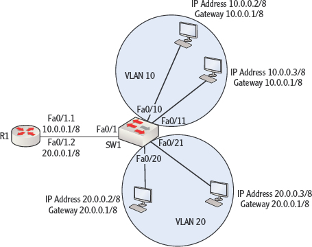
FIGURE 15.3 Subinterfaces and IP addresses
To create the first subinterface, execute the following command at the global configuration prompt on the router:
R1(config)#interface Fa0/1.1
R1(config-subif)#
Notice that the prompt changed, indicating that you are now in configuration mode for the subinterface Fa0/1.1. Now set the encapsulation to match what was set on the switch (ISL). The 10 that follows identifies the VLAN:
R1(config-subif)# encapsulation isl 10
Finally, set the IP address just as you would on any other interface:
R1(config-subif# ip address 10.0.0.1 255.255.255.0
The complete set of commands for the other subinterface is as follows:
R1(config)#interface Fa0/1.2
R1(config-subif)# encapsulation isl 20
R1(config-subif# ip address 20.0.0.1 255.255.255.0
Because the two networks are directly connected to the router, the routes will automatically be placed in the routing table of R1. Its table is shown here:
R1>show ip route
Codes: C - connected, S - static, I - IGRP, R - RIP, M - mobile, B - BGP
       <output omitted>

C 10.0.0.0/8 is directly connected, FastEthernet0/1.1
C 20.0.0.0/8 is directly connected, FastEthernet0/1.2
When a host in one of the VLANs needs to send something to a host in the other VLAN, the host will send the packet to its default gateway, which will be the IP address that was assigned to the subinterface associated with its VLAN. The router will then locate the network in its table and route the packet back out the interface to the VLAN on which the destination machine is located.
Cisco routers use routing tables to maintain the information required for them to direct the packets they receive to the proper destination. Routes can be placed into the routing table in one of two ways: static routing and dynamic routing. Entries are added to the routing table by using the ip route command. To verify the completion of the ip route command or the existence of a route in the routing table, the table can be viewed with the show ip route command. To configure a router to route between VLANs, you create a trunk link between the router and the switch, configure an encapsulation protocol on the trunk link, and create subinterfaces for each VLAN on the physical link.
ADDITIONAL EXERCISES
In this exercise, you will create static routes that link the networks in Figure 15.4. It assumes that you have connected three routers, as shown in the diagram. The interfaces must also be assigned the IP addresses as shown, and the interfaces should be enabled.
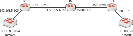
FIGURE 15.4 Static routing exercise
For router R1, perform these steps:
- Log into the router and access global configuration mode, as shown here:
R1>enab1e
R1>Password:  <enter password>
R1#config t
R1(config)#
- Use the ip route command to add the route to the 10.0.0.0/8 network with a next hop address of 172.0.16.5.1, which is the address of the next router (R2) on the path to R3:
R1(config)#ip route 10.0.0.0 255.0.0.0. 172.16.5.1
- Verify that the route is present in the table by backing out to user mode and executing the show ip route command. You should see an entry in the table, as shown in the following output.
R1>show ip route
Codes: C - connected, S - static, I - IGRP, R - RIP, M -
mobile, B - BGP
        <output omitted>
C    192.168.5.0 is directly connected, FastEthernet0/1
C    172.16.0.0 is directly connected, FastEthernet0/2
S    10.0.0.0/8 via 172.16.5.2
Note that for FastEthernet0/1 and FastEthernet0/2, your interface may be different.
For router R3, perform these steps:
- Log into the router and access global configuration mode, as shown here:
R3>enab1e
R3>Password:       <enter password>
R3#config t
R3(config)#
- Use the ip route command to add the route to the 192.168.5.0/24 network with a next hop address of 15.0.0.1/8, which is the address of the next router (R2) on the path to R1:
R3(config)#ip route 192.168.5.0 255.255.255.0 15.0.0.1
- Verify that the route is present in the table by backing out to user mode and executing the show ip route command. You should see an entry in the table, as shown in the following output.
R1>show ip route
Codes: C - connected, S - static, I - IGRP, R - RIP, M -
mobile, B - BGP
        <output omitted>
C    10.0.0.0 is directly connected, FastEthernet0/1
C    15.0.0.0 is directly connected, FastEthernet0/2
S    192.168.5.0/24 via 15.0.0.2
Note that for FastEthernet0/1 and FastEthernet0/2, your interface may be different.
REVIEW QUESTIONS
- Which of the following routes are placed into the routing table automatically?
- Network routes
- Host routes
- Directly connected routes
- Default routes
- Where is traffic sent if it does not have an existing route in the table?
- A network route
- A host route
- A directly connected route
- A default route
- Which of the following is an advantage of static routing?
- Reduced administrative effort required to create the routes
- Automatic reaction to outages and changes in the network
- Elimination of routing update traffic
- Reduction of routing update traffic
- In which of the following situations would static routing be advisable?
- The network topology is very large, changes rarely if ever occur, and the system is very stable.
- The network topology is very small, changes frequently occur, and the system is very stable.
- The network topology is very small, changes rarely if ever occur, and the system is very unstable.
- The network topology is very small, changes rarely if ever occur, and the system is very stable.
- What command is used to place routes into the routing table?
- ip route
- route add
- route
- insert route
- In the following command, what does the IP address 192.16835.6 represent?
R1(config)#ip route 150.0.0.0 255.0.0.0.0 192.168.5.6
- The address of the local exit interface
- The exit interface on the destination router
- The address of the next hop router in the path to the destination network
- The address of the destination host
- What command produced the following output?
Codes: I - IGRP derived, R - RIP derived, O - OSPF derived,
C - connected, S - static
<output omitted>
C   10.0.0.0 is directly connected, FastEthernet 0/1
C   192.168.5.0 is directly connected, FastEthernet 0/2
S   15.0.0.0/8 via 192.168.5.5
- show run
- show ip route
- show network
- show interfaces
- Which of the routes in the following table was manually added?
C  10.0.0.0 is directly connected, FastEthernet 0/1
C  192.168.5.0 is directly connected, FastEthernet 0/2
D  25.0.0.0/8 via 17.6.0.0
S  15.0.0.0/8 via 192.168.5.5
- 10.0.0.0
- 25.0.0.0/8
- 192.168.5.0
- 15.0.0.0/8
- Which of the following components is not required for inter-VLAN routing?
- A trunk link
- Subinterfaces
- An encapsulation protocol
- Multicast IP addresses
- Which of the following steps in configuring inter-VLAN routing is not done in subinterface configuration mode?
- Set the link to trunk
- Apply an IP address
- Associate the subinterface with a VLAN
- Set the encapsulation type