
Understanding and Managing the Boot Process
It's not enough to understand where everything is located on Cisco devices. To troubleshoot a device, it is critical to understand the boot process. There is a normal boot process and then there are actions you can take to alter the process. It is important to understand how to do that and in what situation doing so would be beneficial.
This section covers the boot process in detail. The output that you can expect to see at certain points in the boot process is described. This section also explains how to copy a Cisco IOS from a TFTP server, how to set a Cisco device to boot to a Cisco IOS located in a network location, and, finally, how to manage the startup and running configuration files referred to earlier in this chapter.
Understanding the Boot Process
The boot process can be broken down into the following steps:
- When a Cisco device starts, it first looks for instructions in the ROM chip, just as a computer will look for instructions in the BIOS chip. These instructions are independent of the Cisco IOS and will execute regardless of whether there is an IOS in flash. One of the first instructions executed is a power-on self-test (POST). All of the hardware and software contents are checked for functionality.
- The bootstrap program loads and is executed. You can tell this has happened when you see output on the screen describing the bootstrap version and information about the hardware described in the POST, as shown here:
System Bootstrap, Version 11.0(10c), SOFTWARE
 Copyright (c) 1986-1996 by Cisco Systems
 2500 processor with 6144 Kbytes of main
memory
 F3: 5593060+79544+421160 at 0×3000060
- Next the device looks in NVRAM for settings contained in the configuration register. In the upcoming sections, you will be introduced to the details of these settings and how to change them. For now, understand that the configuration register will tell the system what step to take next and what those steps could be:
- Boot to ROM Monitor (ROMmon) mode—This can be used to edit the startup configuration file on the device and to load another IOS image.
Both ROMmon and the ROM mini IOS are located on the ROM chip.
- Boot to the ROM IOS—This is a mini version of the IOS that can be used for a limited set of functions if the IOS is corrupted (such as to download another IOS image).
- Look for a startup configuration file in NVRAM
- Boot to ROM Monitor (ROMmon) mode—This can be used to edit the startup configuration file on the device and to load another IOS image.
- If the settings in this register are set to the default, the system will look next in NVRAM for a startup configuration file. This file is read because it could also contain instructions about the boot order. If there is no boot system command found in the startup configuration file, the system will begin a search for an IOS. It will search first in flash, and then it will look for a TFTP server, and if all else fails, it will boot into either ROMmon mode or the ROM mini IOS. When the image is found, the image name will appear on the screen, as in the following example:
Looking for a startup configuration in NVRAM is an alternate way to manage the boot process rather than using the configuration register.
Cisco Internetwork Operating System Software
 IOS ™ 2500 Software (C2500-I-L), Version 12.0(5)
 Copyright (c) 1986-1999 by cisco Systems, Inc.
 Compiled Tue 15-Jun-99 19:49 by phanguye
 Image text-base: 0x0302EC70, data-base: 0×0000100
- After the IOS becomes operational, it loads the startup configuration file located in NVRAM, if the file is present. After it is read, system messages will begin to appear on the screen as the settings (such as interfaces being enabled) are executed, as shown here:
00:00:22: %LINK-3-UPDOWN: Interface Ethernet0, changed state to up
 00:00:22: %LINK-3-UPDOWN: Interface Seria10, changed state to up
 00:00:22: %LINK-3-UPDOWN: Interface Seria11, changed state to up
 00:00:23: %LINEPROTO-5-UPDOWN: Line protocol on Interface
Ethernet0, changed state to up
 00:03:13: %LINK-5-CHANGED: Interface Seria10, changed state to
administratively down
 00:03:13: %LINK-5-CHANGED: Interface Seria11, changed state to
administratively down
- If the file is not found or if you have configured the device to ignore the file (using the configuration register settings), you will receive a menu-based set of prompts that will allow you to create one. You can choose to either use this method to create the file or answer no to the first question in the series, and the system will proceed on to the CLI interface. The first part of the setup menu is as follows:
--- System Configuration Dialog ---


At any point you may enter a question mark ‘?’ for help.

Use ctrl-c to abort configuration dialog at any prompt.

Default settings are in square brackets ‘[]’.


Continue with configuration dialog? [yes]:
- If a configuration file is found or if you answer no to the first question in the setup menu, the router will proceed to the CLI and you will see the following prompt:
Press RETURN to get started!
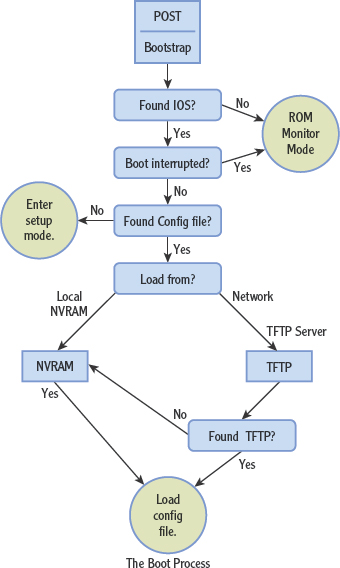
THE BOOT DECISION PROCESS
Here is a more visual representation of the boot decision process.
Managing the IOS
The Cisco IOS image file can be loaded from flash, which is the most common location, but it can also be loaded to the device from a TFTP server. This is a much slower way to load the IOS, but it does offer the benefit of maintaining the image for multiple routers in one location. Operations such as updates and image patches can then be managed in a central location and can help to maintain IOS image consistency across multiple devices.
To set the device to boot from an image located on a TFTP server, a command must be executed (boot system tftp://ip_address/fi1ename) and saved to the startup configuration file. When that file is read as indicated in step 3 of the boot process (as shown in the previous section), it will instruct the device to skip looking for the image in flash and proceed to load the image from a TFTP server. Because the command will also include the IP address of the TFTP server and the name of the image file on the server, it will greatly speed the process as the default TFTP location method will be broadcast for the TFTP server.
A more common use of a TFTP server is as a platform to transfer IOS images to the router and to store images for backup and maintenance. The TFTP server can be used to store startup configuration files as well. This offers the same benefits as does centrally locating IOS images, that is, the files can be managed and edited offline in a central location and then loaded to the devices when desired.
To load an image from a TFTP server to a router, conceptually the steps are as follows:
- You must ensure that at least one interface on the router is enabled and has an IP address in the same subnet as the TFTP server. You should test this by ensuring that you can execute the ping command successfully from the router to the TFTP server.
- Place the IOS image on the TFTP server in the outbound directory. This will be the default location that the TFTP server will look to when the file is requested by the router.
- Make your connection to the router by using a Cisco console cable.
- Enter privileged mode on the router.
- Execute the command copy tftp flash. This tells the router you want to copy an image from a TFTP server to flash memory.
- The system prompts you first for the IP address of the TFTP server, and then for the name of the image file.
- The system asks whether you want to erase the current image file. If you have sufficient room in flash, you can keep both the old and the new file. If you are unsure of the room, you can check the available space in flash by using the show flash command. The output you receive will tell you the name of the current IOS file, its size, and the amount of space that remains available:
File           Length           Name/status
1              10218508         /c2500-js-1_120-8.bin
[10316471 bytes used, 6460745 available, 16777216 total]
16384K bytes of processor board System flash (Read ONLY)
- When you confirm the process, you will see system messages that will keep you apprised of the progress, as shown next. If you chose to erase the existing file, you will see that process take place first, as indicated by the series of lowercase e's shown in the output. When the transfer of the image starts, it will be indicated by a string of exclamation points. When this is complete, the system will reboot.
Accessing file ‘c2500-js-1_113-3.bin’ on 171.71.93.192…
 Loading c2500-js-1_113-3.bin from 171.71.93.192 (via
Ethernet0): ! [OK]
 Erasing device…eeeeeeeeeeeeeeeeeeeeeeeeeeeeeeeeeeeeeeeee
ee …erased
 Loading c2500-js-1_113-3.exe from 171.71.93.192 (via
Ethernet0): !!!!!!!!!!!!!! !!!!!!!!!!!!!!!!!!!!!!!!!!!!!!!
!!!!!!!!!!!!!
 [OK - 8900924/16777216 bytes]
 Verifying checksum… OK (0×8ABE)
 F1ash copy took 0:04:57 [hh:mm:ss]
 %FLH: Re-booting system after down1oad
Understanding Configuration Files
During our discussion of router storage locations and of the boot process, I have made numerous references to two configuration files. It is important that these files, their contents, and their relationship to each other are approached in an organized manner. These files contain all the settings of a router or switch and are applied to the device every time the device is started or restarted. In this section, the characteristics of both the startup and the running configuration files are explored.
Startup Configuration File
The startup configuration file can be created either by using the menu-based setup program or at the CLI. The benefit of using the setup menu, especially for those new to Cisco devices, is that it will prompt you for important settings that may not occur to you otherwise. Having said that, most administrators use the CLI to create the startup configuration file.
This file is consulted briefly at the beginning of the boot process to determine whether it contains boot commands. Then after the IOS is located, the file is loaded into RAM and applied to the device. Applied means that if an interface needs to be enabled, it is, that if an IP address needs to be applied, it is, that if a routing protocol needs to be enabled and its settings applied, it is, and so forth.
After the file is copied into RAM, the version that is located in RAM is renamed. It becomes the running configuration, which is covered in the next section. It is important to note that the startup configuration file is copied into RAM, not moved. The startup configuration file is still in NVRAM after the copy process is complete.
Running Configuration File
After the startup configuration file is copied, it is renamed the running configuration file. When you use the CLI on a live router to make changes to the router, you are editing the running configuration. The running configuration contains the settings that the device is using right now. There is no need to save this file to make the settings effective. They will be effective immediately. However, if you want these changes to remain in effect at the next restart, you must copy these changes to the startup configuration file located in NVRAM. This is done by executing the copy running-config startup-config (copy run start for short) command.
If you make changes to the running configuration that you decide you do not want to keep and you have not saved them to the startup configuration file, you can remove them in one of two ways:
- If it is acceptable to take the device offline, restart the device, and the device will simply copy the startup configuration to RAM as the running configuration when the devices starts.
- If it is not acceptable to take the device offline, execute the copy startup-config running-config command (copy start run). This may briefly interrupt some of the functionality of the router, but not as severely as restarting the device.
Managing the Configuration Register
Besides containing the startup configuration, NVRAM contains the configuration register. This is a 16-bit field in hexadecimal that contains information about the boot process. Each of the 16 bits can be set either to 1 (on) or 0 (off). When you make changes to the configuration register, it is done in hexadecimal, and the value you enter is preceded by the characters 0x, which will simply communicate to the device that what follows is in hex.
To make the relationship between the hex and binary clearer, look at Figure 12.9. You can see that there are four sets of 4 bits. The bottom line indicates the current setting in binary. The top line (2 1 0 2) indicates the hex version and is what you would enter at the CLI to make a change to the setting.

FIGURE 12.9 Configuration register
The two fields that are important for this discussion are the two on the right side (bits 7-0). The far-right field (bits 3-0) is called the boot field and controls where the device looks for an IOS during boot. If this last field is set to 2 or higher (in hex), the device will use the settings found in NVRAM. This could mean one of two things:
- If there are boot commands in the startup configuration file, it will use them.
- If there are no boot commands in the startup configuration file, it will look for the IOS in flash, and then look for a TFTP server, and finally boot to ROMmon mode.
Because the default setting of the field is 2 (in hex), then if no boot commands have been added to the startup configuration file, the normal operating procedure is as stated in option 2.
The field that contains bits 7-4 doesn't have a name, but it can be used to control whether the device reads or uses the startup configuration file when the device is restarted. This procedure is (most) commonly used when you need to perform a password recovery.
Passwords that are required to enter privileged and global configuration modes of the device are contained in the startup configuration file. By instructing the device to ignore that file, it becomes possible to boot the device, edit the password in the file, or erase the file.
Changing the configuration register to perform a password recovery could be used to break into a Cisco device. That's why this procedure can be performed only when physically attached with a console cable.
The default setting for the configuration register is 0x2102. The third number (0, which is the setting for the bits 7–4 described earlier) is the number of interest when controlling the use of the startup configuration file. The relevant settings with respect to the startup configuration file are as follows:
- 0×2102 instructs the device to read and apply the startup configuration file in NVRAM.
- 0×2142 instructs the device to not read and apply the startup configuration file in NVRAM.
The configuration register can be edited in two ways. If you have access to global configuration mode (meaning you can provide the privilege mode password if required), it can be done from the CLI. In that case, you can use the config-regfster command along with the proper setting in hex preceded by the required 0x. After executing the command, save the changes to the startup configuration file by executing the copy run start command. When the device reboots, it will use the settings you have just applied to the register.
If you are performing a password recovery (meaning the password is unavailable), this approach will not be an option. This operation will have to be performed while booted into ROMmon mode. The default for the device is to not boot into ROMmon mode, but rather to look in NVRAM for any boot commands in the startup configuration file, and then if there are none (which is usually the case), to load the IOS from flash and then apply the startup configuration file.
Therefore, this default procedure must be interrupted by executing what is called a break sequence while the system is booting up, before it has a chance to get to the NVRAM portion of the process. A break sequence is a combination of keys to strike on the keyboard within a certain period of time after restarting the device. What constitutes a break sequence depends on factors such as the operating system of the computer you are using to connect to the Cisco device and the type of HyperTerminal software.
A comprehensive list of break sequences for common operating systems and versions of terminal software can be found at www.cisco.com/en/US/products/hw/routers/ps133/products_tech_note09186a0080174a34.shtml.
When you have determined the break sequence, follow this procedure to erase or reset the password:
- Restart the device. Within the first 60 seconds after you have started the device, execute the break sequence.
- If you have executed the proper break sequence, the prompt of the device will appear as follows: rommon 1>.
- At this prompt, type the following command: rommon 1>1>confreg Ox2142.
- When the prompt changes, type the following command: rommon 2>reset.
- When the device restarts, you will get the menu-based setup. Answer no to the first two questions, and the device will proceed to the CLI.
- At the first prompt, type the following command: router>enable. Now you are in privileged mode.
You are not prompted for a password when you request access to privileged mode because you are in ROMmon mode, where the configurations file containing the password is not read or used.
- The prompt changes, and now you can do one of two things, depending on your ultimate intentions:
- If you want to wipe out the entire configuration file containing the passwords and all other settings (perhaps because you are redeploying the device for another purpose), execute the command router#copy run start. This will copy the running configuration (which at this point has no settings) over the startup configuration. When you restart the device, it will be as if it is new with no settings, and you can create a new configuration by using either the CLI or the setup menu. If you do this, before you restart, you should program the device to look for a startup file (even though it doesn't exist yet) by resetting the configuration register. Otherwise, once you have created a new one, you will find that the device continues to go to setup mode every time you restart. This will be because you have a startup file but the device is refusing to use it. To set the configuration register back to the default, follow step 9.
- If on the other hand you merely want to reset the password and keep all the other settings, you need to first copy the startup configuration into RAM so you can edit it. If this is the case, execute the command router#copy start run.
- If you chose the first option in step 7 (wiping out the configuration file), there is no password to erase, and you can create a new configuration and proceed to step 9. If you chose the second option, you now need to change the two passwords that control access to global configuration mode, where changes are made. There may be two of these; one is called the enable password (unencrypted), and the other is enable secret (encrypted). You can change them both by entering global configuration mode, making the changes, and then returning to privileged mode and saving the changes, as follows:
router#config terminal
router(config)#enab1e <new password>
router(config)# enable secret <new password>
router(config)# c#^Z     (this means you hit ctrl+Z on
the keyboard)
router#copy run start
- Finally, before you restart the device, you need to tell the device to use the startup configuration file you just edited. (Remember, you set it to ignore the file earlier.) Do this by executing the following commands:
router# config terminal
router(config)# config-register 0x2102
router(config)# c#^Z
router#copy run start
(The c#^Z part means you press Ctrl+Z on the keyboard.)
- When you next restart the device, it will read and use the file that contains the password that you just edited.
A Cisco router or switch uses an operating system called the IOS and startup configuration and running configuration files to perform its tasks. Cisco devices also contain four storage locations: RAM, NVRAM, ROM, and flash memory. RAM is an area where the running configuration and the IOS tables are kept, and it is volatile. NVRAM is nonvolatile and is where the startup configuration file is kept. ROM contains the boot code and a mini version of the IOS. Flash memory is used to store the IOS image file.
The startup and running configuration files contain all the settings of a router or switch. The startup configuration file is applied to the device every time the device is started or restarted and resides in NVRAM. After it is copied into RAM at startup, it is renamed the running configuration.
There are two ways to make a connection to a Cisco router or switch: the HyperTerminal program installed on a computer or over the network using Telnet. There are two levels of access to the IOS: user and privileged. The default boot process of a Cisco device is to access the bootstrap code from ROM, locate the IOS in flash, and load and apply the startup configuration file from NVRAM.
- In this exercise, you will download the free HyperTerminal software, install it, connect to the router with a console cable, and access the router prompt. This exercise requires the following:
- A computer with Internet access
- A router or switch
- A Cisco console cable
Follow these steps:
- Connect the RJ-45 end of the console cable to the router console port. Connect the serial end of the console cable to the serial port on the computer. Start the router.
- Use your Internet browser to access the following web URL: http://down1oad.cnet.com/HyperTermina1-Private-Edition/3000-2155_4-10966768.html. Click the Download Now button to download the free HyperTerminal software.
- When the software downloads, make note of the location where it is being saved. Once the software is downloaded, browse to its location and click the htpe7.exe file. Click Next to start the installation.
- Accept the license agreement and the default installation location. Click Finish, and the installation is complete.
- Choose Start
 Programs HyperTerminal-Private-Edition. Double-click to start the application.
 - In the Area Code section of the Location Information dialog box, enter your area code.
- In the Phone And Modem dialog box, click OK and accept the default.
- In the New Connection-HyperTerminal dialog box, name the connection after your first name.
- In the Connect To Port dialog box, select COM 1.
- In the COM1 Port properties dialog box, use the following settings:
- 9600
- 8
- None
- 1 None
- Press Enter.
- Match the storage location with the items that are contained in that area of the Cisco device.
Location Contents Flash Startup config/config register RAM Bootstrap code ROM Running configuration NVRAM Cisco IOS
REVIEW QUESTIONS
- Where are the Cisco IOS tables located after startup?
- ROM
- NVRAM
- RAM
- Flash memory
- Where is the configuration register located in a Cisco device?
- ROM
- NVRAM
- RAM
- Flash memory
- Which of the following storage types loses its information when power is lost?
- ROM
- NVRAM
- RAM
- Flash memory
- Which of the following is not required to make a Telnet connection a Cisco device?
- IP address
- Line username and password
- Device name configured
- Router interface enabled configured
- Which of the following correctly describes the ends of a standard console cable?
- Serial and USB
- USB and USB
- Serial and RJ-45
- USB and RJ-45
- By default, what is the only mode in which you will be prompted for a password?
- Global configuration
- Privileged
- User
- Interface configuration
- Which of the following prompts is at user mode?
- troy>
- troy#
- troy(config)#
- troy(config-if)#
- What is the first storage location accessed at bootup?
- ROM
- NVRAM
- RAM
- Flash memory
- What file is loading and being applied when you see this on the screen?
00:00:22: %LINK-3-UPDOWN: Interface Ethernet0, changed state to up
00:00:22: %LINK-3-UPDOWN: Interface Seria10, changed state to up
- Startup configuration
- IOS
- Bootstrap code
- ROMON
- What command can you use to determine the size of the existing IOS image?
- show version
- show flash
- show nvram
- show config