
Exploring Internet Layer Protocols
Two-thirds of the TCP/IP protocol suite operates on the Internet layer, so a lot of activity occurs here. This is the layer where routing occurs and where the resolution of IP addresses to MAC addresses occurs. There are also two protocols on this layer that we haven't really discussed yet: ICMP and IGMP. In this section, all of that is covered as well as the interactions of the protocols on the TCP/IP Internet layer “team.”
Describing IP
Internet Protocol (IP) is a connectionless protocol that depends on TCP when connection-oriented operations are required. The IP header is attached to the segment containing everything that was added at the Application and Transport layers. This container is called an IP datagram or packet. It is capable of being routed because it is labeled with IP address information.
When the Application data with the TCP or UDP header attached is handed down to the Internet layer, IP will add its own header called the IP header. It is much like the other headers you have seen in that it contains fields in specific locations that contain values. In the TCP and UDP header, these fields contained information such as source port, destination port, sequence number, acknowledgment number, and window in TCP, and source and destination port number in UDP.
After IP has determined the destination IP address, usually through the DNS name resolution process, it places it along with the source IP address in the IP header.
For more about DNS, see the section “Describing DNS” earlier in this chapter.
The IP header, shown in Figure 4.8, includes exactly what you would expect: IP addresses.

FIGURE 4.8 IP header
The description of each field in the header is as follows:
Version This identifies the version of IP. There are two current versions, 4 and 6. The version based on 32-bit IP addresses (the one we have been discussing) is version 4. Version 6 is a new version that uses a completely different numbering system. Version 6 is covered briefly in Chapter 8, “Classless IP Addressing.”
Internet Header Length (IHL) The Internet Header Length specifies the length of this IP header, which will include the use of a field seen later in the header called Options.
Type of Service (TOS) The Type of Service is a field that can be used to mark the packet with a priority of sorts. It is not widely used because it has been replaced by a different method of accomplishing the same goal called Differentiated Services Code Point (DSCP). This system uses the same 8 bits that were used for TOS but uses them differently and allows for more types of service and more-granular control of quality of service. You can find more information on DSCP at http://en.wikipedia.org/wiki/Differentiated_services.
Total Length (TL) The Total Length is the length of the entire IP datagram, not just the header, measured in bytes.
Identification This is used to identify pieces of a message that has been broken up into smaller pieces called fragments. This helps keep fragments from different messages organized at arrival.
Flags These fields are used to mark a datagram to not be fragmented, or to indicate that it has been fragmented and there are more fragments to follow.
Fragment Offset (Offset) This field is used to indicate where in the overall message this fragment should go.
time to Live (TTL) This is the Time to Live. This might be considered the life-time of the datagram, which does have a limit to prevent a datagram that can find no destination from circling the networks forever. This is a number and not a time value. It indicates the number of routers or hops the datagram is allowed to go. When it has counted down to 0, the TTL is exceeded and the datagram is discarded.
Protocol This indicates the protocol carried in the datagram (example: TCP, UDP, ICMP, and so forth). The protocols are identified by standardized numbers.
Header Checksum This value is used to verify the integrity of the information in the header to detect header corruption.
Source Address This the source IP address.
Destination Address This is the destination IP address.
Options This field is used for special options beyond the scope of this discussion. You can find out more about options at http://simplestcodings.com/2010/10/08/tcp-header-format/.
Padding This field is used to ensure that the length of the header is a multiple of 32 bits.
Data This is everything that was added by the upper layer.
Describing ARP
Address Resolution Protocol (ARP) is responsible for resolving the IP address to the MAC address of the destination. As you learned in Chapter 3, that is not necessarily the MAC address of the ultimate destination. As a quick review, if the source and destination are in the same local network or IP subnet, the MAC address will be the MAC address of the destination device and no routers become involved.
Subnets are discussed in Chapter 8.
However, if that is not the case, ARP will learn the MAC address of the local router, a setting on the device called the default gateway. When the router receives the packet, it will use the destination IP address, which will still be the IP address of the ultimate destination, and route the packet to the correct subnet. If the packet is routed through multiple routers, the MAC address will continue to change, but the destination IP address will remain that of the destination device and will not be resolved to the MAC address of the ultimate destination until it has reached the local subnet where the device resides.
As you also learned in Chapter 3, ARP uses an ARP broadcast to learn the MAC, regardless of whether it is resolving the destination MAC address or the router MAC address.
To review the ARP resolution process, see Chapter 3.
When this broadcast occurs, the Transport layer protocol that will be used is UDP, because it is a broadcast.
Describing ICMP
Internet Control Message Protocol (ICMP) is used by devices to send messages to one another to convey error conditions that may occur. It is not used to transfer data. These errors are reported back to the original source IP address. Earlier, in the section “Describing IP,” you learned that IP operating without TCP is connectionless. Because ICMP is transported in an IP datagram with no Transport protocol involved, it is connectionless.
As a network technician, your use of these error messages will be through the use of command-line utilities, such as ping and traceroute. By typing these commands and the destination IP address, you can obtain valuable trouble-shooting information when connectivity problems exist between devices.
ICMP packets contain error codes that will be displayed on the screen when these commands are issued that relate information about the error condition that exists. Let's examine both of these commands and discuss some of the more common error codes and what they mean. When the ping command is issued and is successful, meaning the destination is reachable, the destination will respond with what is called a reply. The initiating ping is called an echo request, and the response is called an echo reply. The default number of times the destination will respond is four. In Figure 4.9, a successful execution of the command is displayed.
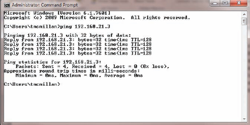
FIGURE 4.9 Echo request and reply
When the destination cannot be reached, an error code will be displayed. The most common of these are as follows:
Destination Unreachable This indicates that the IP datagram could not be forwarded. This also includes an error code (number) that indicates more detail—for example, that there is no routing table entry, or the destination is reachable but did not respond to ARP.
Request Timed Out This indicates that the TTL of the datagram was exceeded. This means you did not even get a response from a router. This can occur if the router is configured to not respond to ICMP, which is not uncommon. This is the situation in Figure 4.10.
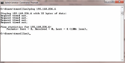
FIGURE 4.10 Request timed out
PING
In Chapter 7, you will learn how to use the ping command to determine the exact nature of a problem.
Another useful command that uses ICMP is traceroute or tracert. On a Cisco router or switch, the command is traceroute. On a Windows computer, the command is tracert.
Whereas ping determines whether you can establish connectivity, traceroute helps you determine exactly where in the network that connectivity broke down. It does this by utilizing the TTL field in the IP datagram (see the section entitled “Describing IP”). It sends a series of ICMP datagrams, and with each successive transmission, it adds one to the TTL. This causes each router in the path to respond. When no response is received from a router, the problem has been located.
In the following example, the output of the traceroute command executed from a router, the command succeeded, and it took four hops to get there. There were responses from three routers and one from the destination device. The output also indicates how long each response took.
router#traceroute 150.1.4.2
Type escape sequence to abort.
Tracing the route to 150.1.4.2
1 150.1.1.2 4 msec 0 msec 4 msec
2 150.1.2.2 4 msec 4 msec 0 msec
3 150.1.3.2 0 msec 0 msec 4 msec
4 150.1.4.2 4 msec * 0 msec
In Figure 4.11, the Windows version, tracert, has been executed to locate the path to a website. You can see that in step 10, it timed out, indicating a problem at that Internet router. It could be that the router is configured not to respond to ICMP.
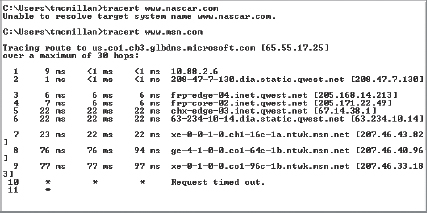
FIGURE 4.11 Tracert
Describing IGMP
The final Internet layer protocol in the TCP/IP suite is Internet Group Management Protocol (IGMP). This protocol is used for multicasting. The protocol operates between routers and hosts that belong to what are called multicast groups. Multicast groups of devices maintain their unicast IP addresses for normal transmissions, but they also share a common multicast address as a group.
Multicast IP addresses are a special range of IP addresses that are dedicated to this purpose and cannot be given to individual devices. When a multicast group is assigned a multicast address, any multicast traffic for the group will be sent to this IP address. The routers on the network will be aware of the devices that are members of the group, as the devices register with the routers. The routers will then send any traffic sent to the multicast address to the individual group members.
Multicast addresses are discussed further in Chapters 7 and 8.
The benefit of multicasting is that it reduces traffic in the network. With unicasting, the server sends a separate message to each separate device. This results in a lot of messages being sent over the network. On the other hand, with multicasting, the server sends one single transmission across the network to the router That reduces the load on the network. The router then sends transmissions to the group members to finish the communication. The two methods are illustrated in Figure 4.12.
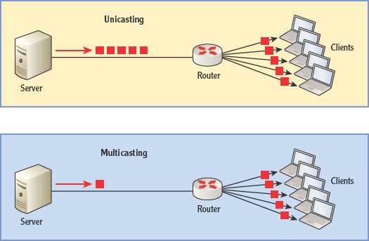
FIGURE 4.12 Multicasting