
Describing Device Functions
Infrastructure devices are those devices that connect sections of the network together, like road systems that connect cities and towns. Some of the devices create connections that operate like limited-access interstate highways connecting cities, while others create connections that are more like secondary highways that connect smaller towns and provide access to the interstate highway at specified entrance ramps. Finally, using the same analogy, some of the devices create connections that might be considered local roads, connecting neighborhoods to the secondary roads.
If you've ever driven in an area where the road system developed over time without a master plan and experienced the headaches that result from this, you can understand why proper network design in the front end is critical. Besides designing for the immediate performance of the network, you need to consider the ability of the network to absorb growth over time without sacrificing performance. Before you can properly design the network and place the devices, you must have an understanding of the functions of the devices, the concepts that guide their operation, and the interrelationships that exist.
One of the best ways to frame the discussion of each device is to map the device to the TCP/IP model. When we do this, it helps to make clear the layers at which the devices operate, and this in turn helps us understand which devices should create interstate highways and which should create secondary roads and so forth from a design perspective.
This section covers the major devices with respect to the following:
- The TCP/IP layers at which they operate
- The roles they can play in the Cisco three-layer model
- The position they occupy in the LAN hierarchy
Understanding Repeaters
Repeaters operate at the Network Access layer of the TCP/IP model, but to say they operate at that layer is really to overstate the intelligence of these devices. The Network Access layer includes both the Network Access layer technology (which in the case of a LAN is Ethernet using MAC addresses) and the physical implementation of that technology. A repeater operates on only the physical part of this layer, so it is sometimes referred to as a physical device.
A repeater simply takes the original signal and amplifies, or boosts, the signal. As you may remember from the discussion about cable length and attenuation in the preceding chapter, after the signal has traversed a certain length of cable, the signal strength is gradually weakened by the resistance in the cable (which is called attenuation). At some point (at the maximum cable length), the signal becomes so degraded that it cannot be understood when it arrives at the destination device. A repeater can be used to connect two lengths of cable that together would exceed the maximum length. It simply amplifies the signal and transmits it.
Repeaters really should be avoided in network design. You should plan the location of the access switches in such a way that no runs of cable over 100 meters are required. You should view repeaters as a solution to a network design problem that you inherited, not one you created. If a bad network design causes a repeater to be included in the network, this device would be considered to be operating on the Access layer of the Cisco three-layer model. This model is discussed in more detail at the end of the chapter.
Understanding Hubs
Hubs operate at the same layer as repeaters and are sometimes referred to as multiport repeaters. They have no intelligence. When a signal is received by a hub on one of its ports, it simply repeats the signal to all other ports. This is illustrated in Figure 10.1. A signal arriving in port 1 is simply sent out all other ports.

FIGURE 10.1 Hub operation
The problem with this operation is that all of the ports are on a shared network. They all exist in one collision domain. You will learn more about collision domains later in this chapter, but for now understand that when signals are regenerated to every port as with a hub, the frequency of collisions is greatly increased. As you learned, collisions lead to retransmissions, which lead to reduced data throughput (that is, a slow network).
Hubs should never be a planned piece in a network design. Over and above the performance problems they introduce, they also create security concerns. If a protocol analyzer or sniffer is connected to a port on the hub or is operating as software on a computer connected to the hub, traffic from all computers connected to the hub can be captured. As explained in the next section, switches segregate devices into separate collision domains (one for each port) and in the process make capturing packets from all devices impossible. If a sniffer is connected to a port on a switch or is running as software on a computer connected to a port on a switch, only the traffic between the sniffer or computer and the switch port can be captured. If a hub is included in the network, it would be considered to be operating on the Access layer of the Cisco three-layer model.
The Cisco three-layer model is discussed at the end of this chapter.
Understanding Bridges
Bridges operate on the Network Access layer of the TCP/IP model, but unlike repeaters and hubs, they go beyond the physical half of the layer and use Ethernet information (MAC addresses) to make forwarding decisions. When a bridge is first started, it acts as a hub does. It sends a frame out every port except for the one on which it arrived. However, in a very short period of time, it learns the MAC address of every device connected to every port. It stores these addresses in a table called the MAC address table. Then, when it receives a frame (these are frames, remember, because we are using information at the Network Access layer), it sends that frame only out the port where the destination MAC address is located, as shown in Figure 10.2. This process is called transparent bridging.
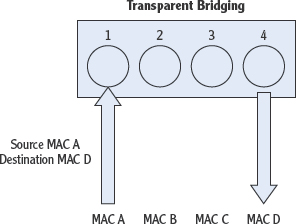
FIGURE 10.2 Bridging operation
The result of this is that each bridge port resides in its own collision domain. The traffic on each bridge port is only traffic destined for that device (or network). That greatly decreases the chance of collisions and in turn lowers the retransmission rate, which increases performance by leaps and bounds.
Bridges have typically been used in the past to connect network segments, rather than devices. So when bridges are used in this manner, each network segment is a collision domain, as shown in Figure 10.3.

FIGURE 10.3 Bridges
Switches provide a port and a collision domain to each device, as shown in Figure 10.4.

FIGURE 10.4 Switches
Bridges are rarely used anymore in networks because the same transparent bridging can be provided by switches, which have many advantages over bridges. These advantages are discussed in the next section. If a bridge is included in the network, it would be considered to be operating on the Access layer of the Cisco three-layer model.
The Cisco three-layer model is discussed at the end of this chapter.
Understanding Switches
Switches also operate on the Network Access layer of the TCP/IP model and use Ethernet information (MAC addresses) to make forwarding decisions. There are all sorts of functions that you can configure on a Cisco switch by connecting to it with a console cable and using the Cisco command-line interface (CLI). But even if you never touch this interface and use the switch as it comes straight out of the box, it will provide the same transparent bridging provided by an Ethernet bridge.
Advantages of Using Switches
The main advantages of a switch over a bridge are as follows:
Software vs. Hardware Bridges perform the bridging function by using soft-ware. Switches, on the other hand, are hardware based. The switching is done using ASIC chips. When hardware is used for this function, the forwarding process is much quicker.
ASICs
Application-specific integrated circuits (ASICs) are those that are dedicated to a specific function, as opposed to a general-purpose integrated circuit. An example is a chip designed solely for a cell phone (you can use it for only that purpose). By using this customized circuitry for the switching function, rather than using the CPU or other more general-purpose circuitry in the switch, performance is greatly enhanced. This is sometimes referred to as switching in the hardware rather than switching in the software.
Port Density Because bridges are designed to connect network segments, they tend to have fewer ports. Switches, on the other hand, normally come in 16-, 24-, and even 52-port models.
Port density simply refers to the number of ports. A device with 24 ports would exhibit more port density than one with 8 ports.
Spanning-Tree Instances Bridges are limited to a single instance of Spanning Tree, while switches can have many. Spanning Tree Protocol (STP) is discussed in Chapter 14, “Configuring Switches.” This protocol is used to prevent switching loops that can occur when switching path redundancy is present in the network.
PATH REDUNDANCY AND LOOPS
If designing path redundancy creates switching loops, why would you include them in the design, anyway? The reason for this is fault tolerance. Just as multiple routing paths between two destinations allows for a backup route if one of the routes becomes unavailable, switching path redundancy provides the same benefit. It is such a beneficial design characteristic that the Spanning Tree Protocol (STP) was designed to prevent loops when switching path redundancy exists. Moreover, you don't even have to enable this; it operates automatically!
So as you can see, there are many reasons that switches are used rather than bridges even though they perform the same function.
Types of Switches
Switches come in two versions: those that operate at the Network Access layer only and those that are called multilayer switches. Multilayer switches operate at both the Network Access and the Internet layers, which means (as you will learn in the next section) they do switching and routing. The rest of this section presents the characteristics of both Network Access layer switches and multilayer switches.
Network Access Layer Switches These switches make forwarding decisions based only on MAC addresses and do not use Internet layer information (IP addresses). They typically act as the connection point to the network for workstations, printers, and other devices on the LAN. A Network Access layer switch is shown in Figure 10.5.

FIGURE 10.5 Network Access layer switch
Because this is the case, these types of switches are said to be operating on the Access layer of the Cisco three-layer model. The functions of switches that operate at this layer are listed here:
The Cisco three-layer model is discussed at the end of this chapter.
- MAC Address Learning The switch identifies the source MAC address whenever a frame enters one of the ports and places this in its MAC address table.
- Forward/Filter Decisions When a frame enters a port, the switch identifies the destination MAC address. If it finds that MAC address in its table, it sends the frame out the port listed for that MAC address only. If it doesn't find the MAC address listed in its table, it will flood the frame out every port except the one on which it arrived.
Port flooding refers to the process of sending a frame out every port except the one on which it arrived.
- Loop Avoidance If switch path redundancy exists in the network, it is the job of the switch to avoid loops. Loops occur when a frame doesn't find its destination and (because of loops that exist in the network for redundancy purposes) continues around the network over and over again. Loops are avoided by the switches communicating with one another using STP to close these loops. You will learn more about STP and its operations in Chapter 14.
SWITCH PATH REDUNDANCY
So what does switch path redundancy look like? The following graphic shows that because of the way switches A, B, and C are connected, there is redundancy between A and C if the direct link between them fails. They can still have a switching path by going through switch B. By building in this fault tolerance, however, a potential switching loop is introduced around switches A, B, and C. STP is used to prevent these loops from causing problems, as you will learn in Chapter 14.

MLS Switches Multilayer switches perform routing and switching, but what is most impressive is the way in which they combine these functions. To appreciate the operation of these devices, consider that when one device is sending data to another device, it is a not a transmission made up of a single packet. It can be made up of hundreds and even thousands of individual packets in the same transmission.
Rather than simply routing each packet (which is what you would expect if this were simply a box containing both a router and a switch), it routes the first packet (routing is a much slower process than switching) and then by maintaining an awareness of that route, it switches all of the other packets in the transmission. This concept has come to be known in the Cisco world as route one and switch many. The result is an impressive increase in speed of the delivery of the entire transmission. Multilayer switches can operate on the Access layer of the Cisco three-layer model. However, in most cases they operate on the Distribution layer, where most routers operate, or on the Core layer of the model, where their speed is one of the main requirements of devices at that layer.
The Cisco three-layer model is discussed at the end of this chapter.
Understanding Routers
Routers operate at the Internet layer of the TCP/IP model and make routing decisions based on IP address information. A router is shown in Figure 10.6.

FIGURE 10.6 Router
The IP address information is stored in routing tables. Routing tables contain routes, or pathways, to networks (called network routes, usually maintained in the form of the network ID) and if configured as such, routes to specific devices (called host routes). They also can contain a type of route called a default route. The router uses the default route to send all traffic for which it has no route in its table. A default route can be thought of as the default gateway for the router because it uses that route much like a host uses its default gateway (that is, a host will send any traffic that is not in its local network to the default gateway). If a router is configured with a default route and you issue the command to show all routes (show ip route), this route is referred to as the gateway of last resort.
Routing tables of the routers can be populated in two ways. When an administrator connects to the router and manually uses commands to program the routes into the routing table, the router will be using static routing. When the router is configured to use a routing protocol, the router will be using dynamic routing. Each of these methods has advantages and disadvantages, which are discussed in the following sections.
Dynamic Routing
When a routing protocol is enabled on a router, it will exchange routing information with other routers that have been enabled with the same routing protocol. Before a router has learned any information from other routers, it will have only routes in its table to networks to which it is directly connected. In Figure 10.7, router R1 has routes in its table only to the 192.168.5.0/24 and 192.168.6.0/24 networks. This is because it is directly connected to only those networks. It does not, however, know about the 192.168.7.0/24 network because it is not directly connected to that network.

FIGURE 10.7 Directly connected routes
Likewise, before any routing information is exchanged between R1 and R2, router R2 will know about only the 192.168.6.0/24 and 192.168.7.0/24 networks, because those are the only networks to which it is directly connected. After the two routers have exchanged their routing tables, both routers will have all three routes in their tables, as shown in Figure 10.8, and only then will a packet from WS 1 destined for WS 10 be routed successfully.
The advantages of dynamic routing are that the remote routes (the routes that are not directly connected) will not have to be entered manually but will be placed in the table automatically as the routers exchange information. The disadvantage is that for this to occur, the routers create traffic on the network called routing update traffic. In some cases, this traffic can be significant and competes with normal data traffic on the network.
Another advantage of dynamic routing is that if multiple paths exist to the same network, as shown in Figure 10.9, the router can use metrics to choose the best route. A metric is a value that is used to determine the best route that can be based on the number of routers on each path (called hops) or on more-sophisticated combinations of information such as hop count and bandwidth. The routers in Figure 10.9 are using hop count (number of routers on the path) as their metric, and so R1 will send any information from WS1 to WS10 through R4 because it's a shorter path in terms of hop count.

FIGURE 10.8 Routing tables updated

FIGURE 10.9 Multiple routes
Moreover, if the best route becomes unavailable (because of link outages, for example), the router can use the other route to still reach the remote network, as shown in Figure 10.10.

FIGURE 10.10 Route fault tolerance
Static Routing
The advantage of using static routing is that there is no routing update traffic created. In some situations where the network is very small and the equipment and connections are very reliable and stable, it may be the best choice. The disadvantages of static routing are as follows:.
- The routes must be entered manually.
- Any changes that occur from a link outage, from a change in design, or from the addition of devices must be made manually.
- The best route choice must be made by the administrator and manually configured.
Understanding Wireless Access Points and Wireless Routers
Wireless access points (APs) can be of two types. Some APs are simply switches that provide logical wireless ports to multiple wireless devices, while others are also routers. In an enterprise network, there is a role for both. Depending on the role of the AP and where it is located in the network, it may not be required for it to be a router, and wireless routers cost more than simple APs. In this section both are discussed.
Wireless APs
An AP that is not a router is acting as a switch. It doesn't look like a switch because it doesn't have physical switch ports that you can see and touch (although some models may include one or two of those). The ports are wireless and they are logical. When a device connects to an AP (which may or may not require authentication), it is said to be associated with the AP.
The AP maintains this information in an association table that is much like the MAC address table in a switch. If a wireless device needs to send traffic that goes through the AP and then on to the wired part of the network, the device will have to have an IP address that is on the same subnet as the network to which the AP is connected. This is the same concept that would apply if a wired device were connected to a switch. This process is shown in Figure 10.11. In this scenario, because AP 20 is operating as a switch and is not a router, laptop 1 will not be able to connect to the router R3 because its IP address is not in the same subnet as the interface on the connection from router R3 to the AP (which is the 192.168.5.0/24 network). The other laptops will not have that problem because their IP addresses are in the same subnet as the router.
SAY THAT AGAIN?
How do we know that router R3 and laptop 1 are not in the same subnet, and what is that 192.168.5.0/24 address all about? Laptops 2 and 3 and the router all have 24-bit subnet masks (255.255.255.0 or /24). That means that if the first three octets of their IP addresses match, they are in the same subnet. Because they all have 192.168.5 in the first three octets, they are all in the same network, which is the 192.168.5.0/24 network. Laptop 1 also has a 24-bit mask, but its first three octets are 192.168.56, so it is not in the same network as laptops 2 and 3 and the router.
When the AP is connected to a router that can provide routing, as shown in Figure 10.11, it is not necessary for the AP to be a router.

FIGURE 10.11 AP as a switch
Wireless Routers
In some situations, it is beneficial or even required for the AP to also be a router. The best example of this is a wireless AP that provides access to the Internet in a home. In this situation, the wireless clients in the home will be using private IP addresses. Because these addresses cannot be used to access the Internet, those addresses must be converted to a public IP address using Network Address Translation. This is a function performed by a router.
Moreover, the AP in this situation will also probably be acting as a DHCP server for the wireless clients. Therefore, it will assign them a private IP address, maintain both the MAC address and the IP address in the association table, and when Internet access is required, it will convert the private IP address to a public IP address. This entire process is shown in Figure 10.12. When laptop 2 sends traffic to the Internet, the AP will convert the IP address 192.168.5.10/24 to the public IP address 202.62.31.9/24.
Regardless of whether the AP is acting as a switch only or as a wireless router, these devices are acting on the Access layer of the Cisco three-layer model.
The Cisco three-layer model is discussed at the end of this chapter.

FIGURE 10.12 Wireless router