
Bonus Appendix B
Installing and Setting Up AutoCAD for Mac
Mastering AutoCAD for Mac
Appendix B accompanies Mastering AutoCAD for Mac, by George Omura and Rick Graham. Learn more about this book at www.sybex.com/go/masteringautocadmac.
This appendix gives you information about installing AutoCAD for Mac on your system and describes the system parameters you should set to configure AutoCAD to meet the needs of your operating environment. Throughout this appendix, the system variable associated with a setting, when available, is included at the end of an option description, enclosed in brackets. System variables are settings that enable you to control AutoCAD’s behavior when you’re using commands and features. You’ll find a detailed description of the AutoCAD for Mac system variables on the AutoCAD for Mac Help website.
Before you begin the installation process, be sure you have at least 1 GB of free disk space. You should also have at least an additional 100 MB of free disk space for AutoCAD temporary files and swap files, plus another 20 MB for the tutorial files you’ll create. AutoCAD will work with Mac OS X Leopard v10.5.8 (or later) or Mac OS X Snow Leopard v10.6.4 (or later).
For serious 3D work, Autodesk recommends at least 4 GB of RAM and 3 GB of available hard disk space (not including the AutoCAD installation).
Single-user systems have a 30-day grace period, so you can install and use AutoCAD without entering your authorization code right away. You can obtain an authorization code by fax, by phone, or over the Internet, as indicated when you first start AutoCAD.
Proceeding with the Installation
AutoCAD for Mac installs like most other Mac applications, but you should know a few things before you start. The following sections provide some information that can be helpful as you begin your installation.
Installing the AutoCAD Software
Installing AutoCAD is simple and straightforward. AutoCAD uses an installation wizard like most other Mac programs. Here are some guidelines to follow during the installation process:
- Before you start, make sure you have enough disk space, and also make sure no other programs are running. You’ll need your AutoCAD serial number, which is provided to you by your reseller or by Autodesk, based on how you purchased your copy of the program. If you’re installing the trial version from the Autodesk website, click Trial on the Register page of the installation wizard.
- Typically, the AutoCAD installation program starts automatically when you insert the AutoCAD for Mac DVD into your computer. In the event that it doesn’t, do the following:
1. Double-click the .dmg file. A file with the .dmg filename extension is a mountable disk image.
2. Double-click the file with the .mpkg filename extension. This is a meta package.
3. A message pops up informing you that it wants to run a program to determine if the software can be installed. Click Continue.
4. The AutoCAD for Mac installer opens. Click Continue to start (Figure B-1).
Figure B-1:The AutoCAD for Mac installer

5. The software license agreement appears. It is recommended that you read and print this out for future reference. Click Continue to go on (Figure B-2).
6. Another box pops up informing you that you must agree to the software license agreement terms. Click Agree to accept the terms.
7. The Register page appears. It is here that you need to enter your serial number and product key (Figure B-3). If you do not have this information, please check with Autodesk or your reseller. Click Continue after you enter the information or click Trial.
Figure B-2:The software license agreement
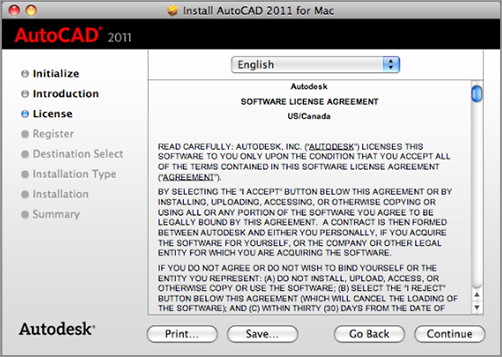
Figure B-3:The Register screen

8. The Installation Type page appears. Within this page, you can customize the install options and locations of files (Figure B-4). Click Install to start the installation. Depending on your Mac settings, you may see a keychain verification window pop up asking you for the admin password to install.
9. During the installation, you will see a progress bar across the Installation page showing you approximately how much time is left for the installation (Figure B-5). The time shown can vary depending on your Mac hardware.
10. Finally, the Summary page appears, informing you that the installation was successful (Figure B-6). Click Close. If for some reason it says it was not successful, then perform an uninstall and reinstall. You may need to redownload the software from Autodesk if all else fails.
Figure B-4:The Installation Type screen

Figure B-5:The Installation screen
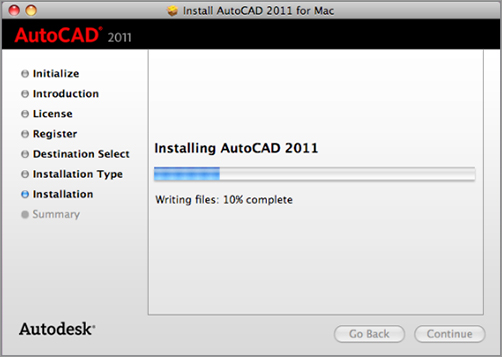
Figure B-6:The Summary screen

In the following sections, you’ll learn how to configure AutoCAD to work the way you want it to. You can configure AutoCAD at any time during an AutoCAD session by using the Application Preferences dialog box.
The tutorials in this book assume that you’re using the default application preferences. As you become more familiar with the workings of AutoCAD, you may want to adjust the way AutoCAD works by using the Application Preferences dialog box. You can also set many of the options in the Application Preferences dialog box through system variables.
Choose Preferences from the right-click menu, press F-, (comma), or type OP↵ at the Command prompt to open the Application Preferences dialog box, which has the tabs and settings described in the following sections.
The General Tab
The General tab (Figure B-7) offers general options such as the zoom direction and frequency of the automatic save. It is divided into five groups: Mouse & Trackpad Customization, Spacebar Customization, File Save Precautions, Zoom Adjustment, and Layout Elements.
Figure B-7:The General tab of the Application Preferences dialog box

Mouse & Trackpad Customization The Enable Quick Secondary Click As Return Key check box offers further options for the behavior of the right-click in AutoCAD. This option causes AutoCAD to respond differently depending on whether you right-click quickly or hold the right mouse button down momentarily. With this option enabled, a rapid right-click issues a ↵, as if you pressed the Enter key. If you hold down the right mouse button, a shortcut menu appears. By default, the check box is unchecked. [Dblclkedit]
The Reverse Zoom Direction check box will do exactly as it says. When it is unchecked (default), to zoom in, you move the middle mouse wheel or swipe up and away from you. With the check box checked, the effect is reversed; moving or swipe down will zoom in. [Zoomwheel]
Spacebar Customization When you use the Pan command in AutoCAD, you can either invoke it by typing ‘PAN↵ or by clicking the Pan button in the status bar. Non-Apple mouse users can also invoke Pan by pressing and holding the middle mouse wheel. With the Enable Spacebar Hold To Pan check box, you have another option. Holding the spacebar down while moving the mouse invokes the Pan command transparently. The spacebar can still be used as the Enter key, or you can repeat the last used command by pressing and releasing the spacebar right away. [Spacepan]
File Save Precautions This section offers control over the Automatic Save feature. You can turn it on or off by using the check box and set the frequency at which files are saved by using the Automatically Save Every X Minutes input box. You can set the location for the Automatic Save files by using the Automatic Save File Location item in the Application tab of the Application Preferences dialog box. You can also set the frequency of automatic saves through the Savetime system variable. [Savefilepath, Savefile]
Zoom Adjustment You can set the speed at which your zoom works on either your mouse wheel or Magic Mouse/Magic Trackpad by moving the slider towards either Slower or Faster. [Zoomfactor]
Layout Elements These options control the display of elements in the Paper Space layouts. See Chapter 8, “Introducing Printing and Layouts,” and Chapter 15, “Laying Out Your Printer Output,” for more information. Most of these options are self-explanatory. When checked (default), the Create Viewports In New Layouts check box automatically creates a single viewport in a layout when it’s first initialized. The Show Page Setup Manager check box opens the Page Setup Manager whenever a layout is first initialized. This is unchecked by default. [Layoutcreateviewport, Showpagesetupfornewlayouts]
The Cursor & Selection Tab
The options in the Cursor & Selection tab of the Application Preferences dialog box (Figure B-8) control the way you select objects in AutoCAD. You can also make adjustments to the Grips feature. There are five groups within this tab: Selection Modes, Selection Tool, Autosnap Marker, Grips, and 3D Modeling Dynamic Input.
Selection Modes The Use Shift Key To Add To Selection check box lets you use the standard method of holding down the Shift key to select multiple objects. When the Shift key isn’t held down, only the single object picked or the group of objects indicated with a window will be selected. Previously selected objects are deselected unless the Shift key is held down during selection. This is on by default. To turn off this feature by using system variables, set Pickadd to 1. [Pickadd]
The Click And Drag To Start Selection check box lets you use the standard method for placing window selections. When this option is selected, you click and hold down the Pick button on the first corner of the window. Then, while holding down the Pick button, drag the other corner of the window into position. When the other corner is in place, you let go of the Pick button to finish the window. In the system variables, set Pickdrag to 1. [Pickdrag]
Figure B-8:The Cursor & Selection tab of the Application Preferences dialog box

Selection Tool The Selection Tool group contains four subgroups:
The Crosshair Lines Length slider controls the size of the crosshair cursor. You can set this to 100 percent to simulate the full-screen crosshair cursor of earlier releases of AutoCAD. [Cursorsize]
The ObjectSnap Aperture Size slider lets you set the size of the object snap aperture pickbox. [Aperture]
The Pickbox Size slider lets you adjust the size of grips. [Gripsize]
The Crosshair Color pop-up will allow you to select the color of the crosshair.
Autosnap Marker Move the Marker Size slider to control the size of the Autosnap marker.
Grips These options control the Grips features:
The Enable Grips check box (checked on by default) controls the display of grips. [Grips]
The Enable Grips With Blocks check box will turn on the display of grips in blocks. This is unchecked by default. Although you can’t edit objects with grips in blocks, you can use grips in blocks as snap points. [Gripblock]
With the Enable Grips Tips check box (on by default), this will control the display of grip tooltips. [Griptips]
The Limit Grip Display to X Selected Objects input box controls the display of grips based on the number of objects selected. If this is set to 1, grips aren’t displayed if more than one object is selected. You can select from a range of 1 to 32,767. The default is 100. [Gripobjlimit]
The Grip Size slider located just below the Limit Grip Display input box lets you adjust the size of grips. [Gripsize]
3D Modeling Dynamic Input When turned on, the Show Z Field For Pointer Input option offers a Z coordinate for input when Dynamic Input mode is used.
The Units & Guides Tab
The options in the Units & Guides tab (Figure B-9) enable you to adjust the way AutoCAD reacts to user input. This tab is divided into six groups: Insertion Scale, Coordinate Display, 3D Objects, Autotrack Settings, Drawing Scale, and Fields.
Figure B-9:The Units & Guides tab of the Application Preferences dialog box

Insertion Scale These controls are used to scale blocks when blocks are assigned a unitless setting for their unit type. Each pop-up menu offers the standard set of unit types that are available. See Chapter 4, “Organizing Objects with Blocks and Groups,” for more information on blocks. [Insunitsdefsource, Insunitsdeftarget]
Coordinate Display The Display Coordinates On Drawing check box will toggle the coordinate display located on the lower-right side of the drawing area.
3D Objects These settings affect the display of 3D objects. The U and V isoline settings let you set the number of isolines on 3D solids and surface meshes. Isolines are the lines you see on a mesh or solid that help you visualize their shape. You see them in wireframe and realistic visual styles. [Surfu, Surfv]
Autotrack Settings These options offer control over the tracking vector used for Polar Tracking and Osnap Tracking:
The Display Polar Tracking Vector check box (on by default) turns the Polar Tracking vector on or off. [Trackpath]
The Display Full-Screen Tracking Vector check box (on by default) lets you control whether the tracking vector appears across the full width of the drawing area or stops at the cursor location or the intersection of two tracking vectors. [Trackpath]
The Display AutoTrack Tooltip check box (on by default) turns the Osnap Tracking tooltip on or off. [Autosnap]
Drawing Scale Click Default Scales List to open the Default Scale. List dialog box. You can add your own custom scales, which appear in the Print dialog box, the Viewport Scales pop-up menu on the status bar, the Properties Inspector palette, and any other place that you can choose a drawing scale.
Fields The Display Background Of Fields check box lets you control the display of the gray background on fields. This background lets you see at a glance which text object in a drawing is a field. The background doesn’t print. [Fielddisplay]
The Look & Feel Tab
The options in the Look & Feel tab (Figure B-10) enable you to adjust the way AutoCAD physically looks. There are five groups within this tab: Interface Theme, Tooltip Appearance, Theme Overrides, Navigation Controls, and Fade Controls.
Figure B-10:The Look & Feel tab of the Application Preferences dialog box

Interface Theme The Themes pop-up menu lets you select between a dark or light color scheme for the AutoCAD interface, including the Tool Sets palette, Layers palette, Properties Inspector palette, and dialog boxes. The following image shows the Dark theme on the left and the light theme on the right.
Tooltip Appearance Tooltips are the text boxes that pop up when you are hovering over a tool. The sliders control the size and transparency of tooltips. The model preview shows what the tooltip will look like when in Model Space. The layout preview shows what it will look like when it is in Paper Space.
Theme Overrides The Modelspace, Paperspace, and Block Editor pop-up menus allow you to change the background color. When you click a pop-up menu, you are presented with a list of theme colors and a Select Color option. When Select Color is selected, it opens up the Color Palette dialog box.

Navigation Controls These options pretty much explain themselves. Each option determines when the ViewCube or UCS icon is displayed. By default, they’re all turned on, so the ViewCube and UCS icons are always displayed.
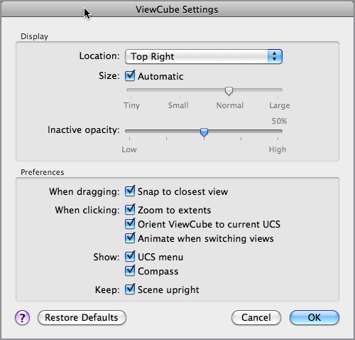
The ViewCube Settings button opens the ViewCube Settings dialog box (Figure B-11). These settings allow you to control the behavior and appearance of the ViewCube.
Figure B-11:The ViewCube Settings dialog box
Fade Controls These two sliders control the fade effect of annotative objects and external references. The Annotative Objects slider controls the display of nonselected objects during in-place reference editing. [Xfadectl] The Xrefs slider sets the overall fade effect. [Xdwgfadectl]
The Application Tab
You use the options on the Application tab (Figure B-12) to tell AutoCAD where to place or find files it needs to operate. It uses a hierarchical list. You first see the general topics in the Files list box. You can expand any item in the list by clicking its disclosure triangle.
Figure B-12:The Application tab of the Application Preferences dialog box
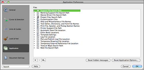
Following are descriptions of each item in the list box. Chances are you won’t have to use most of them, but you may change others occasionally.
When available, the related system variable is shown in brackets at the end of the description.
Support File Search Path AutoCAD relies on external files for many of its functions. Customization, text fonts, linetypes, and hatch patterns are a few examples of features that rely on external files. The Support File Search Path item tells AutoCAD where to look for these files. You can add folder paths to this listing by selecting it and clicking the + button and entering a new path, or you can select it and use the Settings action menu. It’s probably not a good idea to delete any of the existing items under this heading unless you really know what you’re doing.
Working Support File Search Path The Working Support File Search Path item contains a read-only list of the support-file search paths for the current session, including any internally defined locations.
Device Driver File Search Path The Device Driver File Search Path item locates the device drivers for AutoCAD. Device drivers are applications that enable AutoCAD to communicate directly with output and input devices. In most cases, you don’t have to do anything with this setting.
Project Files Search Path Eventually, a consultant or other AutoCAD user will provide you with files that rely on Xrefs or raster images. Often, such files expect the Xref or raster image to be in a particular folder. When they are moved to another location with a different folder system, Xref-dependent files won’t be able to find their Xrefs. The Project Files Search Path item enables you to specify a folder where Xrefs or other dependent files are stored. If AutoCAD is unable to find an Xref or other file, it will look in the folder you specify in this listing.
To specify this folder, highlight Project Files Search Path and then click the + button. AutoCAD suggests Project1 as the folder name. You can change the name if you prefer. The current project file search path is stored in a system variable called Projectname. [Projectname]
Customization Files If you’re customizing AutoCAD with your own menu files and icons, you can use this setting to locate your files. This option makes it convenient to keep your customization files in a place that is separate from the standard AutoCAD files. You can specify a location for the main customization files like your CUI files, custom icons, and the PGP file that defines your command aliases.
Help And Miscellaneous File Names This item lets you set the location of a variety of support files, including help and configuration files.
Text Editor, Dictionary, And Font File Names Use this item to set the location of the alternate font and font-mapping files. Chapter 9, “Adding Text to Drawings,” describes these tools in more detail. [Fontalt]
Print File, Spooler, And Prolog Section Names You can specify a print filename other than the default that is supplied by AutoCAD whenever you print to a file. The Print Spooler Executable item lets you specify an application intended to read and print to a file. The PostScript Prolog Section Name option is intended for PostScript export. It lets you specify the Prolog section from the acad.psf file that you want AutoCAD to include with exported Encapsulated PostScript files. [Psprolog]
Printer Support File Path Several support files are associated with the AutoCAD printing system. This item enables you to indicate where you want AutoCAD to look for these files.
Automatic Save File Location You can indicate the location for AutoCAD’s Automatic Save file by using this item. [Savefilepath]
Color Book Locations This item lets you specify the locations for the color books used by the Color command and Color property for objects.
Template Settings When you create a new drawing, AutoCAD looks at this setting for the location of template files. You can modify this setting, but chances are you won’t need to.
Log File Location With this item, you can indicate where log files are to be placed. [Logfilepath]
Plot And Publish Log File Location With this item, you can indicate where print log files are to be placed. [Logfilepath]
Temporary Drawing File Location AutoCAD creates temporary files to store portions of your drawings as you work on them. You usually don’t have to think about these temporary files unless they start crowding your hard disk or unless you’re working on a particularly large file on a system with little memory. This item lets you set the location for temporary files. If you have a hard disk that has lots of room and is very fast, you may want to change this setting to a location on that drive to improve performance. [Tempprefix, read-only]
Temporary External Reference File Location The Temporary External Reference File Location item lets you specify the folder where AutoCAD stores this copy of an Xref. [Xloadpath]
Texture Maps Search Path This item specifies the location for AutoCAD Render texture maps. In most cases, you won’t have to change this setting. You can, however, add a folder name to this item for your own texture maps as you acquire or create them.
Web File Search Path Although you may think this is for Internet files, it’s really for photometric web files that are used to control the way weblights behave in 3D models. These files have an .ies filename extension.
While in AutoCAD, you may want to quickly find the location of a resource file such as a log file or the Automatic Save file. You can do so by using the system variable associated with the resource. For example, to find the location of the log file path quickly, enter LOGFILEPATH↵ at the Command prompt. For the Automatic Save file, enter SAVEFILEPATH↵.
You will notice that there are two additional buttons at the bottom of the Application tab of the Application Preferences dialog box.
Reset Hidden Messages This will reset any settings that you have previously set as Do Not Show This Again.
Reset Application Options This will reset your entire AutoCAD for Mac system back to the original “out of the box” settings. This is a potentially dangerous option because it will wipe any custom settings such as preferences and Customizable User Interface (CUI) settings. Use this only as a last-resort measure.
The Document Settings Tab
The Document Settings tab (Figure B-13) contains 2D and 3D display resolution settings. There are two groups: 2D Display Resolution and 3D Display Resolution.
Figure B-13:The Document Settings tab of the Application Preferences dialog box

2D Display Resolution The Polyline Curve Segments slider controls the amount of segments in a splined polyline. The higher the value, the more memory and disk space will be taken. [splinesegs]
The Arc & Circle Smoothness slider controls the amount of segments that occur in an arc or circle. [viewres]
3D Display Resolution The Contour Lines Per Surface slider controls the number of isolines in a 3D object. [isolines]
The Smoothness For 3D Printing Rendering slider controls the amount of smoothness on rendered 3D objects. It also controls smoothness when the Hidden viewport style is selected. [facetres]
If for some reason the Grips feature isn’t available, follow these steps to turn it on:
1. In the Application Preferences dialog box, choose the Cursor & Selection tab.
2. In the Grips group, click the Enable Grips check box.
3. Click OK, and you’re ready to proceed.
The Cursor & Selection tab of the Application Preferences dialog box also lets you specify whether grips appear on objects that compose a block (see Chapter 4 for more on blocks). You can also set these options by using the system variables.
You can also turn the Grips feature on and off by entering ‘GRIPS↵. At the Enter new value for GRIPS <0>: prompt, enter 1 or 2 to turn grips on or 0 to turn grips off. The 2 value turns on grips and displays additional midpoint grips on polyline line segments. Grips is a system variable that is stored in the AutoCAD configuration file.
Setting Up the Tracking Vector Feature
If AutoCAD doesn’t display a tracking vector as described in the early chapters of this book, or if the tracking vector doesn’t behave as described, chances are this feature has been turned off or altered. Take the following steps to configure the tracking vector so it behaves as described in this book:
1. Open the Application Preferences dialog box.
2. Click the Units & Guides tab.
3. Click all three options in the Autotrack Settings group.
4. Click OK to exit the dialog box.