
Chapter 21
Rendering 3D Drawings
In this chapter, you’ll learn how to use rendering tools in AutoCAD to produce rendered still images of your 3D models. With these tools, you can add materials and control lighting. You also have control over the reflectance and transparency of objects.
In this chapter, you’ll learn to do the following:
- Simulate the sun
- Create effects using materials and lights
- Control your render quality
- Print your renderings
Before we get into the main tutorial in this chapter, let’s first take a peek at what’s possible with AutoCAD’s rendering tools. This first exercise will give you a chance to learn how you can quickly see a rendered view of a 3D model and how you can easily add materials to objects.
The first file you’ll work with in this section is simply a collection of primitive shapes in a random arrangement. First, you’ll use the Render command to view the file without any materials, and then you’ll add a few materials to get familiar with the Material Browser and see how it can be used to create a more lifelike rendering. Start by opening a sample file and render it as is:
1. First, turn on the Selection Cycling system variable by entering SELECTIONCYCLING↵ 2↵. You’ll need it in some of the later exercises.
2. Make sure Modeling is selected in the Tool Sets palette.
3. Next, open the Material Browser by choosing View Render Materials Browser (Figure 21-1).
4. Open the Rendering_example_raw.dwg file.
5. Click the Render tool in the lower part of the Tool Sets palette (Figure 21-2).
6. The Render window opens and takes a moment to produce the rendered view (Figure 21-3).
Figure 21-1:The Material Browser

Figure 21-2:The Render icon in the Tool Sets palette
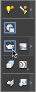
Figure 21-3:The Render window with the rendered view

All of the objects in the view are rendered using the default Global material.
Now try adding a material to the sphere:
1. Take a look at the Material Browser in Figure 21-4. Click the disclosure triangle to the left of the Autodesk Library option. This opens a list of material categories.
Figure 21-4:The Material Browser with the expanded Autodesk Library option
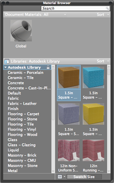
2. Scroll down the categories list and select Metal. A set of materials is displayed in the panel to the right of the list.
3. In the list on the right, click Brass – Polished. Brass – Polished appears at the top of the Material Browser.
4. Click the sphere in the drawing and then click the Brass – Polished icon. You’ll notice that the sphere changes color to indicate its new material.
5. Click the Render tool again to see the result.
You now see that the sphere appears to be made of polished brass in the rendered view. In this exercise, you applied a material by clicking and dragging it to an object.
Now add a few more materials using a slightly different method:
1. Click the cylinder to the far left of the drawing area to select it.
2. In the Material Browser, scroll down the list of materials on the right-side panel to locate Chrome – Polished.
3. Click Chrome – Polished to apply it to the cylinder.
4. Next, click the foreground of the 3D model to select the rectangle that defines the “ground,” as shown in Figure 21-5.
Figure 21-5:Click the foreground surface to select it.

5. Back in the Material Browser, scroll the list on the left-hand side to locate and select Fabric.
6. In the panel to the right, locate and select Plaid 1. This applies the Plaid 1 material to the “ground.”
7. Click the Render tool again.
8. Once you’ve had a chance to look at the rendering, close the Rendering_example_raw.dwg file without saving it.
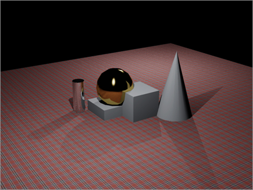
After rendering the view in step 7, you could see the Plaid 1 material of the foreground reflected in the brass sphere and chrome cylinder (Figure 21-6). The added materials give the rendered view a more realistic appearance.
Figure 21-6:The rendered view with additional materials
This brief introduction to materials and rendering shows you some of the potential of these tools. In the rest of the chapter, you’ll get an in-depth view of the many ways you can control the appearance of rendered views from your 3D models.
Creating a Quick-Study Rendering
Throughout the rest of this chapter, you’ll work with a 3D model that was created using AutoCAD’s 3D modeling tools. The model is of two buildings on a street corner. You’ll start by using the default rendering settings to get a quick view of what you have to start with:
1. Open the facade.dwg file.
2. Click the Render tool near the bottom of the Tool Sets palette.
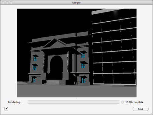
3. The Render window appears, and you see the rendering generated in the Render window display (Figure 21-7).
Figure 21-7:The Render window with your first rendered view of the building

AutoCAD allows you to create several types of light sources. If you don’t add a light source, AutoCAD uses two default lighting sources that have no particular direction or characteristic. The rendering you just did uses the default lighting to show your model.
You can add a point light that behaves like a lightbulb, a spotlight, or a directed light that behaves like a distant light source such as the sun. AutoCAD also offers a sunlight option that can be set for the time of the year and the hour of the day. This sunlight option is especially important for shadow studies in architectural models.
Setting Up the Sun
Let’s add the sun to the model to give a better sense of the building’s form and relationship to its site. Start by making sure the sun is set for your location:
1. Click the Sun Status button in the expanded Status Bar palette (Figure 21-8).
Figure 21-8:The Sun Status button in the expanded Status Bar palette

You may see a message box warning you that the default lighting must be turned off when other lights are used. Click Turn Off The Default Lighting.
2. Make sure nothing is selected in the drawing and then click All near the top of the Properties Inspector palette.

3. Scroll down the list to the Sun and Sky category. Notice that you have quite a few options that let you control the sun’s intensity and shadow effects (Figure 21-9).
Figure 21-9:The Sun properties in the Properties Inspector palette

4. Click the Render tool in the Tool Sets palette. The Render window appears and begins to create a new rendering with the sunlight option turned on.
Now that you’ve added the sun, you can see the shadows that the sunlight casts. You can turn off the shadows for the sun if you prefer, but they’re on by default.
Using Distant Lights
As you begin to use the lights in AutoCAD, you’ll come across the distant light. A distant light is like a cross between a point light and a spotlight and is similar to the sun in AutoCAD. The sun is a point source of light, but it’s so far away that its rays are essentially parallel. A distant light behaves in a similar way. It has a point location, yet its light rays are parallel.
When you click the distant-light tool in the expanded Lights tool group in the Tool Sets palette, you are asked for a light location and direction. You can use object snaps to accurately place the location and direction of a distant light to control things like shadows and light reflection. Note that when you turn on the Lightingunits system variable described later in this chapter (in the section entitled “Using the Sun and Sky Simulation”), you are prompted to disable distant lights.
Creating Effects Using Materials and Lights
Up to now, we’ve talked about only two light sources: a distant light and the sun. Two other light sources are available to help simulate light: point-light sources and spotlights. The following sections will show you some examples of how to use these types of light sources, along with some imagination, to perform any number of visual tricks.
The office building on the right half of the rendering is still a bit cold looking. It’s missing a sense of activity. You may notice that when you look at glass office buildings, you can frequently see the ceiling lights from the exterior of the building—provided the glass isn’t too dark. In a subtle way, those lights lend a sense of life to a building.
Adding Glass to the Windows
The glass parts of the model are rendered in the color of their layer. You can add a glass material to make them appear more like glass in a building.
Earlier in this chapter, you added metal and fabric materials to a sample model. The process is the same for glass:
1. If the Material Browser isn’t open, open it now by choosing View Render Materials Browser on the menu bar.
2. If the Autodesk Library is blank, click the disclosure triangle to the left to expand the list.
3. Scroll down the list and select Glass glazing. The list to the right shows several sample glass types.
4. Scroll down the list to the right and click Light Bronze Reflective. The sample of Light Bronze Reflective appears at the top of the Material Browser.
5. In the drawing window, select the blue box representing the glass (Figure 21-10).
Figure 21-10:Selecting the object representing glass in the model
6. Click the Light Bronze Reflective sample at the top of the Material Browser. This applies the material to the selected object.
7. Click the Render tool in the Tool Sets palette. The building to the right now appears to be made of glass (Figure 21-11).
Figure 21-11:The building rendered with the sun turned on and a glass material added
Adding a Self-Illuminated Material
With the Light Bronze Reflective material assigned to the glass, you begin to see a little of the interior. To help improve the image, you’ll add some ceiling lights to the office building. I’ve already supplied the lights in the form of square 3D Faces arrayed just at the ceiling level of each floor, as shown in Figure 21-12. In this section, you’ll learn how to make the ceiling lights appear illuminated.
Figure 21-12:The 3D Face squares representing ceiling light fixtures
Follow these steps to assign a reflective white material to the ceiling fixtures:
1. In the Material Browser, select Glass from the Autodesk Library list.
2. In the icon list to the right, scroll down until you see Light Bulb – On and click it.
3. In the Layers palette, right-click the Clglite layer and select Isolate Selected Layer.
4. Select all of the remaining cyan rectangles in the view.
5. Click the Light Bulb – On thumbnail in the top portion of the Material Browser to assign that material to the cyan rectangles.
6. In the Layers palette, turn all of the layers back on.
7. Render your view. The lights appear in the ceiling of each of the floors (Figure 21-13).
In the previous exercise, you added a self-illuminated material that, when assigned to an object, appears to glow. You then added this material to the ceiling lights in the model. This self-illuminated material doesn’t actually produce light in the model, however. To do that, you’ll have to add light objects such as a distant lights or spotlights.
Figure 21-13:The lights appear in the ceilings of the building to the right.

Using Procedural Maps
Procedural maps are texture maps that are derived mathematically rather than from a bitmap image. The advantage of a procedural map is that it gives a more natural representation of a material. For example, if you cut a notch out of a box that uses a wood procedural map, the notch appears correctly with the appropriate wood grain. Do the same for a box that uses a bitmap texture map and the grain doesn’t appear correctly. With a bitmap texture map, the same image is placed on all four sides of the box, so cuts don’t show the grain properly.

AutoCAD offers several types of procedural maps. You can select them from the Material Browser for materials such as ceramic, concrete, masonry, plastic, stone, and wood.
Using the Sun and Sky Simulation
You can set up AutoCAD to simulate realistic lighting effects in exterior views. Earlier in this chapter, you added a distant light to approximate the light bouncing off the ground. AutoCAD’s Sun and Sky Simulation feature offers a more accurate rendition of reflected light that takes into account the light bouncing off neighboring buildings and surfaces. To see how this feature works, try the following exercise:
1. At the Command prompt, enter Lightingunits↵.
2. At the Enter new value for LIGHTINGUNITS <0>: prompt, enter 2.
If you have a drawing that uses distant lights, you may see a warning message asking if you want to disable distant lights. Leave them enabled by selecting Allow Distant Lights.
By changing the Lightingunits setting, you turn on the Photometric Lighting feature in AutoCAD. The Photometric Lighting feature gives you finer control over the intensity of the lights you add to your model. The Lightingunits system variable can be set to 0 (generic units), 1 (international units), or 2 (American units). When you are in a perspective view and Lightingunits is set to 1 or 2, you can turn on the Sun and Sky Simulation feature.
This next exercise demonstrates how the Sun and Sky Simulation feature works:
1. Click the Sky Status pop-up menu in the Status Bar palette and select the Sky Background And Illumination option.

2. The background of your main view changes.
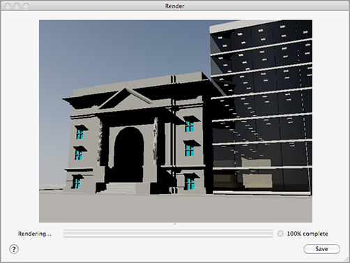
3. Click the Render tool. After a minute or two, you get a finished rendering. Your model renders using the current Sun settings. The shadows on the center building are more realistic and show more detail of the building (Figure 21-14).
Figure 21-14:The rendering with the Sky Background And Illumination feature turned on
You can further refine your image by adjusting the brightness of the sun and sky. Here’s how:
1. Press the Esc key to make sure nothing is selected.
2. Click the All option near the top of the Properties Inspector palette.
3. Scroll down to the Sun & Sky category (see Figure 21-15).
Figure 21-15:Click the All option and adjust the Sun & Sky category.
4. Change the Intensity Factor setting to 2. This has the effect of brightening the sun.
5. Render the view again.
This time, the rendering is brighter and has more contrast.
Simulating a Night Scene with Spotlights
Spotlights are lights that can be directed and focused on a specific area. They’re frequently used to provide emphasis and are usually used for interior views or product presentations. In this exercise, you’ll set up a night view of the Facade model by using spotlights to illuminate the facade.
You’ll start by setting up a view to help place the spotlights. You’ll save this view because you’ll be going back to it several times:
1. Select SE Isometric from the 3D Views menu on the viewport controls.
2. Right-click the ViewCube and select Parallel (Figure 21-16).
3. Adjust your view so it looks similar to Figure 21-17.
4. Save this view by typing View↵ S↵ SE Isometric Wireframe↵.
Figure 21-16:Select Parallel from the ViewCube’s shortcut menu.

Figure 21-17:Set up your view to look similar to this, and then add the spotlight.
Now you’re ready to add the lights:
1. Click the Spotlight tool from the lower part of the Tool Sets palette (Figure 21-18), or enter Spotlight↵ at the Command prompt.
Figure 21-18:Click the Spotlight tool from the Tool Sets palette.

2. At the Specify source location <0,0,0>: prompt, click the point shown in Figure 21-17. Don’t use osnaps because you don’t want the light to be placed accidentally below the ground plane. You don’t have to be exact, but the idea is to place the spotlight in front of the windows on the right side of the entrance to the building.
3. At the Specify target location <0,0,-10>: prompt, use the Midpoint osnap and select the bottom of the windowsill of the upper window, as shown in Figure 21-17. You see the prompt
Enter an option to change
[Name/Intensity/Status/Hotspot/Falloff/shadoW/Attenuation/Color/eXit] <eXit>:
4. Press ↵ to accept the default settings. You can always change the optional settings for the light through the Properties Inspector palette.
5. Copy the spotlight you just created to the location shown in Figure 21-19. You can use the spotlight target to copy from the midpoint of one window sill to the other.
Figure 21-19:Copy the spotlight to this location.

6. You’re trying to produce a nighttime rendering, so turn off the sun by clicking the Sun Status button in the expanded Status Bar palette.
7. Return to the original view by choosing Model Views Temp from the 3D Views menu in the viewport controls.
8. Turn off the Lightingunits system variable by typing LIGHTINGUNITS↵ 0↵.
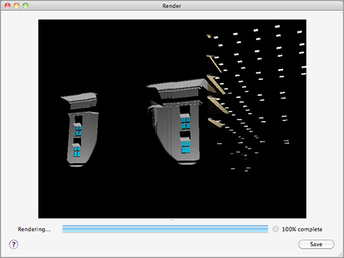
9. Click the Render tool in the Tool Sets palette to see the results of your spotlight addition. Your rendering will look similar to Figure 21-20.
Figure 21-20:The rendered view of the model with the spotlights
Adding a Point Light
A few things still need to be added to improve this rendering. You can adjust the spotlight so it casts light over a wider area. You can also add a light in the entrance so it isn’t quite so dark. The next section will show you how to make adjustments to your spotlight. First, you’ll add a point light to obtain a different lighting effect:
1. Return to the view you used to add the spotlights by choosing SE Isometric Wireframe from the 3D Views menu in the viewport controls.
2. Click the Point tool from the lower part of the Tool Sets palette (Figure 21-21) or enter Pointlight↵.
Figure 21-21:Click the Point tool from the Tool Sets palette.

3. At the Specify source location <0,0,0>: prompt, ![]() -right-click and select Center from the Object Snap shortcut menu. Then select the arch over the entrance, as shown in Figure 21-22, to place the point light.
-right-click and select Center from the Object Snap shortcut menu. Then select the arch over the entrance, as shown in Figure 21-22, to place the point light.
Figure 21-22:Select the center of the arch.
4. At the prompt
Enter an option to change [Name/Intensity/Status/shadoW/
Attenuation/Color/eXit] <eXit>:
press ↵ to accept the default settings for the point light.
5. The point light appears as a spherical glyph in the archway of the building.
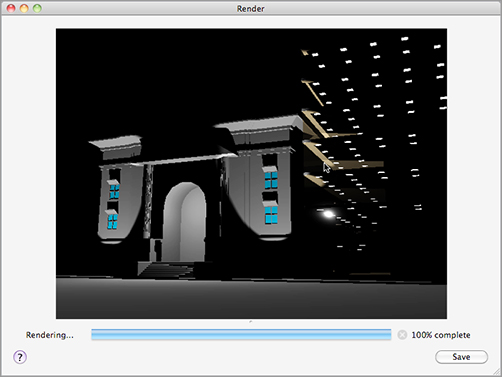
6. Click the Render tool in the Tool Sets palette. Your rendering will look similar to Figure 21-23.
Figure 21-23:The rendered view of the model with the spotlights modified and the point light added
Editing Lights
You’ve added the point light. Before you see the results in a rendering, you’ll also change the spread of the spotlights. In this exercise, you’ll edit the properties of the spotlight. Not all lights have the same properties, but the basic process for editing all lights is the same:
1. ![]() -click the two spotlights to select them.
-click the two spotlights to select them.
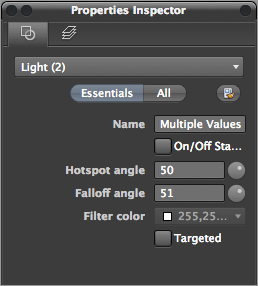
2. Click Essentials in the Properties Inspector palette. You’ll see that there are a number of settings available, including Intensity Factor. You can adjust these settings to control the lights (Figure 21-24).
Figure 21-24:Light adjustment options in the Properties Inspector palette
Notice that there is one red and one yellow light cone for each spotlight. The cones also have an arrowhead at each of four locations around the widest part of the cone. These are the hotspot and falloff cones. They help you visualize the size of the hotspot and falloff of the light from each spotlight. Next, adjust the falloff of both spotlights to soften their effect on the view:
1. Click the arrowhead at the spotlight cone to the right (Figure 21-25). A text box appears that reflects the angle of the falloff for the spotlight.
2. Type 90↵. The cone changes shape to become wider.
3. Repeat steps 1 and 2 for the spotlight to the left.
Figure 21-25:Click the arrowhead on the spotlight cone shown here.

4. Render the view. Now the spotlights have a softer effect (Figure 21-26).
Figure 21-26:The model rendered with the falloff adjusted to 90 degrees

In step 2, you saw a list of options for the spotlight. Many of these options are available when you first insert the light; they appear as command-line options. Often, it’s easier to place the light first and then play with the settings.
Figure 21-27:The hotspot and falloff of a spotlight at the top produce the lighting shown at the bottom.

In this example, you adjusted the spotlight’s falloff. By increasing the falloff angle, you broadened the spread of the light cast by the spotlight and also made the transition from light to dark appear smoother, as shown in Figure 21-27. The hotspot can also be adjusted to a narrow beam or a wide swath.
Many other light properties are available to you in the Properties Inspector palette. Table 21-1 describes them.
Table 21-1: Some of the properties available for lights
| Property | Description |
| General | |
| Name | Shows the name of the light |
| Type | Sets the type of light |
| On/Off Status | Shows whether light is on or off |
| Hotspot Angle | Sets the spotlight hotspot angle |
| Falloff Angle | Sets the spotlight falloff angle |
| Intensity Factor | Sets the light intensity |
| Filter Color | Sets the secondary light color simulating a color filter over a lamp |
| Plot Glyph | Allows the light glyph to be plotted |
| Glyph Display | Controls the display of the light glyph |
| Attenuation | |
| Type | Type of attenuation: Inverse Linear, Inverse Square, or None |
| Use Limits | Lets you turn on attenuation limits |
| Start Limit Offset | If Use Limits is on, sets the distance to the beginning of attenuation |
| End Limit Offset | If Use Limits is on, sets the distance to the end of attenuation |
| Rendered Shadow Details | |
| Type | Lets you select between sharp and soft shadow edges |
| Map Size | When shadow maps are used, lets you determine the size of the shadow map in pixels |
| Softness | When shadow maps are used, determines the softness of shadows |
Improving the Smoothness of Circles and Arcs
Here is an issue that readers are constantly asking me about. You may notice that at times, when you’re using the Render, Hide, or Shade tool, the edge of solids or region arcs appears segmented rather than curved. This may be fine for producing layouts or backgrounds for hand-rendered drawings, but for final prints, you want arcs and circles to appear as smooth curves. You can adjust the accuracy of arcs in your hidden, rendered, or shaded views through a setting in the Application Preferences dialog box.
You can modify the Smoothness For 3D Printing/Rendering setting in the Document Settings tab of the Application Preferences dialog box to improve the smoothness of arcs. Its default value is 0.5, but you can increase it to as high as 10 to smooth out faceted curves. In the facade.dwg model, you can set Smoothness For 3D Printing/Rendering to 1.5 to render the archway in the entry as a smooth arc instead of a series of flat segments. You can also adjust this setting by using the Facetres system variable.
Once you’ve rendered your model, you may find that you need to make some changes to the rendered image. You can always export the image to another program like Photoshop, to “dress up” the image and adjust lighting and contrast. There are a few things you can do within AutoCAD as well.
One feature you can use to improve the overall sharpness of your rendering is the Renderquality setting. So far, the renderings of the building have been a bit jagged. You can create a smoother image by typing RENDERQUALITY↵ 5↵. This sets the Renderquality setting to its maximum value of 5. You can use a range from –3 to 5, with -3 being the lowest quality. With Renderquality set to 5, you will see smoother edges and more detail in your renderings.
If your rendered image is too dark or you want to bump up the contrast, the Properties Inspector palette offers the Brightness, Contrast, and Midtone settings under the Render category. You can find these settings at the bottom of the Properties Inspector palette when you click the All button. Make sure you do not have anything selected in your drawing before you click All.
When you’ve decided that your rendering is perfect, you can print a copy directly from AutoCAD. Through a layout view, you can also put together presentations that include 2D floor plans and elevations with your rendering on a single sheet. Alternatively, you can have several renderings on one sheet.
Try the following to set up a layout view to render the 3D model in both a rendered view and a hidden-line view:
1. Click the Show Drawings And Layouts button in the Status Bar palette and then choose Layout1.
2. Click the viewport border to expose its grips, and then use a grip to make the viewport smaller so it’s about half the height of the Paper Space layout. Keep the height-to-width proportions of the viewport as close to the original as possible.
3. Double-click inside the viewport and then select Model Views Temp from the 3D Views menu on the viewport controls.
4. Make sure the Sun Status button in the expanded Status Bar palette is on.
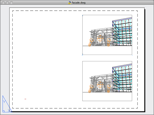
5. Double-click outside the viewport, and then copy the viewport so you have an identical viewport near the original (Figure 21-28).
Figure 21-28:The preview with duplicate views
Now you’re ready to set up the viewport to render the views in specific ways. For example, you can set one viewport to render as a fully rendered view while rendering another viewport as a hidden-line view:
1. Click the border of the top viewport, right-click, and choose Shade Plot Rendered.
2. Click the border of the lower viewport, right-click, and choose Shade Plot Hidden.
3. Choose File Print on the menu bar.
4. Choose a printer name for the Printer pop-up menu, and then click Preview. After a moment, you see a preview of your plot showing a fully rendered view in the top viewport and a hidden-line view in the lower viewport (Figure 21-29).
You can add viewports to include floor plans and elevations if needed. Another option is to add isometric views with labels that point out drawing features.
You also have control over the quality of the rendered viewport. Choose File Page Setup Manager on the menu bar. The Page Setup Manager dialog box opens. Click the Gear icon just below the Current Layout list, and choose Edit to open the Page Setup dialog box. Next, click the Advanced button. You can use the 3D Viewports group to select from a pair of viewport-quality settings (Figure 21-30).
Figure 21-29:The final comparison rendering

Figure 21-30:Select a quality setting from the Quality pop-up menu.

You can choose from Draft, Preview, Normal, Presentation, Maximum, and Custom. Custom enables the DPI setting, allowing you to control the resolution of your output. These options are described in detail in Chapter 8, “Introducing Printing and Layouts,” so I won’t go into detail here. Just remember that the options are available to help you get the most from your rendered printer output.
Getting a Sketch Presentation with Visual Styles
One of the most interesting issues I’ve encountered while creating 3D presentations of buildings is that, quite often, architects do not want a realistic rendering of their designs. The reason is that a realistic rendering gives the impression that the design is already “set in stone” or has progressed to a more advanced level than it actually has.
So although this chapter has focused on getting a realistic rendering of your model, frequently you’ll want to show your model in a less realistic view. This is especially true in the early stages when you don’t want to give the impression that you’ve created a finished design. There are several visual styles you can use to this end.
You can print visual styles from either the model or named layout view. If you choose a layout view to print a visual style, select the viewport border, and select As Displayed from the Shade Plot drop-down list. Then select the visual style you want to use for your print from the Viewport Visual Styles drop-down list inside the viewport.
Simulate the sun. One of the most practical uses of AutoCAD’s rendering feature is to simulate the sun’s location and resulting shadows. You can generate shadow studies for any time of the year in any location on the earth.
Master It How do you get to the sun properties?
Create effects using materials and lights. You can use materials and lights together to control the appearance of your model.
Master It Name the part of the example model in this chapter that was used to show how a material can appear to glow.
Control your render quality. AutoCAD offers a few features to give you some control over the quality of your rendering. The default rendering settings allow you to view your rendering at a level good enough to gauge how it will look.
Master It Name the two features discussed in this chapter that allow you to control the quality of your renderings.
Print your renderings. You can save your rendered views as bitmap files using the Render window. If you prefer, you can also have AutoCAD include a rendering in a layout. You can include different renderings of the same file in a single layout.
Master It Give a general description of the process for setting up a rendered viewport in a layout.