Ductwork, like pipework, is a system family through which Revit MEP can calculate air flow rates and pressure drops on any correctly defined system. It also provides the graphics for the traditional "drawn" documentation and the variety of ways this can be represented on a drawing sheet at different stages of a project, regardless of whether this is "single line" at concept design or fully coordinated "double line" for construction issue.
There are three main types of duct: rectangular, round, and — new to Revit MEP 2011 — oval. These three types are the basis for your designs. They connect to air terminals and a variety of mechanical equipment. They also host duct fittings and accessories. By using the fittings and accessories available with the standard installation, the user can create supply, return, and exhaust systems with very little additional thought.
During your implementation, however, you should also consider the benefits of creating additional duct types that suit the way you work and your company standards.
In this chapter, you will learn to
Distinguish between hosted and nonhosted components
Use the different duct routing options
Adjust duct fittings
Air distribution components come in many different shapes and sizes. Depending on the design, they can be mounted in a variety of ways, including the following:
Diffusers in a ceiling
Duct-mounted sidewall diffusers
Wall mounting
Suspended
In each of these instances, the designer must decide whether to have hosted fittings (and if so, which type of hosting) or whether to not host at all. There are different — and similar — ways of placing these objects, and some may be conflicting.
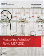
An example of this is an installation where there are diffusers hosted in the ceiling as well as areas where the architect's design is for suspended fittings (see Figure 10.1). In this project, assume there is an external architect, and the architectural model is being linked. This means straightaway that you cannot use ceiling-hosted air terminals. Although you can see the linked ceiling, Revit only recognizes it as a face, and because of this, the air terminals will need to be created as face-hosted families.
The most important point here is that once you commit to one type of family (hosted, nonhosted, wall, and so on), you can exchange for example, Air Terminals, with similarly created Air Terminals, not just those that are of the same category (see Figure 10.2).
The next problem is that the air terminals that are suspended are in fact the same type as those mounted within the ceiling tiles. The engineer wants to be able to schedule and filter them as one. How do you manage this?
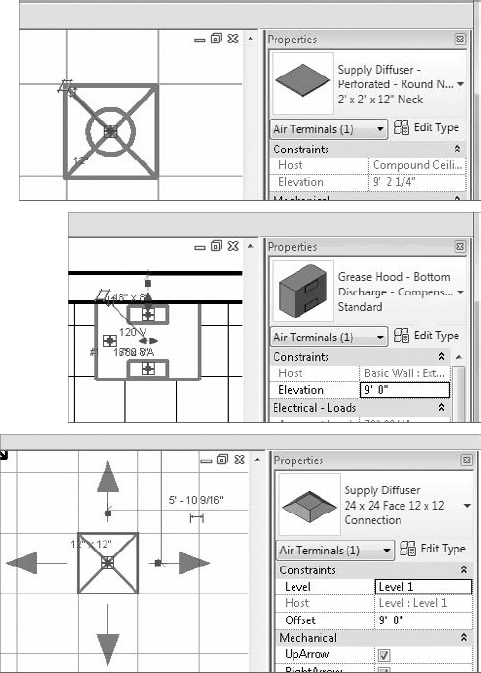
New to Revit MEP 2011 is the ability to copy/monitor air terminals (as well as lighting fixtures, mechanical equipment, and plumbing fixtures). This means the services engineers can monitor the locations of air terminals that the architect has placed because the architect is responsible for placing these objects. As with the other items that can be copy/monitored, the services designer can choose to copy the original family type from the linked file or "map" it to one of their own choosing. In Figure 10.3, you can see, however, that once the air terminals have been copied/monitored, it does not matter what type of host association there is because this ceiling-hosted family has no host but is in the correct location specified by the architect.

Mechanical equipment is the componentry that makes up the majority of large to medium-size plant objects for the mechanical designer. From air conditioners (ACs) and air-handling units (AHUs) to air curtains and heat pumps, these all provide the geometry and parameters associated with HVAC design. As with all components, choosing the hosting type is important. A level-hosted object cannot be exchanged for a face-hosted or ceiling-hosted one.
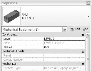
The heart of the mechanical air system, air conditioning/handling units can start life as generic "boxes" with intake and exhaust. Although basic in construction and with no manufacturer data attached, generic ACs/AHUs can have the same number of parameters as a more detailed family. Similar in dimension and performance, the concept box can be swapped out during the detail design period for a more detailed manufacturer or "construction-issue" family, or even set of families if the AC/AHU unit has been constructed from its manufacturer's component parts (see Figure 10.4).
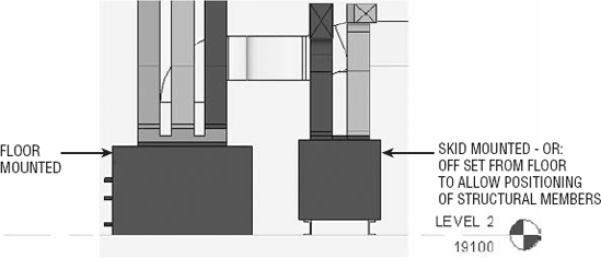
Placing the majority of AC/AHUs generally happens on the level that they are inserted on, with no offset. This can depend upon whether the unit is mounted on rails and whether those rails are part of the AC/AHU family (see Figure 10.5).
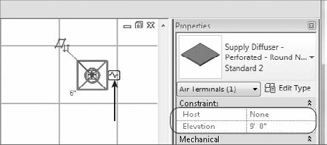
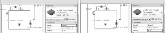
Generally created as nonhosted families, VAV boxes are usually mounted somewhere within the ceiling void, suspended from the underside of the slab above. In terms of placement, these are given an offset. One of the nice enhancements in Revit 2011 is that with the persistent properties box, the offset can be predefined, prior to the VAV (in this case) being placed. This makes for a much better workflow than previous releases where most objects were placed on the reference level and then subsequently moved to the correct invert level (see Figure 10.6).
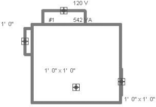
Connections to both AC units and VAV boxes can include heated and chilled water services and electrical for connecting to water and electrical systems (see Figure 10.7).
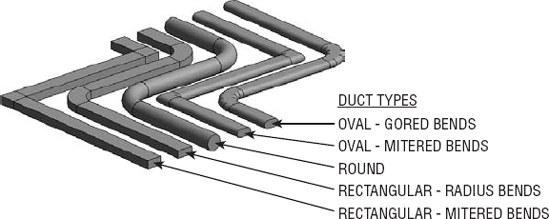
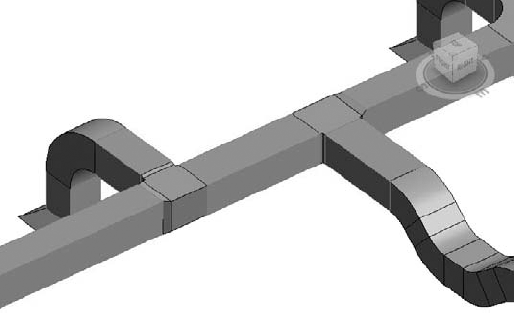
Ducts can be displayed in a variety of ways, including rectangular, round, or oval, as shown in Figure 10.8.
Ductwork is a system family and is the glue that holds systems together, but it also depends upon standard families to create a duct type, as described in the next section. Although ducts hold a huge amount of information, for the user, there are several important considerations to note.
First, ductwork and its associated fittings are systemless — they do not form part of a system until connected to points on mechanical equipment or air terminals. Figure 10.9 shows two ways in which duct can become associated with a system once connected to equipment.

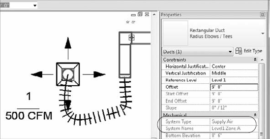
Second, a named system will be more efficient in the design environment than the default setting (see Figure 10.10). This is because elements associated with systems aid the correct flow of data throughout the model, ensuring that analysis tools such as duct sizing work to the optimum. Ensure that systems are adequately named. This aids the designer and drafter in locating systems and objects related to them. An example of this is when you have a floor that is divided into zones; a system could be called Level 1 Zone A (see Figure 10.11).

Third, when running an interference check, know that duct insulation will not form part of the calculation (see Figure 10.12) when only one interference has been detected.

Creating new duct types is a way of managing how your duct runs work and connect into each other, such as whether bends are mitered or radiused. Although you can retrospectively change any of the fittings inserted, it is much easier to create a run in one go, using either the automatic or manual tools.
Although it may be tempting to create types such as Extract and Supply, try to keep these names more specific, such as Stainless-2D Radius/Taps or Galvanized-Mitered/Tees. This way, the user only has to think about what material the duct is. Although using a name that specifies Supply or Extract may be initially attractive, doing so can lead to ambiguity and misunderstanding among the modeler, designer, engineer, and potentially the client. Another downside to this is the need to create multiple types of bends, tees, crosses, and so on, for all the different material type and system types you are likely to use.
Mike has been given the task of preparing a schematic ductwork layout for mechanical engineer Steve. Because the design architect has yet to supply a BIM model, he has some initial 2D AutoCAD plans and sections. Steve completes a rough design on paper along with calculations for duct sizes. When Mike starts the job, he links the AutoCAD section into a new section view. From here he can create building levels based on the section. With this done, floor plans are created, and the AutoCAD plans are linked into the relevant levels. Mike can now create a single-line, schematic layout for the project. At this stage, floor offsets, downstand beams, and coordination between services almost can be ignored, because the duct is being shown only as a single line. The main benefit of this is that the bulk of modeling for the duct system can be achieved at an early stage of the project and retained/modified as the project progresses.
When using the automatic routing tools, as a rule of thumb, you should work on small sections — all the feeds to a VAV box is one good example. This means the computer has fewer objects to calculate, and the routing suggestions have less room for error. Before even starting this process, check the options under Mechanical Settings (see Figure 10.13) for default duct types, offsets, and length of flex duct, because these are used during the routing process.
Now you're ready to use automatic duct routing. Here's how:
Place your VAV box, ensuring it is located at the correct height. You can change it later if needed, but this may lead to you changing your duct route.
Place your air terminals. At this point, it is a good idea to consider the following, not from a design point of view but from a Revit one:
What type — if any — are the ceilings?
If there are ceilings, should you use face, ceiling, or unhosted families?
Are you going to create your own placeholder ceiling to host your families?
Should you use the new ability to copy/monitor the air terminals already placed by the architect?
Choose the type of air terminal — is it top, side, or even sidewall entry?
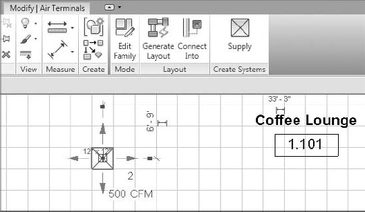
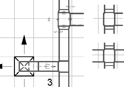
Once you've made all these decisions, it's time to start laying out the equipment. Figure 10.14 shows a space where the upper limit of the space has been defined as the level above (1), the specified supply airflow has been entered manually (2), calculated supply airflow (3) is not computed because the analysis tools have not been used for this building, and the flow rates for the air terminals have been adjusted to suit the calculation (4).
Select one of the air terminals, and on the ribbon, click Supply on the Create Systems panel (Figure 10.15).
Figure 10.16 shows the option for choosing a suitable name for the system and then adding to the system. Objects that are not part of the current system appear in halftone, but because they are selected, their appearance changes to full weight.
Once you have completed adding air terminals, click Select Equipment, and either select the equipment from the Options bar drop-down or select the actual VAV box indicated on the plan, as in Figure 10.17.
Complete this task by clicking Finish Editing System. This is where the fun begins!
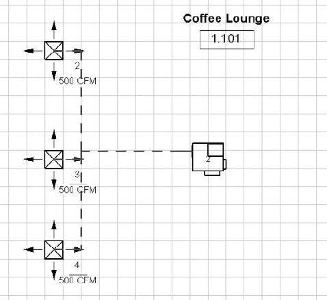
Hover over one of the items in the system (but do not select it), and press the Tab key. All the items in the system, air terminals, and the VAV box should now be connected with a dotted line (see Figure 10.18).
If you now click one of those objects in the system, the dotted lines turn red in color. This indicates that you have selected the system, not the objects themselves. The properties of the system will appear and can be edited in the Properties palette.
As shown in Figure 10.19, you can now see the Generate A Layout option.
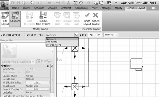
There are now several options for automatically generating your duct layout, including the Network, Perimeter, and Intersection options. Each of these options can give you several solutions that can vary depending on predefined settings for the duct layout, which can also be accessed from the Options Bar. In Figure 10.20, you can click the Edit Layout button to make further changes to the layout.
Main duct runs are shown in blue, while branch runs are green. Once you have settled on your preferred layout, click Finish Layout, and the duct layout is created (see Figure 10.21).


It's worth pointing out here that the sizes used for this layout are based on the connection sizes and the settings for duct sizes located in the Mechanical Settings dialog box. There is another important consideration at this point. The designer/drafter must ensure that the default settings for the main and branch ducts are adequately high enough above the air terminals and associated equipment to generate the layout; otherwise, the layout tool will crash.

For the experienced design drafter, using the automatic tools may seem to be too limiting; however, through use, most users eventually settle for a variety, sometimes for no better reason than a "change is as good as a rest." Sometimes, however, the manual tool is much more efficient, especially when connecting different areas into a system or laying out runs back to a rooftop AHU.
To begin manual duct routing, do the following:
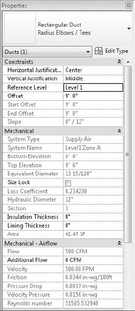
Click the Duct tool on the Home tab on the ribbon, and then choose the type and its various options from the Properties box, as shown in Figure 10.22.
Note the default settings for constraints, including Justification, Ref Level, and Level offset. The System type is undefined, and as the duct is unconnected, the airflow is 0.
You can adjust additional properties from the Options Bar and the Modify/Place Duct tab.

The duct can then be created/drawn to whatever path you choose. For vertical offsets, type the new height into the offset box on the Options Bar, but for angled setup/down, it is best to work in an elevation or sectional view.
For this example, the duct has been split into sections.
Hover over one end of the duct, right-click the connector, and select Draw Duct. Draw your duct, selecting the preferred route.

Using tools like the Trim command, you can complete the run as in Figure 10.23 and Figure 10.24.
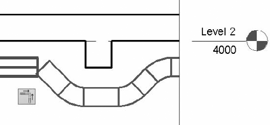
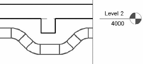
When creating ducts that set down/up or rise/drop, it is much easier to model these in a sectional or elevational view (as in Figures 10.23 and 10.24). To do this, first you need to create a suitable view. (Quite often individuals have a "personal section" that they move around the model. It can be opened when required, and then the duct — or whatever service being worked on — is modified, and the view is closed.)
To extend the design (Figure 10.25), select one of the fittings (typically bends and tees). You will notice a small plus sign (+) adjacent. Clicking this will turn a bend into a tee and a tee into a cross, eliminating the need to delete fittings and inserting an appropriate one.
The most important factors to consider when using the duct sizing tools are that the ducts form part of a system and that this system should have a nominated name, not a default, which is created at the same time as the system being created. The system must also have a valid air flow, so either you specify the airflow of the air terminals or that flow is specified from the space and volume calculations.
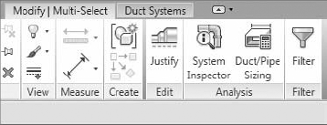
Use the Tab key to select your system (Figure 10.26).
With the system selected, you are now able to use the Duct/Pipe Sizing Tool (Figure 10.27).
Figure 10.28 shows the options available when using the Duct Sizing Dialog tool.

Although the sizing method you choose can be applied to an entire system, this is not necessarily the most efficient way to do things. If there are 5,257 objects in your system, it's probably not a great idea to ask your computer to process that amount of information — it may take a while! The logical choice is to split the task of duct sizing into manageable sections, such as a floor plan, a zone, or a group of air terminals fed from the same VAV box.
The various methods for sizing are as follows:
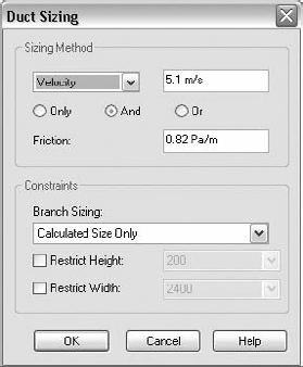
Friction and Velocity can be used independently of each other, when using the Only method. Alternatively, they can be used in conjunction with each other with the And and Or functions.
These allow the designer to force the sizing ducts to meet the parameters specified for both Velocity and Friction. With the Or method, the least restrictive of either of the parameters is used.
The Equal Friction and Static Regain methods use the ASHRAE Duct Fitting Database.
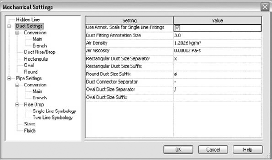
Air properties are set in the Mechanical Settings dialog box, as are the sizes of ducts used in the actual sizing calculations (Figure 10.29 and Figure 10.30).

During the sizing process, you can also apply constraints to the branch parts of the run. These are defined as follows: Calculated Size Only, Match Connector Size, and Larger Of Connector And Calculated (Figure 10.31). Depending on the stage of the design or your actual role (such as consultant), you could choose to select Calculated Size Only, because the design is still in early stages and equipment is Generic.
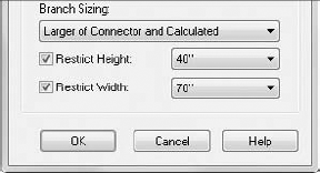
However, later in the project or as a contractor, when the equipment has been specified, you may want to select Match Connector Size and Larger Of Connector And Calculated to reduce the number of duct sizes used on the project, reducing your manufacturing costs.
This also allows you to specify a limit on the size of the ducts, which can further reduce costs or give you the ability to specify, say, a continuous duct height where you know access is a potential issue.
When designing your system, you should be aware that Revit does not take into consideration external or internal insulation in sizing calculations or in clash detection. Duct insulation does not form part of any interference checking, so although you can see the clash, it does not get reported. In addition, duct lining can be shown on the plan but does not affect the airway size. These factors may be important, especially in areas where accessibility is an issue; the designer should be extra vigilant in these situations.
Lining and Insulation can be added only as instance parameters, so if the system depends upon a lined or insulated duct, the user will have to select all ducts for the system and then specify the insulation or lining required. This would also have to be done to elbows, tees, and so on. One tip here is to apply the required insulation in a schedule (Figure 10.32).
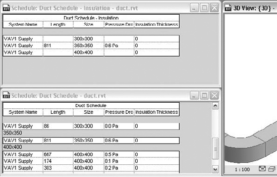
In this example, there are two schedules, one showing the system you are modifying, with all the ducts (Figure 10.33). The other is a duplicate but doesn't show All Instances (Figure 10.34). When you type in the required insulation thickness, rather than it being applied to only one section of duct, it applies to all ducts of the same type in that system.
Duct sizing will work only where air terminals, ducts, duct fittings, and mechanical equipment are seamlessly connected, with no gaps, and where the equipment has a defined airflow. This airflow could be entered as part of the initial analysis or subsequent manipulation of the objects. If you are using Revit to do your documentation process without using the analysis and design tools, then all duct sizing will need to be done manually.

Multinational Consulting and Engineering company Beca Carter Hollings and Ferner, based in Auckland, New Zealand, planned to roll out Revit MEP to their engineers and drafting staff. Although there is a strict implementation process, offices around the country and farther afield take hold of the reins and give them a good shake. While the engineers are getting familiar with the design tools, Beca decides to develop Revit to provide documentation for projects and train its drafting staff to achieve this end.
With Revit Architecture rapidly becoming the documentation and virtualization tool of choice, the next logical step is for building services. With this process relatively new to Beca, the decision was made to complete documentation in new projects using Revit MEP in areas where a high level of coordination is required. In circulation and office areas where coordination, although important, is not critical for the consulting engineer, traditional 2D drafting methods are still employed.
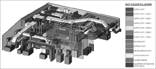
On a new hospital project, Beca uses this technique to construct major plant areas. Very quickly the company discovers the value of this high level of coordination as the complex plant areas become extremely crowded. The image shown here indicates only the ductwork in this area (for a larger, color image, refer to the website file cs1001.jpg). Interference checking is used within Revit during the documentation process to ensure services are missing not only each other but also architecture and structure elements.
With design still being done in other software, modeling the plant areas with Revit MEP enabled Beca to concentrate on utilizing new software to its optimum without committing additional untrained staff to an untested environment.
- Distinguish between hosted and nonhosted components
Deciding whether hosted or nonhosted components are used is crucial for the success of your project. It will play a large factor in performance and coordination with other companies.
- Master It
Should you choose hosted or nonhosted components for your project?
- Use the different duct routing options
When using Revit MEP 2011 for your duct layouts, the user must understand the functions of automatic duct routing and manual duct routing. Once these functions are mastered, then the user can lay out any type of ductwork system.
- Master It
When asked to submit a design proposal for a multifloor office building, the HVAC designer needs to show a typical open plan office and the supply and extract ductwork. How should the designer start this process?
- Adjust duct fittings
Duct fittings are needed in systems to make the systems function properly and to produce documentation for construction. Being able to add or modify fittings can increase productivity.
- Master It
You have just finished your modeled layout and given it to your employer for review. Your boss has just came back and has asked you to remove a couple of elbows and replace them with tees for future expansion. What would be your method to accomplish this quickly?