Routing plumbing piping has come a long way from drawing circles and lines on paper. Over the past 20 years, tools such as the straight edge, 30/60 triangle, and Timely template have been replaced by CAD systems. With more owners requiring BIM, a plumbing designer has to become a virtual pipe installer. Instead of just drawing circles and lines, you have to understand more about how fittings go together to construct your piping design. This is where Revit MEP 2011 excels; it can help you create your designs more accurately and efficiently.
In this chapter, you will learn to
Customize out-of-the-box Revit plumbing fixtures for scheduling purposes
Use custom plumbing pipe assemblies to increase speed and efficiency in plumbinglayouts
Adjust and use the plumbing pipe settings
Select and use the best pipe routing options for your project
Adjust pipe fittings
Adjust the visibility of pipes
Plumbing fixtures are as important to the look of an architectural design as granite countertops or marble tile. Plumbing fixtures, when properly selected, will not only enhance the visual design but will also promote cleanliness and hygiene. Plumbing fixtures normally are placed by the architect during schematic design to coordinate usability and meet the requirements of governing codes. From a plumbing design point of view, there are some different criteria that must be examined. What are the water conservation guidelines? Are the plumbing fixtures required to meet LEED standards? Other questions should be asked during design, such as do you as the designer want to use the plumbing fixtures that the architect has used in their model to connect your piping to, or will you substitute them with your company standard? If so, do you need to apply shared parameters that reflect the design standards required? For example, in the United States, there are two major plumbing codes: Uniform Plumbing Codes and International Plumbing Codes. To further complicate matters, some states will adopt one of these two codes and then add their own amendments, creating their own state code.
With Revit MEP 2011, you can apply this information through the use of parameters. This can be done in a couple different ways. First you can edit the information in the family itself by selecting a plumbing fixture family and editing the information through type properties (refer to Figure 15.1).

The second way to edit the information is to create a type catalog. Using type catalogs allows the user to easily produce more information about different types or models of the same family. For example, most manufacturers of bathrooms use model numbers to show the differences in finishes, rough-in locations, handle locations, and handicap accessibly information. Also, this will allow for the plumbing design to be easily changed from one manufacturer to another.
The easiest way to create a type catalog is to first open a plumbing fixture family and then review and make note of the type properties you want to be able to modify. Then create a .txt file that will populate the information. To create this .txt file, do the following:
Open Microsoft Excel. (If you do not have Excel, then you can use Notepad or Open-Office.org to achieve to same goal. OpenOffice can be downloaded from
www.openOffice.org.) Save the spreadsheet as a comma-separated values (CSV) file, making sure to name it the same as the plumbing fixture's family name.Now leave cell A1 blank; this is necessary for the type name of the family, such as Kohler or American Standard, to be listed in column A properly.
Next you will add the parameter name followed by the parameter unit in row 1. For this example, you will be using the following system parameters from the identity data located in the plumbing fixture family:
Keynote
Keynote##other##
Model
Model##other##
Manufacturer
Manufacturer##other##
Type Comments
Type Comments##other##
URL
URL##other##
Description
Description##other##
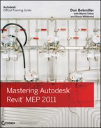
Add the information for each row that you want to be able to schedule (refer to Figure 15.2).
Once everything has been input, save the file. Make sure when the file is created, it is located in the same directory as the family it references.
Next go to the directory where you saved your file, and rename the extension from
.csvto.txt. To review what the.txtfile looks like or to make quick edits with converting back to a.csvfile, you can open this file with Notepad (refer to Figure 15.3).
If you created your file properly, you should see a catalog of information when inserting the family (refer to Figure 15.4).
Now that you have information added to your plumbing fixture family and you have placed the plumbing fixtures into the plan, you will want to schedule that information.


To accomplish this, go to the Analyze tab on the ribbon, and then select Schedule/Quantities. This will open the New Schedule dialog box. Select Plumbing Fixtures from the Category group, and then click OK (refer to Figure 15.5).

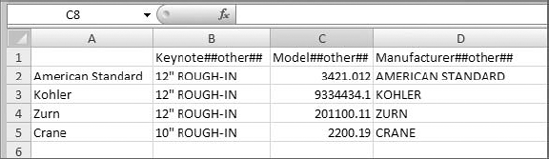
Next select the information from the Available Fields dialog box and add it to theSchedule fields (in order) dialog box. Then click OK, which will create your schedule (referto Figure 15.6).
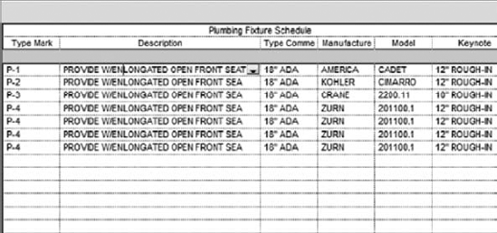
Now that you have the Plumbing Fixture schedule created, you may not want to see duplicate information or blank information, so you will need to sort the information. To do this, go to the Properties palette, select Sorting/Grouping, change the Sort By pull-down menu to Type Mark, and then deselect the Itemize Every Instance check box. Now your schedule will show only the items that have information (refer to Figure 15.7).
When using Revit MEP for plumbing, there is a gray area of how to coordinate plumbing fixtures between architectural linked in models and plumbing models. The main thought is to place the plumbing designer's edited plumbing fixtures over the architectural plumbing fixtures. In fact, Autodesk has added a new feature to Revit MEP 2011 that will allow the plumbing designer to copy/monitor the architectural plumbing fixtures. The designer has the choice of using the architectural-supplied plumbing fixtures or replacing them with the designer's plumbing fixtures that have already been edited with proper connectors and scheduling information.
To use this method of copy/monitor, the plumbing designer must turn off the plumbing fixtures on the linked architectural model so that the plan does not show double fixtures. Following this method without constant coordination review can lead to costly mistakes because the Copy/Monitor feature does not automatically update to show the new fixtures that the architect may have added. We'll talk more about this later in the chapter.
The other option is to create custom pipe assemblies. Custom pipe assemblies are fittings preassembled or modeled to line up in the locations of the linked architectural plumbing fixtures. These are created using the plumbing fixture families.
Custom pipe assemblies can be represented one of two ways in the Family Editor. First they can be represented by using sweeps to represent the p-trap, wye, and associated piping, which creates a smaller file size and will reduce the size of the overall plumbing model but is not as accurate for quantity takeoffs. Refer to Figure 15.8.

The second is assembling nested families, which can allow for better quantity takeoffs for all the fittings, can create more accurate dimensional information when supplied by manufacturers, and can be easier for the plumbing designer to create. The downside is that it will produce a larger family file. The second option will help you achieve more of the building information modeling status while helping to increase productivity. Refer to Figure 15.9.
Now let's examine how nested piping assemblies are put together and some key areas to be mindful of:
Open the
PR-Sinks and Lavs.rfafile found onwww.wiley.com/go/masteringrevitmep2011.Several different modified pipe fitting families are nested into this family that make up the assembly. They are Trap
P - PVC-DWV.rfa, Tee Sanitary-PVC-DWV.rfa,PVC-DWV Pipe Section.rfa, Plug-PVC-DWV.rfa, Elbow -Copper Type L.rfa, andCopper Type L Pipe Section.rfa. These can all be found onwww.wiley.com/go/masteringrevitmep2011, or you can get the originals from the Pipe Fitting directory located in the Imperial Library.When placing the fittings together, make sure to align, lock, and dimension each fitting together. If not, the fittings will pull apart. Refer to Figure 15.10.
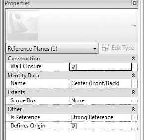
When creating your pipe assembly, make sure to set a measurement from your Sanitary piping to the reference plane Front/Center. Next click the Reference plane, go to Properties, and select the Wall Closure box located under Construction. This will allow the assembly to act as if it is a wall- or face-hosted family without all the issues that come along with those family types. The wall closure will also come in handy later in this chapter for another purpose. Refer to Figure 15.11.
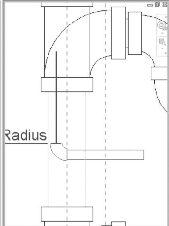
You can add parameters to flex your piping to align it under a sink or lavatory or to give a certain depth to account for floor slab. You can make these as complex or as simple as you want. Refer to Figure 15.12.
Make sure when adding a water piping connection to a rough-in pipe to add an elbow pointing in the direction of the pipe routing such as from the floor or from the ceiling. This will help with autorouting and manual routing. Refer to Figure 15.13.


Now that you have reviewed some of the items that make up a pipe assembly, you can place the pipe assembly family in your plumbing model and align it with the architectural plumbing fixtures without having to turn them off. If the architect adds a plumbing fixture, you now have the capability to visibly see the added fixture. By following this workflow, you can have the intelligent plumbing fixture on the architectural model and still tag and schedule through the architectural link.
Now let's take it a step further. If the plumbing fixtures that the architects are using match the same orientation of your pipe assemblies, you can copy/monitor the pipe assemblies directly behind the plumbing fixtures. Now when your architect moves a plumbing fixture, you will receive a warning that you need to coordinate your view. You will also have the capability to copy and change all of the plumbing fixtures on multiple levels all at one time. This can be a huge time-saver.
To use copy/monitoring, do the following:
Select Collaborate

In the Copy/Monitor panel, select Batch Copy. Click Specify Type Mapping Behavior & Copy Fixtures. Once you click this button, you will be taken to a Coordination panel that has Category and Behavior selection tables.
Select Type Mapping, and replace the plumbing fixtures from the architects with the ones you created.
If you created your piping assemblies with Wall Closure selected and proper pipe locations, you will be able to host these with nonhosted, face-hosted, and wall-hosted fixtures. Refer to Figure 15.14.
Next select Copy, and select the plumbing fixtures you want to copy. Refer to Figure 15.15.
If you are doing multiple floors, you can select all levels from the elevations view and then filter and select only the plumbing fixtures. Then select Finish.


If you highlight the assembly, you should see the monitoring symbol on the assembly. Refer to Figure 15.16.

To fully take advantage of copy/monitoring, you will need to coordinate all of your plumbing fixtures with your pipe assemblies, but you will find it is time well spent.
When setting up piping to route, you will want to apply the proper pipe material so that quantity takeoffs can be easily scheduled and to verify that the proper material is being used for the proper system. There are several areas you will have to adjust to set this up properly. These areas are system pipes, fittings, pipe material, pipe sizing tables, and fluids table, each of which is described here in more detail. Once you set these areas, you can then concentrate on autorouting and manual routing of pipe.
- System pipes
These are the pipes that are hard-coded into Revit. You have a limited amount of freedom to adjust parameters for these system families.
- Fittings
These can be applied to the parameters of the system pipes, which will allow for fittings to populate the model automatically. The fitting must be loaded into the model for them to work.
- Pipe material
This is set by selecting Mechanical Settings
- Pipe sizing table
This is set by selecting Mechanical Settings
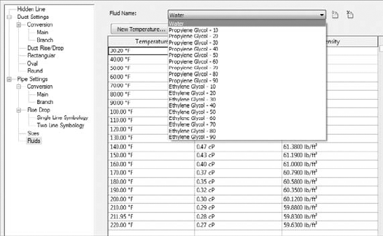
- Fluids table
This is set by selecting Mechanical Settings
To modify and create new system pipes, go to the Project Browser, and select Families

Now that you have your pipe types created, you will want to change some of the parameter options. First right-click the pipe you want to edit, and select Properties. This will open the Pipe Type parameters. Under Mechanical, you will find Material, Connect Type, and Class parameters. Change these settings to the appropriate types (refer to Figure 15.18).

Under the Identity Data parameter group, the following parameters are available: Keynote, Model, Manufacturer, Type Comments, URL, Description, Assembly Description, Assembly Code, Type Mark, and Cost.
If you have a certain manufacturer, model, or other special note that you may want to denote on the plans, you can use these settings to further describe your pipe type (refer Figure 15.19).
Under the Fitting parameters, you'll find Elbow, Preferred Junction Type, Tee, Tap, Cross, Transition, Union, and Flange. Before you can adjust the rest of your system pipe type parameters, you need to create the fittings that go with your system pipe types. To accomplish this, you must go to the Project Browser and select Families


Once you have all your pipe fittings, go to the Mechanical parameters to find the Material, Connect Type, and Class parameters. Change these settings to the appropriate types. Also, you may need to modify the Loss Method parameter to K Coefficient From Table. Also verify that the table is set to the appropriate setting (refer to Figure 15.21).

Once the pipe fittings have been created, go back to the Pipe type parameters, and under Pipe Fitting, select the proper pipe fitting for your pipe type. Doing this will allow you to be able to filter and schedule piping for quantity takeoff purposes to achieve more accurate pricing (refer to Figure 15.22).

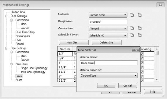
To get to the Pipe material settings, select Home

Routing piping above ceilings, in walls, in chases, and under slab is always a concern for a plumbing designer. In fact, we used to focus so much on routing piping that we would feel like the whole project would fail if one section of piping was not routed just right. We were complaining that the structural engineer's concrete beams were too big in the first-floor ceiling space and how that would affect the gravity flow of the sanitary piping. He retorted that gravity affects buildings and people can die if the building falls. But we sleeved his beam to route our piping anyway. If the building falls, no one will call about your piping design, but if the toilet won't flush, then everyone knows your name. Now using Revit MEP 2011, you can show your concerns with color-coded visual coordination and interference checking—tools that can help you avoid putting a sleeve through a structural beam. There are a couple of routing options when you set out to design your piping model: the autoroute option, the manual routing option, and the sloping pipe option. Each of these is described in the following sections.
We hope you have everything set up in your pipe types to begin routing piping. The smaller a system, the more beneficial the autoroute feature. If you have a large system you are designing, then manual routing will benefit you more because of the nature of designs changing more often. To start, open Chapter 15 plumbing.rvt and Chapter 15 base.rvt found on www.wiley.com/go/masteringrevitmep2011. Next do the following:
Select one of plumbing fixtures that you have added to the plumbing system, and press the Tab key until the autorouting features highlight its suggested path.
Select Generate Layout
You have four options to select for generating the layout: Network, Perimeter, Intersections, and Custom, and each one has several routing solutions to choose from that consists of a main (blue) and branches (green):
- Network
This solution creates a bounding box around the components selected for the piping system and then bases several solutions on a main segment along the center line for the bounding box, with branches coming from the main segment.
- Perimeter
This solution creates a bounding box around the components selected for the system and proposes several potential routing solutions. You can specify the Inset value that determines the offset between the bounding box and the components. Inset is available only when the Perimeter option is selected.
- Intersections
This solution bases the potential routing on a pair of imaginary lines extending from each connector for the components in the system. Perpendicular lines extend from the connectors. Where the lines from the components intersect are potential junctions in the proposed solutions along the shortest paths.
- Custom
The solution becomes available once you begin to modify any of the other solutions.

Selecting Fixtures When Autorouting
When using the autorouting feature, the number-one mistake that everyone makes is to try to select every fixture at one time, this will always lead to failure. The process is to use the Add And Remove From System ribbon of the General Layout ribbons.

By making the autorouting smaller, you can actually modify the runs better. Do this by removing all the fixtures from the Path Layout tool except for the few you want to connect.
Place a base to show the end of the run. Make sure this offset is at the same height as your piping, which helps ensures that you are routing your piping at the correct offset.
Once you have everything routed, connect the smaller piping systems together to make the overall system.
Manual routing of piping is the next method. The advantage of using this option is that the designer has total control over workflow. When routing manually, start your piping out at the elevation that you know will be most likely out of the way of other disciplines. Cutting sections when routing piping can really improve the success of your coordination of your Revit model. Normally we will route our mains first so we can make sure that most of the piping will fit before connecting all the branches to the mains. To route piping, select Home

Before repeating this process for all of your plumbing systems, take some time to review the structural, mechanical, and architectural models. This can really cut down on modeling time. After coordinating the pipework and verifying the design flow rates, the layout is complete.
Whether you created your plumbing piping layout with autorouting or manual routing, you need to see whether your piping is reading flow. By using the Pipe Inspector, you can verify if your piping is well connected. To use this tool, click a piece of pipe that has been routed in a complete system. Once the pipe is selected, you will see the Modify Pipes ribbon. From this, select the System Inspector. With the System Inspector selected, pick any section of the pipe, and you will notice the GPM of the system and a direction of flow (refer to Figure 15.27).
Now you are assured your piping is well connected.
A lot of people think sloped pipe applies only to sanitary sewer. But in most specifications, almost all piping calls for a slight slope to be in the pipe so if systems are drained down, they are less likely to trap water. Vent piping has a slope because it is open to the atmosphere because of the vent having to penetrate the roof. Storm sewer is one of the most critical systems to make sure you have the proper slope because large rain water loads have been known to make roofs collapse. Now that we have you thinking about checking your specifications to see whether you need to slope more piping than just your drainage, let's look at how you will slope your pipe.

First you select the method of how you are going to run your piping using either the autorouting or the manual routing feature. When we lay out sanitary sewer, we always like to manually route our main first to establish where the sanitary is going to be leaving the building and make sure it has been coordinated with the civil engineer.
For sloping pipe to work properly, it needs to have a starting point and an ending point. To set up sloping pipe, open Chapter 15 plumbing.rvt and Chapter 15 base.rvt. Also download sanitary point of connection.rfa and wall cleanout.rfa. All of these files are found on www.wiley.com/go/masteringrevitmep2011. Next do the following:
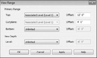
Make sure you have your view range set properly because you are going to be routing below 0'-0". To change the view range, type VP, which will open the View Properties dialog box. Select View Range, and change Bottom and View Depth to Unlimited (refer to Figure 15.28).
Next look at your routing choices for your main. Then locate your end run fixture, floor cleanout, or wall cleanout.
Next locate your sanitary point of connection outside the building locating the sanitary piping at −4'0" below finished floor.
Next select the Pipe toolbar located on the Home tab of the ribbon. Before you start routing your pipe, be sure to set the 1/8" /12" slope setting, and make sure you have the justification set to your preference.

Now start your run from the sanitary point of connect, and route into your last fixture or cleanout. You now have a main trunk to build your system off.
Select the Pipe toolbar, and then select the point on the main you want to route from. Once you do that hit the spacebar one time; this will make the piping connect at the same elevation as your pipe. Then route out to the water closets or any other components that take 1/8" slope.
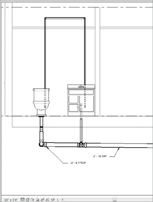
Route all of your sloped pipe that contains the same degree of slope first. Then route all of the next matching slope. Having a redundant pattern will add to your efficiency and productivity. Now you should have a sloped system (refer to Figure 15.29).
If you need to track the slope, use an elevation tag. This will allow you to find the invert of the pipe along any point of the pipe. It can be used only in elevations, sections, and 3D views. It does not account for insulation of pipe.
Without fittings, piping would not be worth a whole lot. Fittings help shut off, help regulate, help open up, and help save lives. In Revit, most fitting families have the following functions:
- End cap
These can be placed only at the end of pipe.
- Tee, tap, wye, or cross
- Transitions, couplings, or unions
These can be placed only at the end of pipe. They are used to join a smaller, larger, or same-size pipe.
- Flange
These can be placed at the end of pipe or face to face with an another flange.
Understanding pipe fitting controls can really make life easier if you are routing a lot of piping. There are several fittings that have this ability. When you are laying out your piping, turn 90 degrees to create a elbow. If you click the elbow, you will notice a plus (+) sign. If you click that sign, it will change from an elbow to a tee, allowing you to add more piping and continue your pipe routing. If you select the minus (−) sign, it will downgrade the fitting. When you see the
When you need to add valves to your piping, select the Home tab, and click Pipe Accessories. Use the Type Selector to select the type of valve you want to use. Most valves are based on "break into" type parameter, so you can place them into the pipe type, and they will break into the piping and connect (refer to Figure 15.30).
In early 2008, an AEC firm in Knoxville, Tennessee, was working on a hotel project in Pigeon Forge, Tennessee. This 90-room hotel had already gone over the estimated projected design hours because of constant changes of field conditions, and it was the first hotel produced in Revit for this firm.
The building was a conventional plumbing sanitary with traditional multiple vent stacks. The project went out for bid, and when the bids came back, the building was slightly over the estimated budget, and the design team was asked to figure a way to get the cost back into budget. After carefully reviewing the project, the plumbing designer and engineer had decided to use a PVC version of a So-Vent plumbing system; only two families would have to be created for Revit: an Aerator and a De-aerator fitting. The cast-iron version of the system has been used in northern parts of the United States in high-rise design for years successfully.
The problem faced with using a system like this was that no one had installed such a system in East Tennessee. Plumbing code officials had not seen the system installed, and they stated it did not meet traditional methods of vent design. By using a section under codes that allowed the use of engineered plumbing systems, the design team proceeded to design the system. Because the existing layout was already in Revit, it was the logical choice to redesign the system in it.
Within two working days, the model and contract documents were revised with the new layout and then rebid. One-third of the vent system was reduced, which led to fewer holes being cut, fewer manhours, and fewer fire stopping costs. Since the plumbing contractor had never installed a So-Vent system before, being able to use printouts of the 3D model helped speed up the installation of the system and assure it was installed properly.
Although the project may have lost money for the firm, the hotel owner was happy with knowing that his construction costs were within budget and that his hotel could open on time.
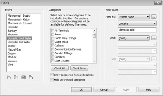
Now that you have created systems and added the piping, you need to be able to display them in different views, and you may also want them to display with different colors and line weights. If you created your systems correctly, you can go to Filters located on the View tab. Here you are able to create new filters by duplicating and modifying any of the existing ones (refer to Figure 15.31).
Once the filters have been created, go into each view where you want the different disciplines to show up, and type VG to bring up the Visibility/Graphics. Click the Filters tab, and add the newly created filters. At this point, you can control the line type, colors, and patterns of the filtered objects to match your company standards. Refer to Figure 15.32.

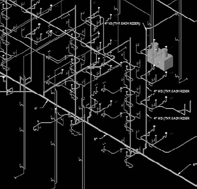
Now that your plans are coordinated and displaying the way you require, you are well on your way to completing your documentation. Also consider using the same filters to display 3D views, which can enhance the design, making it easier to understand and further reducing errors. Refer to Figure 15.33.

- Customize out-of-the-box Revit plumbing fixtures for scheduling purposes
Learning how to customize existing plumbing fixtures can help with productivity and provide more robust building information.
- Master It
What are the two types of parameter information that can be scheduled and used in type catalogs?
- Use custom plumbing pipe assemblies to increase speed and efficiency in plumbing layouts
Sometimes you are required to think outside the box and learn how to use new tools to get the most benefit out of them. By utilizing the new Copy/Monitor feature when creating custom pipe assemblies, you can take production to the next level.
- Master It
Why are nested pipe assembly families better to use than the modeled pipe assembly for a BIM project ?
- Adjust and use the plumbing pipe settings
Piping settings are crucial to the ability to have Revit MEP model your plumbing layout, the way it will look, and the way it will perform.
- Master It
Do fitting parameters have to be set up in the system pipe types?
- Select and use the best pipe routing options for your project
When using Revit MEP 2011 for your plumbing layouts, you must understand the functions of auto pipe routing, manual pipe routing, and sloping pipe. Once these functions are mastered, then the user can lay out any type of piping system.
- Master It
A plumbing designer has just been asked to lay out a sloped plumbing system and has only a day to pipe up a clubhouse. Where should he start his pipe route first?
- Adjust pipe fittings
Pipe fittings are needed in systems to make the systems function properly and to produce documentation for construction. Being able to add or modify fittings can increase productivity.
- Master It
You have just finished your modeled layout and given it to your employer for review. He's just came back and now has asked you to remove a couple of elbows and replace them with tees for future expansion. What would be your method to accomplish it quickly?
- Adjust the visibility of pipes
Being able to adjust the visibility gives the plumbing designer or user the ability to set up multiple views and control the graphics for documentation.
- Master It
There are too many systems showing up in your views. What would you do to show only one piping system in that view?