Mechanical piping is the lifeblood of a heating/cooling system. If not piped correctly, it can lead to problems in the field, and locating them may take months. There are simple two pipe systems and more complex multipipe systems. When using Revit MEP 2011 to lay out your systems, you will be able to very easily see your routing options and even calculate the total volume of fluid in your system.
In this chapter, you will learn how to
When setting up the mechanical piping to route, you will want to apply the proper pipe material. The purpose of this is to provide a more accurate layout by showing the correct pipe sizes and fittings for that system. You will have to adjust several areas to set this up properly. These areas are system pipes, fittings, pipe material, pipe sizing tables, and the fluids table, each of which is described here in more detail. Once you set these areas, you can then concentrate on the autorouting or manual routing of pipe.
- System pipes
These are the pipes that are hard-coded into Revit. You have a limited amount of freedom to adjust parameters for these system families.
- Fittings
These can be applied to the parameters of the system pipes, which will automatically populate the pipe system and the model. The pipe fittings must be loaded into the model for the system to work.
- Pipe material
This is set in Mechanical Settings

- Pipe sizing table
This is set in Mechanical Settings Sizes. This allows you to duplicate and adjust inside pipe diameter, outside pipe diameter, and pipe sizes to the manufacturer's specifications.
- Fluids table
This is set in Mechanical Settings
To modify and create new system pipes, in the Project Browser select Families

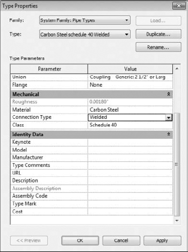
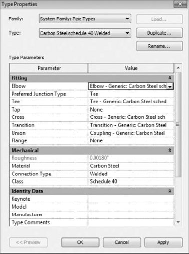
Now that you have your pipe types created, you will want to change some of the parameter options. First right-click the pipe you want to edit and select Properties. This will open the Pipe Type parameters. Under Mechanical, you will find Material, Connect Type, and Class parameters. Change these settings to the appropriate types. (Refer to Figure 11.2.)
Under the Identity Data parameters group, the following parameters are available: Keynote, Model, Manufacturer, Type Comments, URL, Description, Assembly Description, Assembly Code, Type Mark, and Cost. If you have a certain manufacturer, model, or other special note that you may want to denote on the plans, you can use these settings to further describe your pipe type. (Refer to Figure 11.3.)
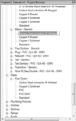
Under the Fitting Parameters group, there are Elbow, Preferred Junction Type, Tee, Tap, Cross, Transition, Union, and Flange settings. Before you can adjust the rest of your system pipe type parameters, you need create the fittings that go with your system pipe types. To accomplish this, you must go to the Project Browser and select Families Pipe Fittings. Once you are under Pipe Fittings, you'll want to select the fittings that will be required for your pipe type parameters. You will right-click each of the family fittings and duplicate standard generic Elbow, Cross, Coupling, Tee, and Transition. After duplicating each one of these, rename them to the associated material of each pipe that you previously duplicated to create your pipe types. (Refer to Figure 11.4.)

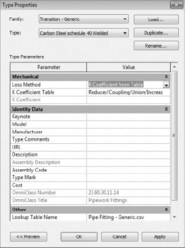
Once you have all your pipe fittings, go to the Mechanical parameters to find parameters for Material, Connect Type, and Class. Change these settings to the appropriate types. Also, you may need to modify the Loss method to K Coefficient From Table; also verify that the table is set to the appropriate setting. (Refer to Figure 11.5.)
Once the pipe fittings have been created, go back to the Pipe Type parameters, and under Pipe Fitting select the proper pipe fitting for your pipe type. Doing this will allow you to filter and schedule piping for takeoff purposes. (Refer to Figure 11.6.)
To get to the pipe material settings, go to Home

If you want to adjust the sizing table, go to Home

The size of mechanical piping can grow quite large because of the amount of fluids constantly transferred, so it is very important that routing is closely coordinated. Now using Revit MEP 2011, you can show your concerns with color-coded visual coordination and use interference checking to monitor conflicts with cable trays or sprinkler piping. There are a couple of routing options when you set out to design your piping model: the autoroute option and the manual routing option. The smaller a system, the more beneficial the autoroute feature. If you have a large system you are designing, then manual routing will benefit you more because of the nature of designs changing more often. Each of these is described in the following sections.
Ideally you have everything set up in your pipe types to begin routing piping. To start automatic pipe routing, select one of pieces of mechanical equipment that you have added to the mechanical piping system. Next press the Tab key until the autorouting feature highlights its suggested path. Then you can select Generate Layout

You have four options to select for generating the layout: Network, Perimeter, Intersections, and Custom, and each one has several routing solutions to choose from that consist of a main (blue) and branches (green):
- Network
This solution creates a bounding box around the components selected for the piping system and then bases several solutions on a main segment along the center line for the bounding box, with branches coming from the main segment.
- Perimeter
This solution creates a bounding box around the components selected for the system and proposes several potential routing solutions. You can specify the Inset value that determines the offset between the bounding box and the components. Inset is available only when the Perimeter option is selected.
- Intersections
This solution bases the potential routing on a pair of imaginary lines extending from each connector for the components in the system. Perpendicular lines extend from the connectors. Where the lines from the components intersect are potential junctions in the proposed solutions along the shortest paths.
- Custom
The solution becomes available once you begin to modify any of the other solutions.
When using the autorouting feature, the number-one mistake that everyone makes is to try to select every unit at one time. This will nearly always lead to failure. The process is to use the Add To System/Remove From System tool that is part of the General Layout ribbons. (Refer to Figure 11.11.)

By making the autorouting smaller, you can actually modify the runs better. Make sure this offset is at the same height as your piping, because this helps ensures that you are routing your piping at the correct offset. Once you have everything routed, connect the smaller piping systems together to make the overall system.
Manual routing of piping is the next method. When routing, manually start the piping run at the elevation that you know will be most likely out of the way of other disciplines. Use the following steps to set up and place mechanical equipment, create a hydronic supply and return, and manually route pipe to all pieces of equipment.
Open the
Chapter11_Dataset.rvtfile found onwww.wiley.com/go/masteringrevitmep2011.Because of the normal size that models can grow, it is not uncommon for the architectural model to be linked into the mechanical model. Download the model Chapter 11
base.rvtfile found atwww.wiley.com/go/masteringrevitmep2011.Go to Insert
Next go to Insert
Go to Home
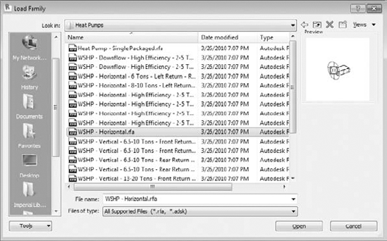
Your system will require a boiler and closed circuit cooling tower. Go to Insert Load Family Imperial Library
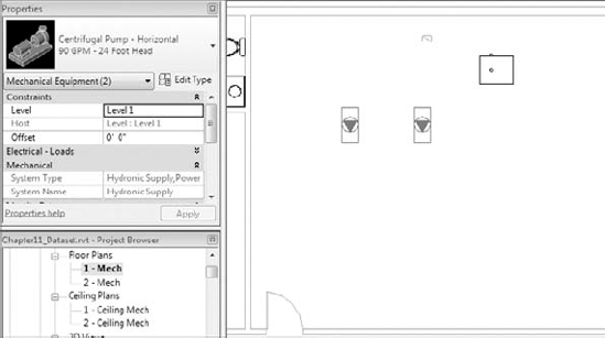
Next you will need a centrifugal pump. Go to Insert
You are now in a position to start routing piping. Route your mains first so you can make sure that most of the piping will fit before connecting all the branches to the mains. Select the proper piping material before starting your layout. This will help if you need to do a quantity takeoff for budgeting purposes. To route your pipe, select Home Pipe. Change the offset to 8′6″ (259.08cm) and pipe size to 2′ (60.6 mm), and route piping mains in the corridors and into the mechanical room. (Refer to Figure 11.17.)
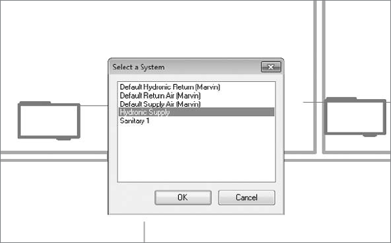
Before you start connecting piping, you will need to make sure that your mechanical equipment is set up for both hydronic supply and return systems. To do this, select one of the pieces of mechanical equipment, then go to Home
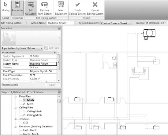
Once you have selected the hydronic return, go to the Piping Systems tab, select Edit System, and edit the Hydronic Return system name. Then select Add To System, and select all mechanical equipment that contains Hydronic Return connections. Repeat with Hydronic Supply. (Refer to Figure 11.19.)
Cutting sections when routing piping can really improve the success of your coordination of your Revit model. To route piping, go to Home
Repeat this process for all your piping systems Taking a few minutes to review any clashes between the structure, mechanical, and architectural models can really cut down on modeling time. The layout is now completed once you have coordinated between other services/structure and verified your layout.


In 2007, Michael Brady Incorporated used Revit Systems for MEP and Revit Architecture to design First Baptist Church in Farragut, Tennessee, and to produce contract documents. Because of the design timeline, the structural team used AutoCAD 2007 to lay out its structure.
Charles Merriman, the mechanical designer on the project, linked in the structural CAD plans and decided to mass objects above the ceiling space to represent the depth and location of the bar joists and beams. Although this was a little time-consuming, it helped show some of the conflicts he was facing with his design.
By using this technique, he was able to avoid some very large problems associated with the mechanical pipe routing and duct layout. When the project was in the construction phase, the general contractor began to ask for a potential change order. Charlie opened his Revit file and printed a 3D view of the area in question. Because of Charlie's earlier commitment to coordinating his design, the area in which the contractor thought was an issue was easily resolved.
Without fittings, piping would not be worth a whole lot. Fittings help shut off flow, help regulate temperature, and help save lives. In Revit, most fitting families have the following functions:
- End Cap
These can be placed only at the end of pipe.
- Tee, Tap, Wye, or Cross
These can be placed anywhere along pipe runs.
- Transitions, couplings, or unions
These can be placed only at the end of pipe. They are used to join a smaller, larger, or same-sized pipe.
- Flange
These can be placed at the end of pipe or face to face with another flange.
Understanding pipe fitting controls can really make life easier if you are routing a lot of piping. Several fittings have this ability. When you are laying out your piping, turn 90 degrees to create a elbow. If you click the elbow, you will notice a plus (+) sign. If you click that sign, it will change from an elbow to a tee allowing you to add more piping and continue your pipe routing. If you click the minus (−) sign, it will downgrade the fitting. When you see the
When you need to add valves to your piping, select the Home tab, select Pipe Accessories, use the Type Selector, and select the type of valve you want to use. Most valves are "break into" types, so you can place them into a pipe run, and it will break into the piping, maintaining connections at either end. (Refer to Figure 11.21.)

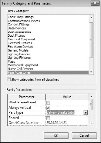
When creating or editing families, use the family parameter Part Type, which will define the ability to Breaks Into. (Refer to Figure 11.22.)
You have created systems and have joined them together with pipes, fittings, and accessories. Now you want to have them represented according to your company standards in different views. This means changing colors, line weights, line types, and the actual ability to view them at all. If the systems were created correctly, you can apply filters to your views to add this additional control. To do this, go to Filters located under the View tab and duplicate, rename, and change system type to system name. (Refer to Figure 11.23.)

Once you have your filters created, go into each view where you want the different disciplines to show up. Press VG to bring open the Visibility/Graphics dialog box. Next go to the filters and the filters you want to control, and change the line types and colors to match your company standards. (Refer to Figure 11.24.)

With the views defined, you can create a view template from the view, enabling you to ensure that all views of a specific discipline display with the same configuration. Once you have everything set the way you want the project to look, you can complete the documentation.
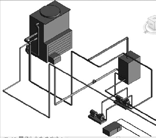
Your 3D views can also be color coded to make it easy to review piping. (Refer to Figure 11.25.)
- Adjust and use the mechanical pipe settings
Making sure that the mechanical piping settings are properly set up is crucial to the beginning of any project.
- Master It
A designer has just been asked to model a mechanical piping layout, and the engineer wants to make sure the designer will be able to account for the piping material used in the layout. What steps must the designer take to the complete this request?
- Select and use the best pipe routing options for your project
When using Revit MEP 2011 for your mechanical layouts, one must understand the functions of automatic pipe routing and manual pipe routing. Once these functions are mastered, then the user can lay out any type of piping system.
- Master It
The engineer has just come back from a meeting with the owner and architect, and it has been decided that the owner wants to have a hot water system and a chilled water system rather than a two-pipe hydronic system. How would you modify your hydronic layout to accommodate the change?
- Adjust pipe fittings
Pipe fittings are needed in systems to make the systems function properly and to produce documentation for construction. Being able to add or modify fittings can increase productivity.
- Master It
You have printed off a check set for review and have noticed that there are no shutoff valves. Now you need to load the shutoff family. What directory should you look in for pipe fittings?
- Adjust the visibility of pipes
Being able to adjust the visibility gives the mechanical designer or user the ability to set up multiple views and control the graphics for documentation.
- Master It
The engineer has just come back from a meeting with the owner and architect, and it has been decided that the owner wants to have a hot water system and a chilled water system. You have just modified your hydronic layout to accommodate the change. Now the owner wants the pipes color coded, so it's easier to visualize the changes. Describe how this would be done.