
4. Managing Layers
The Flash Catalyst Layers panel is like a master control center for designing your application. It provides an organized structure for viewing and managing every object in the artboard. With the click of a button, you direct which of those objects are present and visible in the current page or component state.
In this lesson, you’ll learn how to do the following:
• Identify target and selected layers
• Expand and collapse layers
• Show and hide objects in the current page or state
• Lock and unlock layers, groups, and objects
• Group complex object parts
• Optimize complex groups
• Add and delete layers
• Rename objects in the Layers panel
• Use layers to locate selected objects
• Change the stacking order of objects
This lesson will take about 30 minutes to complete. Copy the Lesson04 folder into the lessons folder that you created on your hard drive for these projects (or create it now), if you haven’t already done so. As you work on this lesson, you won’t be preserving the start files; if you need to restore the start files, copy them from the Adobe Flash Catalyst CS5 Classroom in a Book CD.
![]()

Layers are probably the most important workflow and design tools you have in Flash Catalyst. Using the Layers panel, you have complete control over every object in every state, including visibility and stacking order.
Exploring the Layers panel
The Layers panel shows every object in the application using a collection of stacked rows. Rows can represent layers, sublayers, objects (images, text, components, and so on), and groups (grouped objects). The target layer is always shaded light blue. Any objects that you add to the artboard are placed in the target layer. To select a target layer, just click in its row. A layer must be unlocked and visible to act as the target layer.
Tip
A collection of related objects can be grouped in Flash Catalyst or in the design document (AI, PSD, or FXG) before importing.

Note
Layers and sublayers are sometimes referred to as layer folders, because they are identified by a small file folder icon.
Expand and collapse layers
The Layers panel lets you organize your project using a hierarchy of related objects. Items are nested together into collapsible layers and groups for quick access and easy viewing.
- Start Flash Catalyst. Browse to the Lesson04 folder and open Lesson04_Banner.fxp.
- Click the Layers panel tab to bring it to the foreground.
This project includes artwork that was imported from an Adobe Illustrator file with a single artboard. The original layer structure is preserved in Flash Catalyst.
The application has ten top-level layers (layer folders), and each layer includes several objects. This project began with one new page state. Right now, all the artwork for this application is stacked together in one page state. Eventually, you will create additional pages, and then use the Layers panel to show and hide different objects in each page state. For now, let’s take a closer look at the Layers panel.
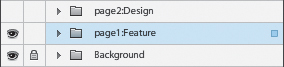
- Click the small gray triangle beside the page1:Feature layer to expand it. This is a toggle button used to expand and collapse a layer.
Note
Layer names, such as page1:Feature, were preserved from the original design document. You can change layer names to anything you want, as long as they clearly describe their contents.
The page1:Feature layer holds the artwork for Page1 of the interactive banner application. It includes several objects, including one group and one sublayer.

- Collapse the page1:Feature layer.
Show and hide layers
You control which objects appear in each page or component state by selecting a state in the Pages/States panel, and then turning on and off layers. When you first add objects to a page or component state, they are present, which means they exist in that state. When an object is present, it can be made visible or hidden using the Layers panel. The following information will help to identify the presence and visibility of objects in the current state using the Layers panel:
• Present and visible: The name of the object is listed using dark text (present), and the eyeball icon is dark (visible).
• Present and hidden: The name of the object is listed using dark text (present), but there is no eyeball icon showing (hidden). If the eyeball appears dimmed, the object’s visibility is on but its parent layer is hidden. When a parent layer or group is hidden, its children are hidden automatically.
• Not present: The name of the object is listed using dimmed text (not present). The object is not present in the current state, but it does exist in one or more other states of the application.
Try expanding and hiding the page2:Design layer.
- Expand the page2:Design layer.
You can tell that its contents are hidden because there is no eyeball icon beside the layer name. But notice that the eyeballs for each of its objects are dimmed. A dimmed eyeball means the object is turned on, but its parent layer is currently hidden.

- Take a look at the artboard.
Even though we have the artwork for Page2 stacked above the artwork for Page1, we don’t see it because its layer is turned off.

- Click the empty Show/Hide box beside the page2:Design layer in the Layers panel.
The artwork for Page2 becomes visible in the artboard and the eyeball icon appears beside the layer name.

- Click the eyeball icon beside the page2:Design layer to hide it.
Once again, the artwork for Page2 is hidden and you see the artwork for Page1. That’s what you want because you’re still working on Page1, as shown in the Pages/States panel.
- Collapse the page2:Design layer in the Layers panel.
Lock and unlock layers
With so much artwork stacked in the same space, it’s easy to accidentally select and move objects unintentionally. One way to protect your design is to lock objects when you’re not editing them. A padlock icon indicates when an object is locked.
- Click the Top Graphic layer to select it.
The Top Graphic (horizontal gray bar) is selected in the artboard and in the Layers panel. Clicking an object, layer, or group in the Layers panel selects all of its contents in the artboard, as long as the objects are unlocked.

- Click the Top Btns layer.
Nothing happens because the Top Btns layer is locked, as indicated by its padlock icon.
- Click the padlock icon beside the Top Btns layer to unlock it.
- Click the Top Btns layer again.
This time the layer is selected, along with all of its content in the artboard. If you look in the artboard, you see that you’ve selected the artwork for all five navigation buttons, with a single click. Clicking layers and groups is a quick way to select multiple related objects.
- Click the empty lock box beside the Top Btns layer in the Layers panel to lock it.
The padlock icon returns and the objects in the artboard are deselected automatically. Locked objects cannot be selected or moved.
- In the artboard, click any of the five numbered navigation buttons.
The button you clicked is not selected, but the artwork directly below it (the Top Graphic) is. This is because the Top Btns layer is locked. Flash Catalyst selects the top-most unlocked and visible object.

Grouping objects
Groups are created in the Layers panel automatically when you group objects in the original design document. This makes their parts more manageable in Flash Catalyst. You can also group related objects after importing them. This is helpful when your design includes a large collection of parts that make up a single graphic. For example a vector drawing may include hundreds of smaller paths. Grouping them makes them a lot easier to manage in the Layers panel.
- Expand the page1:Feature layer.
- In the Layers panel, click to select the Line object.
- Hold down the Shift key and click to select Transparency BG (seven rows below).
A range of eight objects is selected in the artboard and in the Layers panel.
Tip
You can also Control-click/Command-click to select a non-contiguous range of objects in the Layers panel.

- Choose Modify > Group.
The selected objects are combined into a single Group.

Renaming objects in the Layers panel
Now that you’ve grouped a range of artwork in the page1:Feature layer, there are two groups with the same name. That’s because all new groups are created with the default name, Group. This is also true when you add new images or components. Each new object in the Layers panel begins with a generic name, such as Image, Button, Scroll Panel, and so on. This can be a little confusing unless you take the time to assign more descriptive names.
Note
When you import artwork from a design document created in Adobe Illustrator, Adobe Photoshop, or Adobe Fireworks, the objects in the Layers panel are named automatically using the original layer names you provided in the design document.
- In the Layers panel, double-click the Group name you created in the previous exercise.
The name is highlighted in the Layers panel.

- Type Panel Artwork and press Enter/Return.
The group is renamed.

- Collapse the page1:Feature layer.
Note
The names you assign to layer folders, groups, and individual objects in the Layers panel are used for organizational purposes only. Changing names in the Layers panel does not affect the names of assets in the Library panel, and vice versa.
Optimizing complex groups
It’s not uncommon for the vector artwork you import into Flash Catalyst to include complex graphics that are made up of many intricate pieces. For example, an illustration may include hundreds of individual paths that are grouped to form a single image. In addition, any text that was turned into vector outlines will import with a separate path for each individual character. If you don’t need to manipulate each of these smaller parts, you can turn them into a single graphic object using the Flash Catalyst optimization options. Optimizing complex groups of artwork also makes them easier to manage in the Layers panel.
- In the artboard (not in the Layers panel), click the large orange text that reads 2 WHEELS GOOD.

In the artboard, it appears that you have a single object selected. If you look in the Layers panel, you see a small blue square in the page1:Feature layer. A small blue square means the row includes a selected object. This is useful for finding selected items in the Layers panel when not all layers are expanded. You can follow the blue boxes as you drill down to find the selected item(s).
- Expand the page1:Feature layer.
You can tell by the dark blue shading that the Group row is selected.

- Expand the Group.
The 2 WHEELS GOOD text was turned into vector outlines before importing the design document. Each character is a separate path. You don’t need to edit this text, so let’s optimize this artwork using the Heads-Up Display (HUD).

- The Group is still selected, so in the Optimize Artwork section of the HUD, click Choose Command, and choose Optimize Vector Graphics.
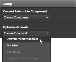
The vector paths are turned into a single object in the Layers panel named Graphic1.

- Change the name from Graphic1 to 2 WHEELS GOOD.
Adding and deleting layers
Adding new layers in the Layers panel is simple; you simply add a new layer folder. To add a new top-level layer folder, click the Create New Layer icon (![]() ). To add a new sublayer folder, select an existing top-level layer and click the Create New Sublayer icon (
). To add a new sublayer folder, select an existing top-level layer and click the Create New Sublayer icon (![]() ). Deleting layers is just as easy. Select the layer folder and click the Delete icon (
). Deleting layers is just as easy. Select the layer folder and click the Delete icon (![]() ). When you add or delete layer folders, the changes appear in every page state (or component state when editing a component).
). When you add or delete layer folders, the changes appear in every page state (or component state when editing a component).
- In the Layers panel, click the Create New Layer icon (
 ).
).
A new top-level layer folder is added at the top of the Layers panel. New layers are named Layer1, Layer2, and so on. You can rename this layer folder, just like any other object in the Layers panel.
- Select the new layer folder (Layer1), and click the Delete icon (
 ) in the bottom-right corner of the Layers panel.
Tip
To remove an object from the current state without removing it from other states, select the object and press Delete.
The new layer folder is gone. If this application had more than one page, the layer would be removed from all pages. If this layer contained any objects, those objects would also be removed from every page.
Note
If an object name appears dimmed in the Layers panel, it means the object is not present in the current state, but it does appear in another state of the application.
Stacking artwork using layers
To change the stacking order of objects in the application, you can drag rows up or down in the Layers panel. You can also change the stacking order of objects within a layer or group.
Note
The stacking order of layers is constant across all states. You can’t have a different stacking order in different states.
- Look at the artboard and notice that the orange 2 WHEELS GOOD text appears over a semi-transparent gray background.

- In the Layers panel, inside the page1:Feature layer, drag the Panel Artwork row above the 2 WHEELS GOOD row.
A gray line indicates the new location for the row when you release the mouse.

Now look at the artboard again. The orange text appears below the semi-transparent gray background and is barely visible.

- Choose Edit > Undo to return to the proper stacking order of the artwork.
- Expand the Panel Artwork layer.
To change the stacking order of objects within the same layer or group, you can drag rows in the Layers panel or use the Arrange commands in the Modify menu.
- Select the Transparency BG row in the Layers panel and choose Modify > Arrange > Bring to Front.
The Transparency BG row moves to the top of the stack, but only within its parent group. You can tell by looking in the artboard that the stacking order of these objects is important to the integrity of the design.

- Choose Modify > Arrange > Send Backward.
Each time you choose Send Forward or Send Backward the object moves up or down one row.
- Choose Modify > Arrange > Send to Back.
The Transparent BG layer moves back to the bottom of the stack, where it belongs.
- Drag the 2 WHEELS GOOD row into the Panel Artwork layer and position it at the top of the stack.

- Collapse and lock the Panel Artwork layer.
There is one last change that needs to be made to the arrangement of the objects in the page1:Feature layer. The Image row, at the top of the stack, belongs inside the Sample Images sublayer folder.
- Drag the Image row (with the picture of a man) down until it’s directly over the Sample Images row. This causes the Sample Images row to expand automatically. When it does, drag the Image row above the 2 wheels image row and release the mouse button.

The Image row is now inside the Sample Images sublayer folder.
Review questions
1 What is the target layer, and how is it identified in the Layers panel?
2 What types of items appear in the Layers panel?
3 What does a small blue square in the Layers panel indicate?
4 In a new Flash Catalyst project, why do some rows have descriptive names, while other rows have generic names, such as Image, Graphic, or Group?
5 How can you make the Layers panel more manageable when your project includes artwork, such as illustrations or text outlines, that contains several small paths?
6 How do you change the stacking order of objects in the Layers panel.
7 When you add a bitmap image from the Library panel to the artboard, a new Image is added to the Layers panel. What happens to the image in the Library panel if you rename this object in the Layers panel?
Review answers
1 You can make any unlocked and visible layer the target layer by selecting it. When you add a new object to the artboard, either by dragging from the Library panel, by importing, by drawing shapes, or by adding new text, the new object is placed in the target layer. The target layer is identified in the Layers panel by light blue shading.
2 The Layers panel shows every object in the application using a collection of stacked rows. Rows can represent layers, sublayers, objects (images, vector drawings, text, media, and components), and groups (grouped objects).
3 A small blue square means the row includes a selected object. This is useful for finding selected items in the Layers panel when not all layers are expanded. You can follow the boxes as you drill down to find the selected item(s).
4 When you create a new Flash Catalyst project from a design document you created in Photoshop, Illustrator, or Fireworks, the naming and structure of the design document is preserved in Flash Catalyst. When you add new objects in Flash Catalyst, these new objects begin with generic names, such as Group and Image.
5 Grouping complex graphics is one way to keep the Layers panel more manageable. If you don’t need to work with the individual parts of a vector graphic, you can select its parts and create a single optimized graphic. Once you do this, it becomes a reusable optimized graphic in the Library panel.
6 To change the stacking order of objects, you can drag rows up or down in the Layers panel. You can also change the stacking order of objects within a layer or group using the Arrange commands in the Modify menu.
7 There is no link between the names of objects in the Layers panel and the names of assets in the Library panel. You can change the name of objects in the Layers panel without affecting the name of the source asset in the project library.