
Meters, Monitors, and Scopes
Looks Good Here!
One of the common wisecracks in television is, “Looks good here!” It is uttered by someone who is claiming that the signal is fine at that end, and if there is a problem, it must be the fault of the person at the other end of the line. That “other end” may be down the hall from the studio in the tape room or it may be across the country after several microwave links, fiber optic runs, and a satellite hop. Regardless of how complex the ultimate link is, the fact remains that the original signal must be technically correct.
Meters
The light meter and the color temperature meter are the only tools available with which to predict the final outcome of cinematographers’ or videographers’ lighting efforts. They combine those tools with their experience to form judgments about exposure and color temperature correction. In most cases, that is enough to get the job done, and good cinematographers will rarely mess up. However, in film, they can never be completely sure of their exposures until they view the processed film. Video is more forgiving because most cameras have color viewfinders or flip-out LCD screens which enable immediate results. Studio cameras are still tethered to monitors, and someone at that end must determine if it looks “alright.”
Light Meters
To maintain proper lighting ratios and exposure ratios it is necessary to use a light meter calibrated in foot-candles. There are two kinds of light cells used in meters today: (1) selenium cells and (2) cadmium sulfide (CDS) cells. Selenium cells generate a current that is proportional to the amount of light falling on them. The CDS cell modulates the current provided by a battery in a manner directly proportional to the amount of light reaching the CDS.
Even though CDS meters are more sensitive than selenium cell meters, their added sensitivity is of no value to you if you are shooting in areas that are extremely dark, simply because it will be too dark to make good pictures under such adverse conditions. In dark environments, even though the “lux” illumination may be as low as a dark environment, the video grain increases with the absence of lights.
That added sensitivity helps the photographer who can shoot under all types of natural lighting conditions with extremely fast film. In video, the “gain” must be increased to achieve a properly exposed image. Increased gain means increased grain and noise.
Other qualities dealing with ruggedness and ease of use make CDS meters a good choice for the videographer. Selenium light cells and the CDS type of cell are used in meters of two general types.
Reflected Light Meters
The auto iris system in the television camera is really a form of a reflected meter. It reads the total light reflected by the subject and adjusts the iris so that the camera does not produce a signal strength greater than a preset value, usually 100 IEEE units. IEEE (pronounced “eye triple E”) stands for the Institute of Electrical and Electronics Engineers.
If you are my age, you may still refer to the IEEE as the IRE (Institute of Radio Engineers), but it has merged with the AIEE (American Institute of Electrical Engineers) and changed its name. The IEEE scale on the waveform monitor (WFM) ranges from −40 IEEE units to 140 IEEE units. As a point of reference, −40 IEEE units = 0.3 volts and 140 IEEE units = 1.0 volt.
Like a camera’s auto iris system, the handheld reflective meter measures the total light reflected by the scene. It is aimed at the scene from the camera position and the reading is taken, producing an average reading for the scene. If you are more concerned about specific areas, such as the flesh tones of an actor, you can walk close to the subject and point the meter at the actor’s face with your back to the camera. A warning about the obvious: Be sure not to cast a shadow on the subject when you take your close reading.
Spot meters are a specialized form of reflective meters (see Figure 2.1). They measure a narrow angle of the total scene, usually 1°. They have a built-in reflex viewing system so that you can determine the area being metered, and they are useful for measuring specific parts of the scene from the camera position. If you are shooting a singer who is lit by a spotlight on a dark stage, a normal reflective meter will yield incorrect readings if it is used from the camera’s position in the auditorium. From the camera’s position, the spot meter can be aimed to measure only the brightly lit singer to yield a valid reading for exposure purposes.
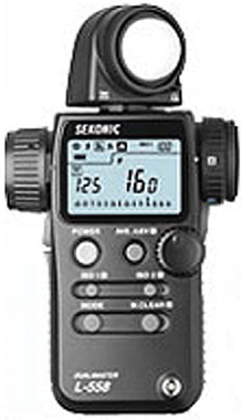
Figure 2.1: Digital spot meter.
I have run into this problem several times at concerts. Modern professional cameras have built-in spot meters (as do higher-end 35 mm and digital still cameras). Rather than taking a reflected reading at the wide angle setting, zoom into a close-up and take the reading. Some cameras require you to press a button labeled “spot meter” to achieve this. This is the only accurate way to obtain the correct exposure.
This is one of the few, extreme instances where I will not use a light meter and rely only on the camera’s internal metering system. It might prove difficult jumping up on the stage and holding a meter in front of the talent. I trust the camera for the most part, but nothing beats taking a reading at the source.
But why use a light meter at all if this form of metering is the same as the camera’s auto iris system and the WFM, which gives you very precise and accurate measurements on any section of the scene? The reason is that it is far more portable than a camera and WFM, and will permit you to light a scene without having to set up expensive video gear and pay a technical crew to stand by while you do your thing. Final decisions about exposure can be made once the camera system is up and running. At that time, you can use the camera and WFM to give you absolute assurance of the end results and to make critical decisions about the final look of a scene before rolling tape.
Incident Light Meters
Incident light meters are used by standing near the subject and aiming the meter’s light-sensitive cell toward the camera (see Figure 2.2). The cell may be covered with a hemisphere or a flat disk of some translucent material. The purpose of this translucent material is to filter out certain wave-lengths in the spectrum that could cause the cell to give incorrect readings. Just as the television camera must be aimed at a standard white card during white balance (see Chapter 1) to produce an accurate color signal, light meters are calibrated against a standard at the time of their manufacture.

Figure 2.2: Digital incident meter model auto meter VF.
They are calibrated to express accurate exposure readings when the light being measured is reflected from the surface of an 18% gray card. The dome or disk, known as a diffuser, converts the incoming light to the 18% gray card standard. If the diffuser were not in place, the light would shine directly on the cell and result in a nonstandard reading.
The hemisphere, or dome diffuser, allows you to measure light from as great an angle as 300° so you can measure all the lights focused on a subject.
The flat disk diffuser has a narrower angle of acceptance, usually about 50°. This allows you to measure the output of a specific instrument that is aimed at a subject lit by multiple instruments.
As you take your readings, be sure to aim the disk or dome toward the camera. Especially in the case of the domed meter, do not block any of the light that would normally fall on the subject in the position you are metering. The domed meter is particularly helpful when you are trying to set and focus individual instruments used to light an actor’s blocking. (Blocking is the path that actors are asked by the director to take when moving from point to point on the set.) It is important that you know where actors will be moving during the shot before you begin your lighting setup. Face the cell of the meter toward the camera and walk through the blocking to see the combined effect of all the instruments. (Many meters allow you to swivel the cell portion of the meter so you can see the reading from the back side of the cell while it is facing away from you toward the light).
You can let the meter guide you in your instructions to the grip (see Chapter 13 for an explanation of a grip’s role) in terms of the placement and focus of each unit. Lighting intensity can be consistently maintained throughout the blocking pattern if that is your intent, or you may wish to create areas of light and shadow. Walking this path lets you determine hot spots or dark areas on the set.
Placing the dome on the meter is helpful when you are taking readings to determine the exposure ratio of the set so that you can establish and maintain lighting continuity from shot to shot. If you walk to the foreground of the shot and take a reading, you can adjust the light to your predetermined level. Then you can move to the background area of the set and adjust the light so that you can maintain your predetermined ratio for that scene. We will discuss ratios and continuity in the next section of this text.
Videographers, unlike filmmakers, have other tools available to help them determine what the exact results of their efforts will be. I still use the same Sekonic Light Meter (see Figure 2.3) I purchased in college. Although it is old, it is still used by many professionals because it is a trusted analog meter that is both reflective and incident. This versatile instrument is used on every one of my shoots—film or video. Unlike most digital meters that display an exact f-stop, an analog meter makes you do the math to determine the correct stop—but it never needs a battery, like a digital meter.

Now we will discuss a second instrument common to video as well as still and motion photography.
Color Temperature Meters
Just as the intensity of light can be measured with a light meter, the color spectrum of light can also be quantified through use of a color temperature meter. One of the easiest meters to use for this purpose is the Minolta Color Meter III F. Its relatively high cost may be a valid reason for not having one of your own in your gadget bag, but there clearly are times when one should be rented for site surveys and actual shoots where you will be confronted with light sources operating at a variety of color temperatures. As indicated in Chapter 1, it is important to know the relative amounts of red, blue, and green light in the various sources that illuminate your scene.
The color temperature meter is used in much the same way as an incident light meter. The meter’s diffusion disk is aimed toward the source in question, and a built-in microcomputer memorizes several important factors about the light source. When you push the button marked “K,” the actual color temperature is digitally displayed in degrees Kelvin in the meter’s readout window.
When you push the button marked “CC,” the meter displays the color compensation index in a plus or minus figure. A reading of +3, for example, would indicate the need to filter a cool white fluorescent source with a ¼ Minusgreen filter to balance with a 5600°K daylight setting on your video camera. The correct filter to use for a given reading is indicated on a chart that is printed on the back of the meter. Although the chart is calibrated for film rather than video, a free Cinegel overlay that correlates the values displayed by the meter with Rosco’s video filtration media can be obtained from Rosco. This overlay is the same size as the chart on the back of the meter and can be peeled from its backing and stuck over Minolta’s chart.
Often, when a specific mood is desired, your color temperature could swing in a different direction than the norm. In a period film I shot about the early 1930s, I wanted all of the interior scenes to be warm and inviting—or in other words, an orange cast. By balancing to tungsten with a color temperature meter and then dimming the lights to 70%, I achieved the orange glow I was after. Although I could not determine this with my eye, by using the color temperature meter I saw that my light level would be orange. The result can be seen in Figure 2.4.
If you push a button marked “LB” on this meter, you will get a reading indicating the correct light-balancing index for the source light. For example, a reading of—131 would correlate to the need for use of Tough Blue 50 to boost a 3200°K lamp to match existing daylight sources according to the Rosco overlay mentioned earlier. The letters “CC” or “LB” will appear in the window along with the index number so there is no confusion regarding which area of the conversion chart you should refer to.
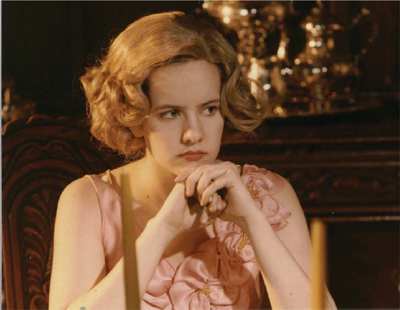
Figure 2.4: Warm glow in a 1930’s period film.
Knowing exactly which conversion filter materials to use in order to color correct for various mixed color temperature sources can save a great deal of time and money when you are faced with difficult lighting situations. Earlier color temperature meters were more difficult to use and designed in such a way that an error in reading the analog displays or interpreting charts was likely to contribute to some problems in selecting the correct filter material. The digital meter, combined with recent developments in filter material, makes it possible for good color correction to be made on location in seemingly impossible situations.
Besides the fact that it’s costly, some won’t use a color temperature meter because they believe the video camera will sort it all out. Most cameras will do an excellent job of this, but film cameras must still rely on the meter or the exposed film must be color corrected (either at the lab or in post production). It may be worth your while to rent a color temperature meter and take readings on your set. Sometimes these subtleties will improve your video with correction filters.
Additional Tools
Videographers have three tools unavailable to filmmakers which assist in achieving proper exposure and color balance: (1) the color picture monitor, (2) WFM, and (3) vectorscope. Used properly, these tools can guarantee results. They may also be responsible for the failure of some people in video to really learn their craft.
There is a tendency among some video people to think the camera’s auto white circuits will take care of problems involving sources with mixed color temperatures, that the auto iris will take care of exposure, and the zoom lens will permit convenient camera location to get the shot quickly. What more could you want? All cameras now focus automatically.
Accomplished film people would laugh at such thinking. They will have specific goals in mind when a scene is shot and be concerned about such things as depth of field, contrast ratios, exposure ratios, film stock, filter packs, lens focal length, camera angle, etc.—things that some video people do not consider or even know about. Film people have been in the business of exposing life to a recording medium for a great deal longer than video people have, and they have learned their craft well.
There should be no arguments between practitioners of the two media. They share common problems and can use common solutions. Each medium has its own unique advantages. Perhaps if the motion picture industry had grown up with all the automatic tools commonly available to today’s video crews, they too would have become as lazy as some members of the video community.
Besides having access to the light meter and color temperature meter used by film crews, video lighting directors have the color picture monitor, the WFM, and the vectorscope to guide them in determining proper exposure and achieving a specific look.
The purpose of discussing these technical aspects is not to make you a technician. It is intended to give you an understanding of how these tools can assist you to consistently obtain the look you want. It will also prevent you from being bullied by the technician whose solution to all problems is to demand more light. You should know what the system can and cannot do. Generally speaking, if your color monitor is properly calibrated, what you see is what you will get. There may be problems in the nonvideo areas of the signal (such as sync and blanking) that require technical attention, and the WFM and vectorscope will assist the technician in discovering and correcting them.
Color Monitor Setup Procedures
The WFM will provide you with the greatest amount of technical information about your setup, but a properly adjusted color monitor is your best friend when you are making decisions about the aesthetic aspects of the picture. Most of the new consumer analog and digital cameras offer a color viewfinder or pull-out color monitor. These monitors are not the same and should not replace a calibrated color monitor because it is nearly impossible to adjust these LCD color viewfinders correctly (most do not even have adjustments). Only the lower-end digital, consumer-grade analog and digital-video formatted (DV) cameras have color viewfinders. The higher “pro” models still use black-and-white because it is easier to focus.
With a properly adjusted color monitor you can ask: Is the depth of field what you want? Are the exposure ratios correct? Does the lighting lead the viewer’s eye to the center of interest? Is the mood of the scene correct? Can you see the detail you are looking for? Is the picture noisy in the dark areas or overexposed in the highlights? These last two aspects can also be determined by using the WFM.
You need an accurate, calibrated visual indication of the camera’s signal. You should invest in a high-quality monitor because cheap color sets will not render colors accurately and are, in fact, designed to mask noise and other factors that are sure to show up on good monitors in the post-production suite later on.
When working at a TV station shooting commercials, we always carried a 3-inch, portable color monitor to make sure our Betacam SP footage looked alright. The camera didn’t have color playback, so we relied on checking the color signal from the camera’s video output. Everything always looked great on that monitor because the image was so small, the resolution so sharp, and most problems were masked. When we got back to the editing suite, the footage never quite looked so great.
Once the monitor has been properly set up using the correct test signals, it should be left alone. If the scene does not look right to you after monitor setup is complete, change the lighting, the f-stop, or some other aspect of the camera setup until you achieve the look you want. Diddling with the monitor will do nothing to correct the problem, and it will make any later evaluations you make with that monitor invalid.
I have been on location when the client looked at the monitor and said that they did not like the look of the shot. They wanted more detail in the dark areas. Instead of changing the lighting or some aspect of the camera setup, they adjusted the monitor until they saw what they wanted! The controls on the monitor should not be used to “improve” the picture.
Using Test Signals
As mentioned in Chapter 1, the camera produces a proper color signal based on its ability to reproduce white. White is the reference used in the auto white balance procedure. A similar situation holds true with a color monitor. The technician should begin the setup by making sure the set is properly converged so the red, blue, and green guns are not misaligned. Once that is accomplished, continue the setup procedure using a monochrome or black-and-white signal. A gray scale generated by a signal generator is preferred, but if you do not have a test signal generator, you can play back a videotape of a black-and-white movie or a gray scale produced by a signal generator. If you use a black-and-white movie, you should select a scene that contains black areas, gray areas, and white areas. If the monitor introduces any color or tint into the picture from your monochrome signal, adjust the screen and gain controls of the monitor.
You may be tempted to shoot the chip chart with your color camera to perform this test, but this would not provide a true black-and-white signal, and if the resulting image on the monitor showed signs of color anywhere, you could not be certain if the problem was the result of improper monitor adjustment or incorrect camera encoder setup.
Unfortunately, there is no scientific method of establishing precise monitor setup in the field. Even though there is still room for error in the first method described here, using test signals will provide far better results than will any random adjustments based on subjective viewing of regular program material. The second method, employing SMPTE (Society of Motion Picture and Television Engineers) color bars, is extremely easy and accurate. This method is described below.
Color Bars
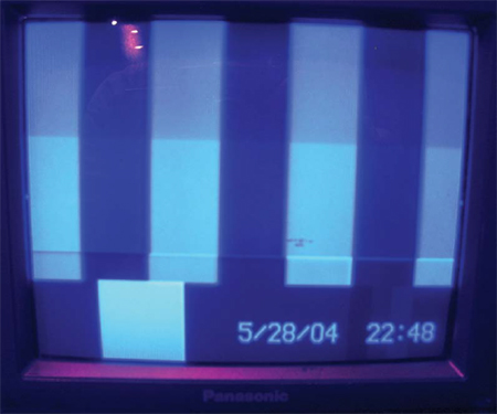
This next step in the setup process is subject to error caused by your visual perception, but it should be reasonably accurate. Using the monochrome signal, adjust the monitor’s brightness control for proper levels of the black areas of the picture. The details in those areas should be readily apparent. If the monitor is equipped with cross-pulse capabilities, activate the cross-pulse signal and adjust the brightness so that the blackest picture area is just slightly brighter than the blanking area (see Figure 2.5). This is one adjustment that will change from location to location, depending on the ambient light falling on the face of the screen. Naturally, you should try to position the monitor so that neither bright studio lights nor the sun will wash out the picture.
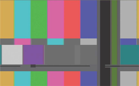
Figure 2.5: Image from a cross pulse monitor and blanking information.
Before continuing, a word about color bars. There are three basic types of color bars generated by cameras and test equipment. The first standardized bars conformed to the Electronic Industries Association (EIA) standards of 1967. Technically, they are RS-189 bars, commonly known as “full-field bars,” illustrated in Figure 2.6. These were revised in 1976 to become RS-189-A bars, commonly known as “split-field bars” (see Figure 2.7). Though both versions are intended for use in setting up color monitors, among other things, they are not very well suited to the task. They serve other test functions far more efficiently than providing a standard for color monitor setup. During the monitor setup procedure just described, it was assumed that a version of EIA bars was all that you had available.
In 1978, an SMPTE committee report recognized the shortcomings of EIA color bars with respect to monitor setup and proposed the color bars shown in Figure 2.8. At last there was some science to an otherwise educated-guess procedure for monitor setup. As with many good ideas, this one about an improved form of color bar was not widely accepted until recently. I cannot imagine why.
In the field, color bars will be generated by the video camera. All professional and most semi-professional cameras have this feature. Sony’s DV and DVCAM cameras, as well as ½-inch and above CCDs generate EIA full-field color bars.


Figure 2.7: EIA split-field color bars (RS-189-A).

A simple and accurate brightness setting can be accomplished using the SMPTE color bars. Brightness is set with the aid of the three vertical black mini-bars that are located in the lower right-hand corner below the main red bar of the signal. The three black bars are very close in value specifically to provide a reliable key to brightness adjustment.
The left bar of the trio is just a bit blacker than black. The small center bar represents true black. The right bar is just slightly brighter than true black. The idea is to adjust the brightness control of the monitor so that the bar on the left cannot be seen. If it is visible, the brightness control setting is too high. If the bar on the right cannot be seen, the brightness control setting is too dark and should be brought up just enough so the right bar is visible. At the proper setting the blacker-than-black mini-bar and the center, true black bar will not be visible. Only the whiter-than-black bar should be visible. This simple, foolproof method of adjusting brightness is more accurate than the cross-pulse method previously mentioned and requires less time, fewer test signals and assures far greater accuracy.
Adjust the contrast control for proper levels in the white picture areas. Details should be visible in the white areas, and the brightest white produced by the monitor should not be so bright that it causes eye strain. Like the adjustment of the brightness control, the contrast adjustment will change from location to location depending on ambient light conditions.
Once you have adjusted the brightness and contrast controls, you are ready to start making adjustments that affect color reproduction. If you use the older EIA bars, change your signal source from a monochrome tape or signal generator to the color bars from your camera or a signal generator. Obviously, the camera is the least complicated source for this signal, especially on single-camera shoots.
The two controls involved in color adjustment are the color and hue, sometimes called tint.
The color control adjusts the saturation or amount of color present. It should be adjusted so that the color bars appear normal and are not oversaturated. When colors are oversaturated, they begin to “bloom” or “bleed” into the colors that surround them.
Usually when you are looking at full or split-field color bars, the red bar is the first to bloom into the magenta bar on its left and the blue bar on the right when the color control is set too high.
The hue or tint control is perhaps the most subjective adjustment of all. The idea is to adjust the hue so that the colors appear natural—not too red and not too green. I prefer to make the adjustment watching the red and magenta color bars. When the magenta is correct, not too red and not too blue, I am satisfied with the setup. Some like to make this judgment watching the cyan bar. Your preference about which bar to use as a reference for hue setup should be based on your own sensitivity to color.
Using EIA bars, it is a bit tricky to adjust the color (saturation) and tint (hue) properly. If your monitor has a “blue only” setup switch, you should activate the setup switch so that only the blue gun displays the color bar signal. Rotate the color control so that the outer two blue bars are of the same brightness. The hue control should be adjusted so the inner two bars of blue are of equal brightness. When all four bars are of equal brightness, the monitor is properly set (see Figure 2.9).
One of the most difficult judgments to make is determining when the outer two bars are equally bright when adjusting the color control. Their distance from one another is the biggest factor in making your judgment. Since the inner bars are closer together, the hue adjustment is a bit easier. No matter how good a job you think you have done using EIA bars, you will find that no two people seem to come up with the same settings using the same bars on the same monitor. A better mousetrap was needed.
Here is the SMPTE solution. That narrow row of seemingly useless colors below the regular color bar display of the SMPTE signal is an ingenious blend of tints that can be used in conjunction with a blue gun only setup switch to provide completely accurate color and tint adjustment. It is foolproof.
The idea is to display the SMPTE bars using the blue gun only and adjust the color and tint controls so that the upper portion of each bar is the same brightness as the smaller section at its base. This is a very easy judgment to make since the two sections are always contiguous and the slightest discrepancy in brightness is easily discerned. When each of the seven segmented bars looks the same from top to bottom, you have accurate adjustment of the color and tint controls.
Once the monitor is adjusted, keep your fingers off the monitor controls. If the set is lit and you do not feel there is enough detail in the black areas, add more light. Do not mess with the brightness control of your monitor. If white areas of the picture are losing detail, reduce the light falling on them or, in the case of windows with natural sunlight coming through, increase the neutral density (ND) filtration. If you have no additional ND filter material available, use the color monitor and WFM as guides to stop down until you get the detail you are seeking. Then you will have to add more base light to the scene to keep the black areas from compressing to the point where excessive detail is lost in the dark areas.
If the picture looks good on the monitor, and by good I mean that it conveys the mood or atmosphere you want, do not let the engineer bully you into adding more light because 100 IEEE units are not present somewhere on the WFM. Not every scene must have a full range of brightness from black to peak white. The zebras in a professional camera are usually adjusted at 100 IEEE. When you notice the zebra’s “little lines” in the viewfinder, you have exceeded 100 in those areas.
Waveform Monitor
The WFM has two basic functions. It measures the amplitude and the timing of video signals. For a lighting director, the only concern is with the measurement of the amplitude of the signal. The amplitude has a direct relationship to the brightness of any area of the picture. For this reason, you can use it as both a spot meter and a reflective meter.
You should be familiar with two technical matters associated with the WFM. The first is its unit of measurement. A light meter is calibrated in foot-candles. The WFM is calibrated in IEEE units.
The IEEE scale is etched on the left side of the face of the WFM as shown in Figure 2.10. Your concern is with that portion of the signal between the 7.5 IEEE unit mark, which represents TV black (referred to as “setup”), and the 100 IEEE marking, which represents TV white. The portion of the signal below the 7.5 unit level is the responsibility of the engineer. The technical director chose to mark specific levels with yellow arrows for his own comfort level.
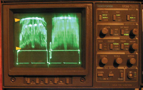
Figure 2.10: Waveform monitor.
The WFM will give you exact information about the intensity of all areas of the scene and the individual elements in a given area. You can meter each shot with the WFM and make a note of the brightness of various elements. You can view the brightness of all elements of the shot, or you can zero in on specific areas in close-up. Note the level of specific areas, such as the background, in your first setup for a series of shots and then check ratios during post-production. Be especially observant of peak white and black areas so they do not bounce around from shot to shot in a given series.
Sections of the WFM display may be viewed in normal or expanded detail to give you precise information about any specific area of the picture. In this way it functions somewhat like a spot meter, but it provides far more accurate information. While the WFM is actually the responsibility of technicians, you should use it to fine-tune your efforts. In general, keep flesh tones from 40 to 50 IEEE units. Highlights should be at about 85 units with burnouts (such as practical lights on set, or a window) at 100 units. Ask your engineer to set the clips in your camera at 100 units rather than 110 IEEE units as some do.
Zebras
All prosumer and professional three-chip cameras have zebras. As mentioned earlier, these tiny lines appear when your video luminance exceeds a predetermined level—appearing like the stripes on a zebra (see Figure 2.11). Cameras usually have three settings for zebras: 70%, 100%, and off.

Figure 2.11: Zebra stripes on a DVCAM monitor.
I usually set my zebras at the 70% setting so I am aware that the video brightness is not yet at 100%, but it is getting close. Others set theirs at 100% and then back off the iris when the stripes appear. This setting doesn’t do away with the need of a WFM, but on location, it is helpful to have a pseudo-WFM built into the camera. The set-up level is also adjustable on most cameras. Those who prefer their blacks to be very dark and rich, set their set-up (black level) at 0 IEEE rather than the normal 7.5 IEEE. Check with your end user to see if 0 IEEE would be a problem (some TV facilities will not accept digital tapes at 0 IEEE).
The second technical matter you should be aware of is the filter switch. Be sure the WFM is not in the flat response mode when you take your readings. In the flat response mode, it will display the color (chrominance) information as well as the brightness (luminance) information. Your only concern should be with brightness or luminance information. The filter button has two positions, the flat pass or the L pass (low pass). Use the L pass position for your readings; it will remove the color information.
The WFM has a Vertical Rate Display mode and a Horizontal Rate Display mode. In the vertical mode (see Figure 2.10) it displays each complete field of the television picture. The left half of the display is Field One (Lines 1, 3, 5, and so on). On the right is Field Two (Lines 2, 4, 6 and so on). This setting allows you to evaluate the entire picture. If you want to check the brightness of a specific small area, you can zoom to a close-up and observe the WF display.
In the Horizontal Rate Display mode, the timing of various elements of the signal can be checked, but this mode is for the technician’s use only.
WFMs are also built into most nonlinear editing systems. Adobe Premiere, Avid, and Final Cut Pro are some the systems that incorporate the WFM next to the display window. When used on a laptop, the signal can be sent directly to the NLE system via a FireWire (IEEE 1394) and displayed.
Vectorscope
The vectorscope provides information about the two chrominance aspects of color, hue and saturation. Its circular display is divided into 360 1° increments (see Figure 2.12). The six primary and secondary colors are represented by boxes etched at various positions within the circle on the faceplate. The saturation of the color can be determined by the length of its trace from the center of the display.
As a lighting director you can use the vectorscope to help you maintain color consistency of a given element in the scene from one shot to the next.
A client’s logo or product color is sure to be a very important element in any shoot, and there is an easy way to make sure that the last shot looks as good as the first one the client raved about.

A surefire trick that I employ is to light the first shot to the client’s satisfaction regarding product color rendition. Say the product is a set of bright red shock absorbers. Once the product’s hue and saturation have been established, you can take a grease pencil and mark the trace that represents the product on the faceplate of the vectorscope. If you are unable to determine which portion of the vectorscope’s display represents the product in question, zoom in to a close-up and fill the screen with the product. Now the product’s trace on the vectorscope will be obvious. Follow that trace on the scope as the camera operator zooms out to the shot called for by the director. With the iris set for that shot, mark the trace with a grease pencil on the faceplate of the vectorscope or on a piece of acetate you have placed over the faceplate. Now you will know the exact color of the product and the saturation of that color. In the case of the red shock absorber, the trace will be near 260° out a specific distance from the center of the display. The position of the trace in degrees indicates the color, and the length of the trace from the center tells you what the saturation is.
When you light the product shot that will precede or follow your first setup, you can check for matching hue and saturation on the vectorscope by comparing your grease pencil mark to the current trace of the product on the scope. Adjustments may be required to produce a similar trace on the scope, but once the product trace of the current shot matches the earlier marking, you know the shots will cut together in the edit suite.
The technician will use the vectorscope for other purposes, but this is one way you can use the tool to assist with your job function. Again, it’s another assurance unavailable to the filmmaker that you have at your fingertips.
Digital Waveform Monitor/Vectorscope
The video signal can be broken down into three types: composite, component, and digital. Composite is the type of signal we just discussed. The signal is sent to the monitor or WFM combo through one cable (usually a BNC). The next step up in resolution and quality is component. This signal reaches the monitor through three cables (Y, B-Y, R-Y). The image is sharper because one cable does not have to carry all of the video information (Figure 2.13). Progressive scan DVD players use these three cables (red, blue, and green) to display sharper images than the S-VHS cable allows.
The third type of signal is digital. The digital signal is input with a serial multipin cable or a FireWire (IEEE-1394). Some models combine the WFM and vectorscope into one unit. Both pieces are needed on the set, so weight, space and cost savings are realized.
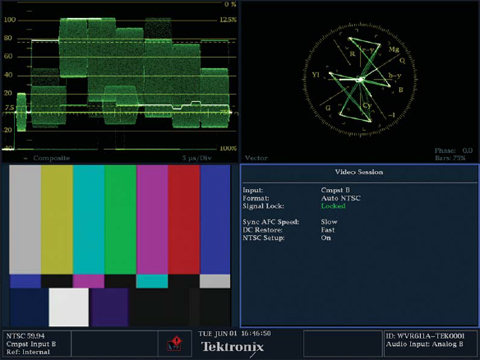
Figure 2.13: Analog component/composite waveform monitor/vectorscope (Photo courtesy of Leader Co.).
If you are shooting in the digital realm, the color bar signal to the WFM and vectorscope will look different on the display (Figure 2.14).
The adjustments and levels are still the same, just the appearance has changed. You now have control over more of the video signal. These adjustments are best left to the engineer.