Nearly all essential models require event responses to communicate with one another via stored data. The corresponding implementation models thus must include a description of the stored data implementation. The stored data that must be available to the tasks within a single processor is shown by the portion of the entity-relationship diagram (or the equivalent set of transformation schema stores) allocated to that processor and by the associated data specifications. Data that is shared among a set of processors is thought of as belonging to each of the processors. In this chapter, we shall focus on modeling the implementation of and access to stored data shared among tasks within a processor. We shall also discuss modeling the co-ordination required when stored data is duplicated among processors.
Widespread and uncontrolled sharing of data between tasks is generally, and quite correctly, regarded as poor design practice because it violates the general criterion of organizing for maximum implementation independence. Nevertheless, data must be shared to the extent required by the essential model; the problem is to reduce the dangers implicit in this sharing to a minimum.
This problem has been faced before in commercial systems, and it has led to the development of a specialized technology — database management systems, databases, inquiry languages and the like. However the volume of data in such systems is often larger than in typical real-time systems and the access time requirements are often not as stringent. Data management technology has therefore become associated with the use of disk storage and with (relatively) slow access times, and consequently many reject the use of the technology in real-time systems. We feel that this is an error for several reasons. First, many real-time systems do in fact store relatively large quantities of data that can be accessed within the time constraints of disk technology. Second, the concepts of data management technology do not limit themselves to disk storage implementations. Third, these ideas, even if they can only be applied as restricted by real-time timing constraints, still provide significant benefits as guidelines to stored data organization.
Let us begin by defining some terms. A database is a collection of shared stored data items. It is important to distinguish the data that makes up the database from any software that manipulates the data, and from the organization or description of the data. A shared common block between several FORTRAN programs matches our definition of a database. A data description language is a (usually textual) means for describing the organization of the data that exists or will exist in a database. The term data schema is often used for the resulting description; however, we have reserved this term for the entity-relationship diagram and its supporting specifics. We draw a distinction between our use of the terms data schema and data description by restricting the latter term to a description of the data that is processed by some specific collection of database software. (To the best of our knowledge there is no currently available software that can use the data schema as we use the term to define the organization of a physical database). Data access methods are mechanisms that use the data description of a database to access data in a database. These terms are defined in more detail in [1].
This restricted set of definitions is sufficient to enable us to demonstrate the useful data management concepts. In a real-time system stored data exists and is shared (a database); the static organization of data and its use by tasks is defined (data description languages); and data is referred to and manipulated through knowledge of its organization (via data access methods). Typically, the data description language and data access methods are implemented via a programming language. In FORTRAN, for example, data is defined via common block definitions and accessed by name from the programming language.
The next two sections examine design criteria that motivate the development and use of data management technology.
Consider a commonly found implementation of stored data: there is a single globally accessible shared data area, whose organization is defined by the data definition facilities of the chosen programming language; every task in the system that shares data is compiled with the definition of the entire shared area, and thus has access to all the data at any time. There are several problems in this scheme. First, no protection is provided for any of the data elements; if a data element exhibits an incorrect value, there are no clues as to which task modified the element since all tasks have access. Second, any change in the structure of the stored data will lead to recompilation of all tasks in the system. Since all tasks assume the same structure for the data, then if any one task changes its view, all tasks must follow suit. Typically, this is time-consuming and error-prone, which leads many programmers into taking short cuts, such as finding an unallocated area of memory and making private agreements on the use of this area between the tasks that share it. Third, data access mechanisms are specific to each task, which leads to duplication of effort and further dependence on the present data structure. Clearly, this scheme has significant disadvantages; however, it is fast. References to data locations can be resolved at compilation time so that data elements can be accessed simply by a reference to an address.
In its attempt to overcome these problems, a key objective of data management technology is the achievement of data independence; that is, each task should be unaware of the storage structure and access mechanism of the data accessed. If data independence is achieved, stored data can be reorganized with no impact on the code of each task. Data management technology achieves data independence by interposing one or more layers of system software between the application task and access to the data itself. In this way, a call is made to a system software task which then uses a data description to access the data item. These “additional” layers of code may introduce inefficiencies into the implementation, which can cause problems in a real-time system.
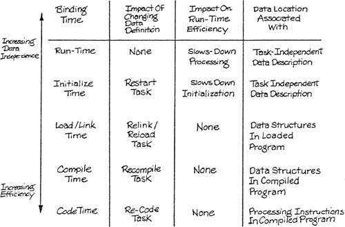
The efficiency and independence objectives are clearly in conflict. The two objectives can be studied together by introducing the concept of binding [2]. In compiler theory, a name is said to be bound to a location when the location is associated with the name. (The term is also used to refer to the association of a name to an identifier, and the association of a value to a name.) In the case of a single globally shared data area whose definition is compiled into each process, the names are bound to locations at compile time (or if the location of the shared area is not fixed, at link/load time). On the other hand, the use of a procedure to access a data item will delay the binding until run time. It is the execution of the binding at run-time that causes the use of data management technology to be less efficient, yet more independent.
Table 7.1 summarizes the independence and efficiency characteristics of different binding times.
There are two faces to data organization implementation: the view that is presented to the designer and programmer, and the actual physical organization of the data on the chosen storage media. The designer and the programmer will want to perform operations on data structures according to an external view of how the data is grouped and organized; this can be separated from the internal data structure chosen for the data. It is the business of any data management software to provide mechanisms to manipulate the external data structure which can then be translated into operations on the internal data structure.
There are three basic approaches to organizing data structures [3] each of which applies to both the external and internal models. Often, it is natural to use the same approach for both models; though it is by no means necessary. These approaches are:
the relational approach, in which the basic data structure is a table, or
the hierarchical approach, in which data is stored in hierarchical trees and there is only one path to a given data category, or
the network (or CODASYL) approach, in which data is stored in a network of nodes and there may be several paths to a given data category.
The approach chosen will affect the operations that can be carried out on the data structures. The remainder of this section describes the three external views of data. The internal structure chosen may match exactly, or may be chosen to be different for efficiency reasons.
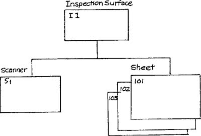
Consider the entity-relationship diagram shown in Figure 7.1, which is derived from the Defect Inspection System (Appendix D). The relational approach would view the data organization as a set of tables, as shown in Figure 7.2.
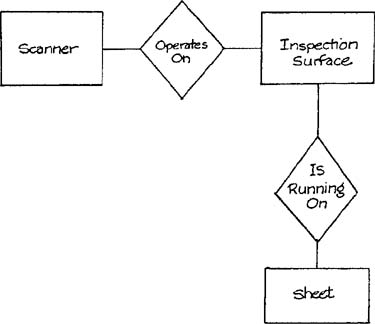
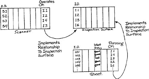
In this case, the relationships are implemented by data elements that refer to other tables. (For example, to find out which inspection surface sheet 105 is running on, we examine an additional data element for the sheet that specifies the identifier of the inspection surface.)
Contrast this organization to a hierarchical storage model as shown in Figure 7.3. In this case, the relationships are implemented by pointers rather than as data. If the system were to need to mark all sheets scanned by a scanner as BAD in response to a fault in the scanner, it is necessary to move up the tree to find the associated inspection surface, then down the tree to find all the sheets running on that surface.
The network approach, however, could obviate the need for this step by choosing to have two parents (or owners) for the sheets as shown in Figure 7.4. This design might be necessary if scanners failed frequently and the time taken to navigate the structure was too long.
Once an approach is chosen, and the appropriate manipulation procedures are either written or purchased, the total volume of code can be significantly reduced. Returning for a moment to Figure 7.2 (the relational model), if the task is to set all occurrences of a sheet that has been misscanned by a failed scanner, then the code is simply:
Find the inspection surface for the failed scanner
Find all the sheets that are running on that inspection surface
Set the defect status for all these sheets to BAD
Please note that find and set are simply general queries on the data that can be implemented just once and used in many contexts. We shall detail similar operations in subsequent sections.
A unified external view of data has several advantages. First, designers and programmers need have only a single standardized set of data manipulation operations and data structures to understand, rather than several idiosyncratic ones. Second, data can be reorganized without affecting code as a result of data independence. Third, data may be reallocated between primary and secondary memory transparently [4].
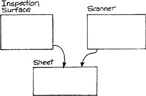
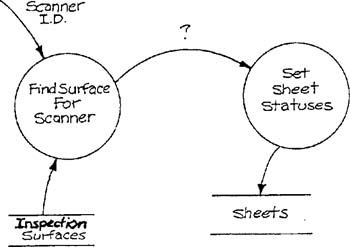
We shall discuss in this section a relational organization of data. We have chosen this approach for the external view of data for the following reasons. First, the underlying data structure is extremely simple (tables). This allows the designer to construct procedures that assume a single, simple data structure. Second, connections among operations on data are independent of the implementation. For example, consider two tasks, one which finds which inspection surface a scanner is running, and another which sets the defect statuses for all the sheets on an inspection surface, as shown in Figure 7.5. In a relational model, the data flow between the two is the identifier of the inspection surface. In a hierarchical model such as the one in Figure 7.3, the result of the equivalent task that finds the inspection surface would have as output a pointer to the inspection surface. The task that changes the defect status would have to be designed to accept the pointer; this would then make the task useless if the pointer mechanism were to be modified. Similar problems appear if a network approach is utilized. Third, embedded real-time systems tend to have complex environments which are liable to be expanded, modified, or reconfigured [5]. This places a burden on the designer to construct a system that can withstand frequent modifications to the data structures and the code that operates on them. Since the relational approach represents connections between tables in data, the connections are bound at run-time — a more general approach than the alternatives.
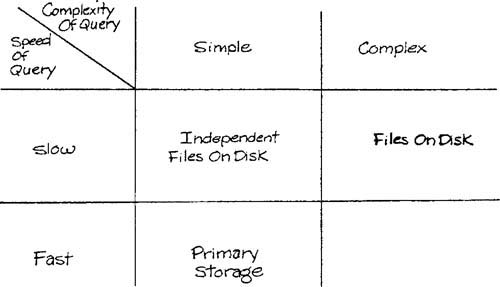
Relational databases have a reputation for being slow, even in a commercial system environment. The generality of the approach and the late binding of data to implement relationships tend to justify this reputation. However, as we stated earlier, it is not necessary to use the same storage approach internally. For example, a relational interface could be constructed that, for certain queries, operates on data in memory stored as relational tables, but translates other queries to a network database on disk. This scheme would then present a common unified view of data to designers and programmers that is independent of the internal organization. Data may be allocated to memory or to a disk based on, first, speed of access, and, second, complexity of required queries. (The complexity of a query will have an impact on speed.) The allocation strategy is summarized in Table 7.2.
In the next section, we address the external operations that manipulate stored data in the relational approach.
Stored data is manipulated by tasks: data is retrieved, computations are carried out, and data is stored. To preserve data independence, the retrieval and storage activities should be independent of the precise data items that are being accessed. Again, data management technology can provide us with some guidelines.
The two basic operations we require are SELECT, which chooses a set of rows from a table according to some criteria, and PROJECT, which chooses a set of columns from a table. For this discussion, we’ll assume that the results of the operations are table descriptors; data can then be accessed by GET and PUT operations. Referring to Figures 7.1 and 7.2, the code to flag all sheets checked by a faulty scanner as BAD is:
* find the scanner scanner-table ← OPEN (SCANNER)broken-scanner-table ← SELECT (scanner-table, SCANNER-ID = input-scanner-id)* find which inspection surface it's onoperating-on ← PROJECT (broken-scanner-table, OPERATES-ON)inspection-surface ← GET (operating-on)* find the sheets in the inspection surfacesheet-table ← OPEN (SHEET)bad-sheet-table ← SELECT (sheet-table, RUNNING-ON = inspection-surface)* identify the defect status columndefect-table ← PROJECT (bad-sheet-table, DEFECT-STATUS)* set the defect statusPUT (defect-table, "bad")
The upper case variable names are strings that are searched for at run-time in a data description; this allows for the data that represents each data element to be stored anywhere. The table descriptions simply identify the elements being accessed, and the shared data is passed to or from the task only by GET and PUT operations.
Many simplifying assumptions have been made: adds and deletes are not allowed during the operation of the task, operations are defined only for single tables, elimination of duplicate rows is not carried out, and we have not defined the organization of the workspace in the task. Nevertheless, we have achieved many of the advantages described in the previous sections.
A third relational operation, the JOIN, may also be made available. The join operation constructs a new table from rows in the input tables by matching from columns that have a common domain. The resulting table typically contains redundancy. In the general case, the join operation is a time-consuming process, and is therefore often inappropriate in a run-time system. However, if the resulting table is operated on frequently, it may be advantageous to perform the join offline and store the resulting table in primary storage. In this case, all tasks that operate on the table are less independent of the data structure than is desirable because they must account for the redundancy.
The data schema for each processor provides a basis for an allocation between primary and secondary memory. Each data element should be tagged appropriately as indicated by Table 7.2. We now focus only on elements allocated to primary memory.
Each object type becomes a table in which each data element is a column of the table, and each occurrence is a row. The physical representation of each data element should be defined, and the actual (or maximum) number of occurrences in the table should also be specified. This information constitutes a data description.
Relationships are also represented as tables. When the relationship between object-types is one-to-many, an additional column may be added to the object-type on the “many” side of the relationship that contains data that identifies a unique occurrence of the other object-type. When the relationship is one-to-one, the additional column may be added to either object-type. When the relationship is many-to-many, a new table should be constructed which contains references to unique occurrences of each participating object-type. The columns of the resulting table should contain elements that make up the identifiers of the appropriate object-types. Again, the characteristics of the columns and tables should be added to the data description.
The data description produced by the translation of the entity-relationship diagram into relational tables may serve as input to a preprocessor (a data description language translator) that allocates space in primary memory and builds tables that describe the allocation. These tables are then used by the data manipulation operations to find and access run-time data. [6]
In the next section, we shall describe how the data description may be used to speed access to stored data.
From the data description, the data description translator produces an allocation for the tables defined for the application. This allocation may contain absolute addresses or addresses relative to the base of the shared data area. The data manipulation operations described in Section 7.6 bind names within a task to these locations at run-time. In certain situations, this may be too slow to meet implementation constraints.
GET and PUT operations in time-critical tasks may be translated into direct accesses to memory by a preprocessor applied to code written in the language of choice, since the addresses referred to by name are known by the data description translator. This technique binds names to locations at preprocessing/compilation time, and will require recompilation of all such tasks if the data description changes. It also requires that tables may not be added or deleted. Nevertheless, many of the advantages of data independence are still accrued.
This technique can be carried further. If static data is operated on by SELECT and PROJECT operations, these operations may be executed on a copy of the static data at preprocessing time. The processing load is transferred away from run-time into the non-time-critical construction activities.
A less radical approach may be taken that still has the advantage of shifting processing load away from run-time computations. Resolution of names into addresses may be carried out by initialization tasks that compute pointers to the data to be operated on, and pass these pointers to run-time tasks.
In a multiprocessor environment, the stored data derived from the essential entity-relationship diagram will be fragmented across several processors, and some of the data will be duplicated as described in Chapter 3, Processor Modeling. The physical data schemas for each processor are annotated with references to the master version of each data element from which others are duplicated. However, the activity of duplicating the data elements has not yet been modeled. The issue at hand, therefore, is to decide when each data element must be copied from the application’s point of view. Please note that tasks to carry out the copying qualify as system software and can therefore be modeled using the techniques of system software modeling as described in Chapter 6.
Data items representing continuous variables that are updated by periodic tasks are candidates for periodic copying between processors. The interval chosen for the copying is dependent on the use the receiver makes of the data. For example, a task may monitor and control a particular device at very short intervals; an operator may also be interested in examining the data being used for the monitoring. It is most unlikely that an operator will wish to see this updated data as frequently as it changes, and a much more leisurely pace may be appropriate. It is therefore the receiver that determines the rate of any periodic update between processors.
Discrete data elements may also be copied periodically between processors. Each cycle, all the chosen data elements are copied regardless of whether they have been changed. This is a simple way of keeping data consistent between processors, so long as the data items are not internally inconsistent across any cycle. Discrete data elements may also be copied between processors only when the data element is changed. This may be implemented by the interposition of database management software between tasks that change data and the actual database so that changed data elements can be marked as needing to be copied, or by explicitly making a request to copy certain data elements. The task that carries out the copy may keep data that describes the destination task(s) of groups of data elements.
Variations and combinations of these techniques are also possible. For example, whole blocks of data might be marked to be copied even if only one element in the block has changed. Similarly, all discrete changes of data elements may be collected and transmitted periodically. The choice between these various techniques should be made on the basis of data consistency, permitted delays in modifying updated data in the destination processor, and the capacity of the transmission links as described in Section 5.3 of Chapter 5, Interface Modeling.
The techniques of data management technology are applicable in real-time systems. However, the costs, particularly the run-time efficiency costs and the benefits, must be carefully weighed. The later the binding time, the more likely the system is to be data independent and easy to modify, but it is likely to be less efficient.