Many embedded systems have suffered from inflexibility. Accommodating a change in user requirements, or re-implementation in a new hardware or software environment, requires such extensive changes in these systems that they must be rebuilt from scratch. A major cause of inflexibility is failure to separate the portions of a system that implement the application from the portions that provide the support environment. The inflexibility of many early real-time systems was inevitable because of the limitations of the available processor hardware; maintainability can take precedence over operational efficiency only when there is sufficient capacity available. However, we have argued in Chapter 1 of Volume 1 that there is a large class of systems for which processor capacity is sufficient. Thus the problem-dominated approach to systems development dictates the separation of systems support from the application.
In this chapter, we will provide guidelines for identifying and modeling the system support environment required for an application. The scope of this chapter includes utilities such as device handlers, intertask or interprocessor communication managers, interrupt handlers, task dispatching routines, and mathematical subroutines. Utilities that primarily deal with the management, storage, and retrieval of stored data within a system, such as data base managers, are the subject of the next chapter.
We define the semantic level as that combination of scope, boundary choices, and vocabulary that defines the modeler’s point of view of a system. Please refer to the informal discussions of the banking system in Chapter 1 of Volume 1, which provides some preliminary examples. Let’s return to the banking system and consider three tasks that might be included in an implementation:
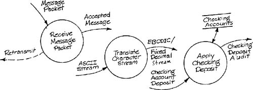
a task that receives a message packet sent over a data communications line, strips the parity bits, checks parity, and requests retransmission if necessary.
a task that translates an ASCII character stream by identifying field markers and changing alphanumeric fields to EBCDIC format and numeric fields to fixed decimal format.
a task that accepts a checking account deposit, checks it for legitimacy against a file of checking accounts, updates the file if the deposit is legitimate, and issues an audit report.
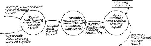
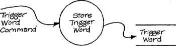
The three tasks are illustrated in Figure 6.1. Notice that the tasks are drawn in a disconnected fashion, although a banking transaction might well go through the three tasks in sequence. The problem is that the three tasks have different semantic levels, and thus have incompatible data flows. In order to connect the three tasks into a sequence, it is necessary to associate the semantic levels in some way. Figure 6.2 accomplishes this by mixing the semantic levels. The problem with this model is that it invites mixing application code and software support and pushes the system builder toward an inflexible design. Figure 6.3 provides another strategy for sequencing by defining all three tasks in a very abstract manner. Although the problem of mixed semantic levels has been avoided, all information about the primary semantic level (banking) has been lost.
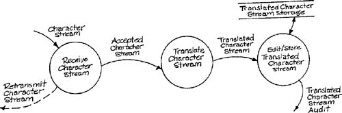
The problem illustrated by Figures 6.1, 6.2, and 6.3 occurs in a large number of implementation situations. To create a rigorous model of the implementation, it is necessary to describe the connection between the application tasks and the system utility tasks. However, a simple joining of models is not satisfactory for this purpose. Our solution is to build separate models for system utililties and to cross-reference them to the application model. The details of this solution will be laid out in the remaining sections of this chapter.
There are many cases when a formal model of a system utility is necessary for effective systems development. If a new utility must be built to support an application, a model is as important as in any other development situation. If an existing utility is reasonably complex, a model may be necessary to verify that the utility will interface satisfactorily to the application tasks. (If a model of a complex system utility doesn’t exist, one may have to be created after the fact; reading code is not a very satisfactory way to visualize a system’s operation.)
In most senses, a model of a system utility is no different from any other model. It can be built using the modeling tools and heuristics described in the present three volumes. In fact, a system utility built as an end in itself (say, as a product of a software house) is equivalent in all respects to an “application system.” A system utility built as an offshoot of another development project has two characteristic differences from other development models. First, it is developed with a semantic level that is “referred to” by another semantic level. Although details of the original application are not included in the utility model, the appropriateness of the utility model will be judged partially by how conveniently it supports the application. Second, the semantic level of the utility model may be difficult to pin down because of its remoteness from the original application.
Let’s explore a system utility that will be needed to implement the SILLY system (Appendix C in Volume 2) — a keyboard handler. The utility could be implemented as a hard-wired digital circuit. However, for now we’ll just examine the essential model. The keyboard mechanism linked to the utility consists of a two-dimensional grid of read and write lines like the one illustrated by Figure 1.4 of Chapter 1 in Volume 2, Essential Modeling Heuristics. The context schema for the utility is shown in Figure 6.4. Note that there are no discrete input flows. The system is inherently time-driven and is based on four time intervals. The shortest time interval reflects the time required for the read line values to settle after the write line has been changed. The intermediate time intervals control the delay between the sending of the Key Available event flow and the actual key data, and the cycling of activation of the write lines. The longer interval drives the interpretation of accumulated line values (debouncing) to determine if an unambiguous hit has occurred. The external events for the system are Time to Cycle Write Lines, Time to Store Read Lines, Time to Check for Key Hit, and Time to Transmit.
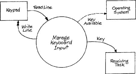
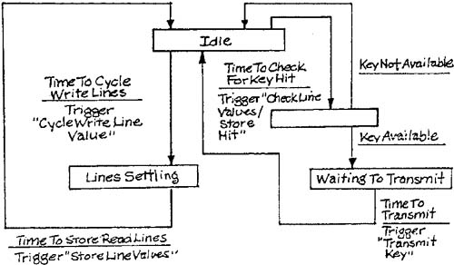
Figure 6.5 shows the transformation schema for the keyboard utility, and Figure 6.6 shows the state transition for the control transformation of Figure 6.5. The transformation specifications are:
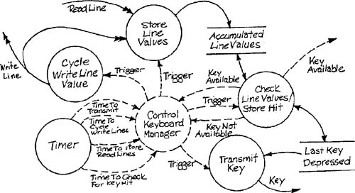
Notice that the model just presented is completely non-specific to the SILLY system — it will work with any application that requires keyboard input. The keyboard management system has its own specific semantic level, expressed here in terms of the structural details of the model and in terms of the naming of model elements.
If an implementation environment is reasonably complex, it may be necessary to define system utilities recursively. In other words, in order to implement a utility successfully, a second utility with a different semantic level might have to be defined. The second utility bears the same relationship to the first as the first does to the original application — the relation of providing a support environment. The levels of the ISO network architecture protocol [1] bear this relationship to one another, with each lower layer acting as a support environment for the upper layers.
System utilities may be categorized in terms of the relationship they bear to the essential model for which they provide support. The categories are:
interface utilities that enable the data and control signals described by the essential model to be sent and received in a particular implementation environment,
transformation utilities that actually carry out some of the work described by the essential model, and
control utilities that manage the dynamics of the essential model transformations.
A fourth type of utility, one that provides the interface between the essential model transformations and the system’s stored data, will be considered in detail in the next chapter.
Interface utilities are chosen to provide a buffer between the essential model and the details of sensor/actor technology, communication links such as data entry or display mechanisms, and the like. Interface utilities often constitute what Britton, Parker, and Parnas [2] have called a virtual device. In the ideal case, the utilities permit the application code to be written as though the simplest conceptual picture of the system inputs and outputs (that is, the essential model view) could be implemented directly.
Let’s return to the job of making keyboard input from the SILLY system operator available to the application tasks. A utility to manage the keyboard mechanism and to send a data representation of the key that was depressed was described in Section 3 of this chapter. We will assume that the keyboard manager is implemented by a dedicated digital circuit, and that the digital circuit is interfaced to a processor that contains the SILLY application tasks. The interface to the processor consists of the Key Available signal, which acts as an interrupt, and the Key data, which is sent through a data line. Figure 6.7 illustrates the connections. The application task may be thought of as waiting for a command. When the keyboard manager interrupts, the operating system saves the environment of the application task and transfers control to a data line handler that receives and stores the data from the data line. When the data line handler is finished, the operating system restores the environment of the application task and reactivates it. The entire mechanism is invisible to the application task, which, when reactivated, finds that a command has suddenly appeared.

It can be seen from the last example that an interface utility can be a dedicated processor like the keyboard manager, or a task within a processor like the data line handler. An interface utility could also be implemented as a subordinate routine called within an application task.
Although the ideal implementation environment is invisible to the application code, there are portions of interactive interfaces so application-specific that they may not be worth defining as general-purpose utilities. Let’s once more turn to the example of SILLY. In the essential model, user commands simply “flow” to the appropriate transformation with no routing necessary. If the essential model transformations are implemented by separate tasks within a processor, and if the commands come from a single source (the Command store in Figure 6.7), some mechanism to distribute the commands to the appropriate tasks is necessary. Although a general purpose “command-to-task distributor” could be defined, it can be argued that the distribution mechanism is better incorporated within the implementation model, as illustrated in general terms by Figure 6.8.

The second category of system utility is a transformation utility. Unlike interface utilities, transformation utilities actually do some of the work described by the essential model. Mathematical utilities, such as those for differential and integral equation solution, fall into this category.
Transformation utilities can be identified by generalization from the essential model. In other words, the modeler identifies part of an essential model transformation that is a special case of a more general transformation, and defines the work to be done at the more general semantic level. As an example, consider the transformation specification for Check Sheet Statuses from the Defect system (Appendix B of Volume 2). The logic describes checking for specific location values corresponding to the positions of the scanner, chopper, and other inspection surface components, and issuing a specific event flow when such a location is found. If the idea of data abstractions is applied, this can be seen as a special case of checking an input value V against an array of significant values SV(I) where I ranges from 1 to N, and issuing a message M(J) corresponding to the index J if V = SV(J) for some J in the range of 1 to N. The essential model work could thus be implemented by defining such a table for the inspection surface and executing the appropriate utility routine (or possibly a single processor instruction).
Transformation utilities are commonly implemented as tasks or portions of tasks subordinated by a call relationship to the application code.
The third category of system utility is a control utility. Like transformation utilities, control utilities implement portions of the essential model. However, instead of transforming application data, control utilities implement the dynamic structure of the essential model. This is done by incorporating a portion of an essential model state transition diagram; a control utility may implement a state transition, or permit the operation of concurrent transformations.
The need for control utilities often arises when essential model transformations have been allocated to separate tasks within a single processor. For example, in the Bottling System (Appendix B in Volume 2), assume that the Control Input Valve and Control pH transformations have been assigned to separate tasks. Since these transformations must operate over the same time period, some element of the system above the level of the individual tasks must simulate the concurrency. The operation of the tasks could be managed by a general-purpose task dispatching utility, which uses a table of task IDs and required activation rates. Such a utility could also manage state transitions by maintaining a table of task statuses (active or passive) as a function of state. A given task would be activated at a particular time only if its status were active.
Like transformation utilities, control utilities are identified by generalization from the essential model. Operating systems, in fact, are very general control utilities that provide processing and memory resources to other pieces of software within a processor at appropriate times.
We have advocated defining system utilities by building models that are separate from the implementation models of the primary system to be built. However, these separate models must have sufficient detail to permit integration of the application and the utilities when the system is built and run. The discussion in this section will focus mostly on references to system utilities from the application model, but can also be applied to the reverse situation.
Effective ways to reference a system utility from an implementation model parallel the actual connection between the implemented systems. Let’s consider three types of connections – calls, communication areas, and configuration data – in terms of the binding time of the connection and of the type of data involved.
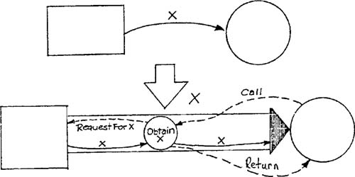
A call consists of the setup by the calling routine of a data structure (parameter list) to be made available to the called routine, plus the actual transfer and return of control. The call mechanism operates at run time, and the data transferred is usually subject-matter data as defined by the essential model. It is important to recognize that a call is the implementation of a flow or store connection and does not change the overall structure of a model (Figure 6.9).
Therefore a call can be represented as an annotation on a data specification, or as an annotation on a transformation specification. Figure 6.10 shows a task within the SILLY implementation model.
The flow Trigger Word Command is a composite of the keyboard commands used in conjunction with a trigger word modification. If the keyboard input is to be obtained by a call, the data specification can be made accordingly:
Trigger Word Command | = | [0 | 1 | 2...F | Scroll Left | Scroll Right | Bin | Hex] |
*implement using the READKBD call – stored in library #XYZ * | ||
If a specific type of call to obtain or send data is to be used by a number of tasks, the annotation can be made on the data specification of a high-level composite flow incorporating all of the lower-level flows:
User Command | = | [Logic Acquisition Command | Trigger Command | Display Manipulation Command] |
*implement using the READKBD call - stored in library XYZ* |
The call just described activates an interface utility and implements a flow connection from the environment to the system. Calls to transformation utilities often implement an internal flow connection between fragments of a transformation. Therefore the use of the call can be documented as an annotation of the transformation specification. In the example of the Check Sheet Statuses transformation in Section 6.4 of this chapter, the comment:
*use calls to TABLEINIT, TABLECHECK as per library #ABC*
could be added to the transformation specification.
A communication area is simply a segment of memory known to both an application task and a system utility and used to communicate data. A communication area is often defined at load time by means of an external variable declared within the application task, and is used to transfer application data. The use of a communication area is an implementation of a flow or store connection as is the call, and can be documented in the implementation model in the same way. For example, if keyboard commands in SILLY were to be implemented by a communication area, the appropriate data specification could be annotated with
*Define a one-byte external variable EXKBD.*
The use of communication areas places more responsibility on the application code than does the use of calls. In the example just given, the task that receives keyboard input has no external protection against checking the communication area several times between changes made by the utility, and concluding that several identical commands have been issued. Please refer to the discussion in Section 5.3 of Chapter 5, Interface Modeling.
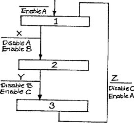
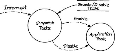
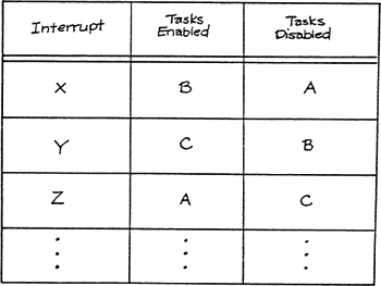
Configuration data refers to data about the structure of a model, or about the connections between models, rather than to subject-matter data transformed by a system. Configuration data often consists of a representation in data terms of the patterns of movement of data and control of an implementation model. For example, let’s assume that conditions X, Y, and Z on the state transition diagram of Figure 6.11 are to be implemented as interrupts. If the activation and deactivation of tasks is to be handled by a table-driven task dispatcher (as modeled in Figure 6.12), the implementation model should contain a tabular form of the state transition diagram as a supplement to the graphic model, as shown in Table 6.1. The structure of the essential model is therefore represented as data within the utility.
Configuration data about the structure of the essential model can be made available to a system utility at compile time or at load time. However, data about connections between an application task and a utility can be dynamic, in which case it will have to be modifiable at run time. If system outputs are displayed on a screen by a graphics handler, for example, the user may need to change the graphic representation of a specific output as the system is operating. The transformations that handle the run-time modification of configuration data are at a semantic level “between” the semantic levels of the application and the utility. Such transformations may be incorporated into the implementation model of the application, or may be modeled separately as a configuration data utility.
When a “family” of related systems is to be implemented by a systems development project, a set of well-designed utilities can significantly reduce the work required. The ideal is to build for each system in the family a minimal superstructure of application-specific code. Within this superstructure, pre-existing utilities may be assembled tinker-toy fashion to create a working system. The UNIX® system provides a set of utilities of this type together with a powerful mechanism for creating a superstructure.
An effective implementation strategy requires careful separation of subject-matter-specific details from details that can be handled by general systems support utilities. To attain this end, it is important to be able to visualize a support utility as a system in its own right, divorced from the semantics of the application it will support. This chapter has presented guidelines for identifying required support functions and for building models of system utilities.