
Chapter 13 Gears, Bearings, and Cams
13-1 Introduction
This chapter explains how to draw and design with gears and bearings. The chapter does not discuss how to design specific gears and bearings, but how to design by using existing parts selected from manufacturers’ catalogs. Various gear terms are defined, and design applications demonstrated.
The chapter also discusses how to design and draw a cam according to a displacement diagram. Different types of follower motion are explained, as well as different types of followers.
13-2 Types of Gears
There are many types of gears, including spur, bevel, worm, helical, and rack. See Figure 13-1. Each type has its own terminology, drawing requirements, and design considerations.
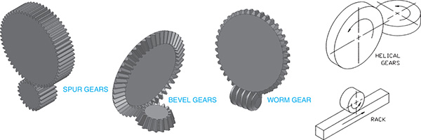
Figure 13-1
13-3 Gear Terminology—Spur
Following is a list of common spur gear terms and their meanings. Figure 13-2 illustrates the terms, and Figure 13-3 shows a listing of relative formulas.

Figure 13-2

Figure 13-3
For Spur Gears Using English Units
Pitch diameter (PD)—The diameter used to define the spacing of gears.
Diametral pitch (DP)—The number of teeth per inch or millimeter.
Circular pitch (CP)—The circular distance from a fixed point on one tooth to the same position on the next tooth, as measured along the pitch diameter. The circumference of the pitch diameter divided by the number of teeth.
Preferred pitches—The standard sizes available from gear manufacturers. Whenever possible, use preferred gear sizes.
Center distance (CD)—The distance between the center points of two meshing gears.
Backlash—The difference between a tooth width and the engaging space on a meshing gear.
Addendum (a)—The height of a tooth above the pitch diameter.
Dedendum (d)—The depth of a tooth below the pitch diameter.
Whole depth—The total depth of a tooth. The addendum plus the dedendum.
Working depth—The depth of engagement of one gear into another. Equal to the sum of the two gear addendums.
Circular thickness (CT)—The distance across a tooth as measured along the pitch diameter.
Face width (FW)—The distance from front to back along a tooth, as measured perpendicular to the pitch diameter.
Outside diameter (OD)—The largest diameter of the gear. Equals the pitch diameter plus the addendum.
Root diameter (RD)—The diameter of the base of the teeth. The pitch diameter minus the dedendum.
Clearance—The distance between the addendum of a meshing gear and the dedendum of the mating gears.
Pressure angle—The angle between the line of action and a line tangent to the pitch diameter. Most gears have pressure angles of either 14.5° or 20°.
For Spur Gears Using Metric Units
The preceding definitions apply to both English unit and metric unit spur gears, with the exception of pitch. For English unit gears, pitch is defined as the number of teeth per inch relative to the pitch diameter and is expressed by the formula shown in Figure 13-4. Gears made to metric specifications are defined in terms of the amount of pitch diameter per tooth, called the gear’s module. Figure 13-4 shows the formula for calculating a gear’s module. Metric gears also have a slightly different tooth shape that makes them incompatible with English unit gears.

Figure 13-4
13-4 Spur Gear Drawings
Figure 13-5 shows a representation of spur gears. The individual teeth are not included in the front view, but are represented by three phantom lines. The diameters of the three lines represent the outside diameter, the pitch diameter, and the root diameter.

Figure 13-5
The outside diameter and the pitch diameter are usually given in manufacturers’ catalogs. The root diameter can be calculated from the pitch diameter by the formula presented in Figure 13-3.
The side view of the gear is drawn as a sectional view taken along the vertical centerline. The gear size is defined by using the manufacturer’s stock number, dimensions, and a list of appropriate design information.
Figure 13-6 shows the front representation view of three meshing gears. The gears are positioned so that the pitch circle diameters are tangent. Ideally, mating gears always should mesh exactly tangent to their pitch circles.

Figure 13-6
Gear representations were developed because it was both difficult and time consuming to accurately draw individual teeth when creating drawings on a drawing board. The AutoCAD Array and Block commands, among others, can be used to create detailed gear drawings that include all teeth; however, it is usually sufficient to show a few meshing teeth and use the representative centerlines for the remaining portions of both gears. See Figure 13-7.

Figure 13-7
Most gear tooth shapes are based on an involute curve. Involute-based teeth fit together well, transfer forces smoothly, and can use one cutter to generate all gear tooth variations within the same pitch. Standards for tooth proportions have been established by the American National Standards Institute (ANSI) and the American Gear Manufacturers Association (AGMA).
13-5 Sample Problem SP13-1
Draw a front view of a spur gear that has an outside diameter of 6.50 inches, a pitch diameter of 6.00 inches, and a root diameter of 5.25 inches. The gear has 12 teeth.
The method presented is a simplified method and is an acceptable representation for most drawing applications. See Figure 13-8.

Figure 13-8
 Draw three concentric circles of diameter 6.50, 6.00, and 5.25. Use the Center Mark command modified to draw a centerline for the circles.
 Use the Array command and create 48 ray lines as shown. Label three rays on each side of the top vertical centerline as shown. Zoom the labeled area.
The number of rays should equal four times the number of teeth to be drawn. Two adjoining sectors are used to define the width of the tooth, and the next two adjacent sectors are used to define the space between teeth.
 Draw a circle whose center point is at the intersection of the pitch diameter and the ray labeled 2, and whose radius is determined by the distance from the center point to the intersection of the pitch diameter and the ray labeled –1.
 Repeat step 3, using the intersection of the pitch diameter and the point labeled –2 as the center point.
 Use the Fillet command to draw a radius at the base of the tooth. Select the side of the tooth as one of the lines for the fillet, and the root diameter as the other line.
Both the circle and ray line will be within the selected cursor, but AutoCAD will select the last entity drawn, so the diameter will be selected.
The tooth shape can be saved as a wblock named TOOTH and used when drawing other gears. Only the lines that represent the top of the gear and the two side sections need to be saved. A different size gear will have a different root diameter, and new fillets can be drawn that align with the new root diameter.
 Use the Trim and Erase commands to remove excess lines and create the tooth shape between rays 22 and 2 as shown.
This tooth shape may be saved as a wblock and used when drawing other gears.
 Array the tooth shape about the gear’s center point.
 Erase the excess ray lines and change the pitch diameter to a centerline.
 Draw the gear’s bore hole or center hole and hub, as required.
13-6 Sample Problem SP13-2
Figure 13-9A shows two meshing gears. In the example shown, the larger gear has a diameter of 6.00 inches with 24 teeth; the smaller gear has a diameter of 3.00 inches and 12 teeth. The drawing utilizes the wblock created in Sample Problem SP13-1 as follows.

Figure 13-9A
The circular thickness of the wblock tooth as measured along the pitch diameter equals 1/12 the circumference of the pitch diameter.
(1/12)(π PD)
For the gear in SP13-1, where PD = 6
The large gear requires 24 teeth on a pitch diameter of 6, or twice as many teeth as the gear used to create the wblock. The teeth on the 24-tooth gear must be half the size of the tooth created in the wblock. The teeth on the smaller gear must be the same size as the teeth on the larger gear.
To Draw Meshing Spur Gears (See Figure 13-9B.)

Figure 13-9B
- Draw two circles of diameter 6.00 and 3.00 inches. Include the circles’ centerlines. Use Setvar, Dimcen, set to –.2, or use a modified Center Mark tool.
The gears will be drawn separately and then meshed.
- Insert the TOOTH wblock on both gears as shown on the pitch diameter. Use an X and Y scale factor of .5. Explode the wblock.
- Use the Array command to create the required 24 and 12 teeth.
- Draw a line between the roots of two of the teeth as shown. Use the Array command to create the root circle. Add the fillet to each tooth base.
The line in this example is a straight line acceptable for smaller gears. If more accuracy of shape is required, draw a complete root circle and then trim all of it away except the portion between two tooth roots. Array this sector between all of the other teeth.
- Use the Rotate command to orient the small gear with the large gear.
Each tooth on the large gear requires 360/24 = 15°. Rotate the smaller gear 15°.
- Use the Move command to position the small gear.
The pitch circles of the two gears should be tangent.
- Rotate the smaller gear’s centerline –15°.
- Add the center hubs to both gears as shown.
13-7 Sample Problem SP13-3
Figure 13-10 shows a gear that has a pitch diameter of 4.00 with 18 teeth. The TOOTH wblock can be used as follows.

Figure 13-10
The wblock is first reduced to accommodate the smaller diameter.
- Draw a circle with a 4.00-inch diameter. Include centerlines.
- Insert the wblock, using an X and Y scale factor of .4445.
The scale factor was derived by considering the ratio between the number of teeth on the gear used to create the TOOTH wblock (12) and the number of teeth on the desired gear, 18, or 12/18 = .6667. The ratio between the diameters is also considered: 4.00/6.00 = .6667. The two ratios are multiplied together: (.6667)(.6667) = .4445.
- Use the Array command to create the required 18 teeth.
- Draw a line between the end lines of two of the teeth, and array the line 18 times around the gear.
The line may be drawn as a straight line for small gears or as an arc for larger gears. The arc may be created by drawing a circle, then using the Trim command to create the desired length.
- Add the center hub as required.
The same wblock can be used for metric gears, using the conversion factor 1.00 inch = 25.4 millimeters. It is probably easier to create a separate wblock for a metric tooth.
13-8 Selecting Spur Gears
When two spur gears are engaged, the smaller gear is called the pinion gear and the larger gear is called simply the gear. The relationship between the relative speed of two mating gears is directly proportional to the gears’ pitch diameters. Also, the number of teeth on a gear is proportional to the gear’s pitch diameter. This means that the ratio of speed between two meshing gears is equal to the ratio of the number of teeth on the two gears. If one gear has 40 teeth and the other 20, the speed ratio between the two gears is 2:1.
For gears to mesh properly, they must have the same pitch and pressure angle. Gear manufacturers present their gears in charts that include a selection of gears with common pitches and pressure angles. Figure 13-11 shows a sample spur gear listing from the website of Stock Drive Products. The site allows you to select a diametral pitch and all other appropriate product details. Once a gear is selected, the gear information will be displayed. You may be able to generate an AutoCAD drawing of the gear if you have a compatible setup. Many manufacturers offer free product catalogs.

Figure 13-11 Courtesy of Stock Drive Products/Sterling Instrument, a division of Designatronics, Inc., sdp-si.com
13-9 Center Distance Between Gears
The center distance between meshing spur gears is needed to align the gears properly. Ideally, gears mesh exactly on their pitch diameters, so the ideal center distance between two meshing gears is equal to the sum of the two pitch radii, or the sum of the two diameters divided by 2:
CD1 = (PD1 + PD2)/2
If two gears were chosen from the chart in Figure 13-11, and one had 30 teeth and a pitch diameter of .9375 and the other had 60 teeth and a pitch diameter of 1.8750, the center distance between the gears would be
CD1 = (.9375 + 1.8750)/2 = 1.4062
The center distance of gears is dependent on the tolerance of the gears’ bores, the tolerance of the supporting shafts, and the feature and positional tolerance of the holes in the shaft’s supporting structure. The following sample problem shows how these tolerances are considered and applied when matching two spur gears.
13-10 Sample Problem SP13-4
An electric motor generates power at 1750 rpm. Reduce this speed by a factor of 2, using steel metric gears with a module of 1.5 and a pressure angle of 20°. Figure 13-12 shows a list of gears. Determine the center distance between the gears, and specify the shaft sizes required for both gears.

Figure 13-12 Courtesy of Stock Drive Products/Sterling Instrument, a division of Designatronics, Inc., sdp-si.com
Gears number A 1C22MYKW150 50A and number A 1C22MKYW150 100A were selected from the chart shown in Figure 13-12. The pinion gear has 50 teeth, and the large gear has 100, so if the pinion gear is mounted on the motor shaft, the larger gear will turn at 875 rpm, or half of the 1750 rpm motor speed.
The specific design information for the selected gears is as follows:
The center distance between the gears is equal to the sum of the two pitch diameters divided by 2:
The manufacturer’s catalog lists the bore tolerance as an H7. One gear has a nominal bore diameter of 20, and the other one of 25. Standard fit tolerances for metric values are discussed in Chapter 9, and appropriate tables are included in the online appendix.
Tolerance values for a sliding fit (H7/g6) hole basis were selected for this design application. This means that the shaft tolerances are 19.993 and 19.980 for the pinion gear and 24.993 and 24.980 for the large gear.
13-11 Combining Spur Gears
Gears may be mounted on the same shaft. Gears on a common shaft have the same turning speed. Combining gears on the same shaft enables the designer to develop larger gear ratios within a smaller space.
Combining gears can also be used to help reduce the size of gear ratios between individual gears and the amount of space needed to create the reductions. Figure 13-13 shows a four-gear setup. Gears B and C are mounted on the same shaft. Gear A is the driver gear and is turning at a speed of 1750 rpm. The speed of gear D is determined as follows.

Figure 13-13
The ratio between gears A and B is
The speed of gear B is therefore
Gears B and C are on the same shaft, so they have the same speed. Gear C is turning at 1166.7 rpm.
The ratio between gears C and D is
The speed of gear D is therefore
The ratio between gears A and D is 3:1.
13-12 Gear Terminology—Bevel
Bevel gears align at an angle with each other. An angle of 90° is most common. Bevel gears use much of the same terminology as spur gears, but with the addition of several terms related to the angles between the gears and the shape and position of the teeth. Figure 13-14 defines the related terminology.

Figure 13-14 Courtesy of Stock Drive Products/Sterling Instrument, a division of Designatronics, Inc., sdp-si.com.
Bevel gears must have the same pitch or module value and have the same pressure angle for them to mesh properly. Manufacturers’ catalogs usually list bevel gears in matched sets designated by ratios that have been predetermined to fit together correctly. Figure 13-15 shows a sample list of matched set bevel gears with millimeter values, and Figure 13-16 shows a list for inch values.

Figure 13-15 Courtesy of Stock Drive Products/Sterling Instrument, a division of Designatronics, Inc., sdp-si.com

Figure 13-16 Courtesy of Stock Drive Products/Sterling Instrument, a division of Designatronics, Inc., sdp-si.com
13-13 How to Draw Bevel Gears
Bevel gears are usually drawn by working from dimensions listed in manufacturers’ catalogs for specific matching sets. The gears are drawn by using either a sectional view or a half-sectional view that shows the profiles of the two gears. Figure 13-17 shows a matching set of bevel gears that were drawn from the information given in Figure 13-15.

Figure 13-17
The procedure used to draw the gears, based on information given in manufacturers’ catalogs, is as follows.
To Draw a Matched Set of Beveled Gears
- Draw a perpendicular centerline pattern, and use the Offset command to define the pitch diameters of the pinion and gear.
- Extend the pitch diameter lines, and draw lines from the center point to the intersections as shown.
These lines are called the face angle lines. The ends of beveled gears are drawn perpendicular to the face angle lines. Gear manufacturers do not always include the outside diameter values with matching sets of gears. The values are sometimes listed, with data for the individual gears elsewhere in the catalog. If the outside diameter values are not given, they can be conservatively estimated by drawing the addendum angle approximately –5.0° from the face angle and the dedendum 6.0° from the face angle.
The perpendicular end lines may be constructed by use of the Copy and Rotate commands. Copy the existing face angle line directly over the existing line, and rotate the line 90° from the face angle line.
Use the Extend command to extend the rotated lines as needed. Add a construction line to help define an intersection between the dedendum ray line and the face line perpendicular to the face angle line. Trim and erase any excess lines.
- Use the Copy and Rotate commands to copy the face shape and rotate it into the two other positions shown.
- Use the given dimensions to complete the profiles. Erase and trim lines as necessary.
- Draw the bore holes and holes for the setscrews according to the manufacturer’s specifications.
- Use the Hatch command to draw the appropriate hatch lines.
The two gears should have hatch patterns at different angles. In this example, the hatch pattern on the pinion is at 90° to the pattern on the gear.
13-14 Worm Gears
A worm gear setup is created by using a cylindrical gear called a worm and a circular matching gear called a worm gear. See Figure 13-18. As with other types of gears, worm gears must have the same pitch and pressure angle in order to mesh correctly. Manufacturers list matching worms and worm gears together in their catalogs. Figure 13-20 shows a gear manufacturer’s listing for a worm gear and the appropriate worms.

Figure 13-18
Worm gears are drawn according to the representation shown in Figure 13-20 or by using sectional views as shown in Figure 13-19. The worm teeth shown can be drawn by the procedure for acme threads explained in Chapter 11.

Figure 13-19

Figure 13-20 Courtesy of WM Berg Inc. Copyright © 2019 WM Berg. Berg is a division of Rexnord.
The relationship between worm gears is determined by the lead of the worm thread. The lead of a worm thread is similar to the pitch of a thread discussed in Chapter 11. Worm threads may be single, double, or quadruple. If a worm has a double thread, it will advance the gear twice as fast as a worm with a single thread.
13-15 Helical Gears
Helical gears are drawn as shown in Figure 13-21. The two gears are called the driver and the driven, as indicated. Figure 13-22 shows a manufacturer’s listing of compatible helical gears.

Figure 13-21 Courtesy of Stock Drive Products/Sterling Instrument, a division of Designatronics, Inc., sdp-si.com
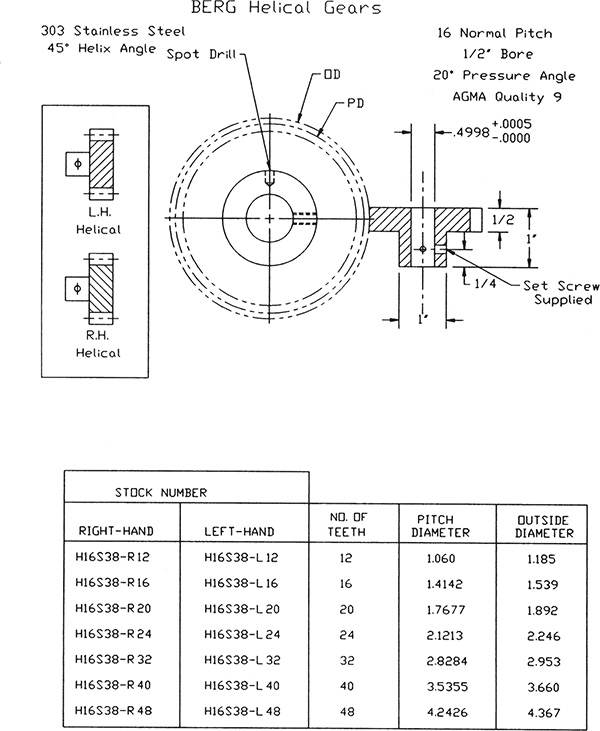
Figure 13-22 Courtesy of WM Berg Inc. Copyright © 2019 WM Berg. Berg is a division of Rexnord.
Helical gears may be manufactured with either left- or right-hand threads. Left- and right-hand threads are used to determine the relative rotation direction of the gears.
13-16 Racks
Racks are gears whose teeth are in a straight row. Racks are used to change rotary motion into linear motion. See Figure 13-23. Racks are usually driven by a spur gear called a pinion.

Figure 13-23 Courtesy of Stock Drive Products/Sterling Instrument, a division of Designatronics, Inc., sdp-si.com
One of the most common applications of gear racks is the steering mechanism of an automobile. Rack-and-pinion steering helps create a more positive relationship between the rotation of the steering wheel and the linear input to the car’s wheel than did the mechanical linkages used on older-model cars.
Figure 13-24 shows a manufacturer’s list for racks. The rack and pinions must have the same pitch and pressure angle to mesh correctly.

Figure 13-24 Courtesy of WM Berg Inc. Copyright © 2019 WM Berg. Berg is a division of Rexnord.
13-17 Ball Bearings
Ball bearings are used to help eliminate friction between moving and stationary parts. The moving and stationary parts are separated by a series of balls that ride in a race.
Figure 13-25 shows a listing for ball bearings that includes applicable dimensions and tolerances, which is from the Stock Drive Products website. There are many other types and sizes of ball bearings available.

Figure 13-25 Courtesy of Stock Drive Products/Sterling Instrument, a division of Designatronics, Inc., sdp-si.com
Ball bearings may be drawn as shown in Figure 13-25 or by using one of the representations shown in Figure 13-26. It is recommended that the representations be drawn and saved as wblocks for use on future drawings.

Figure 13-26
The outside diameter of the bearings listed in Figure 13-25 has a tolerance of +.0000/–.0002. The same tolerance range applies to the center hole. These tight tolerances are manufactured because this type of ball bearing is usually assembled by using a force fit. See Chapter 9 for an explanation of fits. Ball bearings are available that do not assemble by the use of force fits.
The following sample problem shows how ball bearings can be used to support the gear’s shafts.
13-18 Sample Problem SP13-5
Figure 13-27 shows two spur gears and a dimensioned drawing of a shaft used to support both gears. Design a support plate for the shafts. Use ball bearings to support the shafts. Specify dimensions and tolerances for the support plate, and assume that the bearings are to be fitted into the support plate by the use of an LN2 medium press fit. The tolerance for the center distance between the gears is to be +.001, –.000.

Figure 13-27 Courtesy of WM Berg Inc. Copyright © 2019 WM Berg. Berg is a division of Rexnord.
The maximum interference permitted for an LN2 medium press fit is .0011. See the fits tables in the online appendix. For purposes of calculation, the bearing is considered to be the combination of the shaft and the holes in the support plate.
Maximum interference occurs when the shaft (bearing) is at its maximum diameter and the hole (support plate) is at its minimum. The maximum shaft diameter, the maximum diameter of the bearing, is .5000, as defined in the manufacturer’s listing. This means that the minimum hole diameter should be .5000 – .0011 = .4989. An LN2 fit has a hole tolerance of +.0007, so the maximum hole size should be .4989 + .0007 =.4996.
The minimum interference, or the difference between the minimum shaft diameter and the maximum hole diameter, is .4998 – .4996 =.0002. There will always be at least .0002 interference between the ball bearing and the hole.
The bore of the selected bearing, listed in Figure 13-25, has a limit tolerance of .2500 – .2498. The shafts specified in Figure 13-27 have a limit tolerance of .2497 – .2495. This means that there will always be a slight clearance between the shaft and the bore hole.
The nominal center distance between the two gears is 3.000 inches. The given tolerance for the center distance is +.001, –.000. This tolerance can be ensured by assigning a positional tolerance of .0005 to each of the two holes applied at maximum material condition at the centerline. The base distance between the two holes is defined as 3.0000. The maximum center distance, including the positional tolerance, is 3.0000 + .0005 = 3.0005, and the minimum is 3.0000 – .0005 = 2.9995, or a total maximum tolerance of .001.
Figure 13-28 shows a detail drawing of the support plate.

Figure 13-28
13-19 Bushings
A bushing is a cylindrically shaped bearing that helps reduce friction between a moving part and a stationary part. Bushings, unlike ball bearings, have no moving parts. Bushings are usually made from oil-impregnated bronze or Teflon. Figure 13-29 shows a manufacturer’s list of bronze bushings, and Figure 13-30 shows a list for Teflon bushings.

Figure 13-29 Courtesy of WM Berg Inc. Copyright © 2019 WM Berg. Berg is a division of Rexnord.

Figure 13-30 Courtesy of WM Berg Inc. Copyright © 2019 WM Berg. Berg is a division of Rexnord.
Bushings are cheaper than ball bearings, but they wear over time, particularly if the application is high speed or one with heavy loading. Bushings are usually pressed into a supporting plate. Gear shafts must always have clearance from the inside diameters of bushings.
13-20 Sample Problem SP13-6
Figure 13-31 shows two support plates used to support and align a matched set of bevel gears. The gears selected are numbered S1346Z–48S30S60 in the listings presented in Figure 13-16. The calculations are similar to those presented earlier for Sample Problem SP13-5, but with the addition of tolerances for the holes and machine screws used to join the two perpendicular support plates together.

Figure 13-31
Figure 13-31 shows an assembly drawing of the two gears along with appropriate bushings, stock number B6 11 from Figure 13-29, and shafts and supporting parts 1 and 2. The figure also shows detail drawings of the two support plates with appropriate dimensions and tolerances.
The bushings are fitted into the support plates by the use of an FN1 fit. The fit tables in the online appendix define the maximum interference for an FN1 fit as .0075 and the minimum interference as .0001. The outside diameter of the bushing has a tolerance of .3770 – .3760, per Figure 13-29. The feature tolerances for the holes in the support parts are found as follows:
Shaft max – Hole min = Interference max
Shaft min – Hole max = Interference min
The feature tolerance for the hole is therefore .3750 – .3695.
The positional tolerance is determined as described in SP13-5 and is based on a tolerance of 0.001 between gear centers.
13-21 Cam Displacement Diagrams
A displacement diagram is used to define the motion of a cam follower. Displacement diagrams are set up as shown in Figure 13-32. The horizontal axis is marked off in 12 equal spaces that represent 30° on the cam. The vertical axis is used to define the linear displacement of the follower and is defined either in inches or in millimeters.

Figure 13-32
The vertical axis of a displacement diagram must be drawn to scale because, once defined, the vertical distances are transferred to the cam’s base circle to define the cam’s shape. Figure 13-32 shows distances A, B, and C on both the displacement diagram and cam. The distances define the follower displacement at the 30°, 60°, and 90° marks, respectively.
The horizontal axis may use any equal spacing to indicate the angle because the vertical distances will be transferred to the cam along ray lines. The lower horizontal line represents the circumference of the base circle.
Figure 13-33 shows a second displacement diagram. Note how the distance between the 60° and 90° lines has been further subdivided. The additional lines are used to more accurately define the cam motion. Additional degree lines are often added when the follower is undergoing a rapid change of motion.
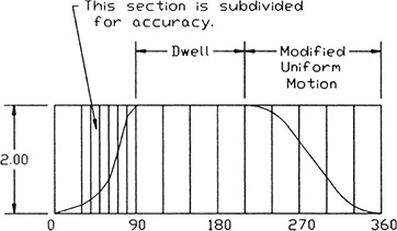
Figure 13-33
The term dwell means that the cam follower does not move either up or down as the cam turns. Dwells are drawn as straight horizontal lines on a displacement diagram. Note the horizontal line between the 90° and 210° lines on the displacement diagram shown in Figure 13-33. Dwells are drawn as sectors of constant radius on the cam.
To Set Up a Displacement Diagram
See Figure 13-34. The given dimensions are in inches. The values in the brackets, [ ], are in millimeters.
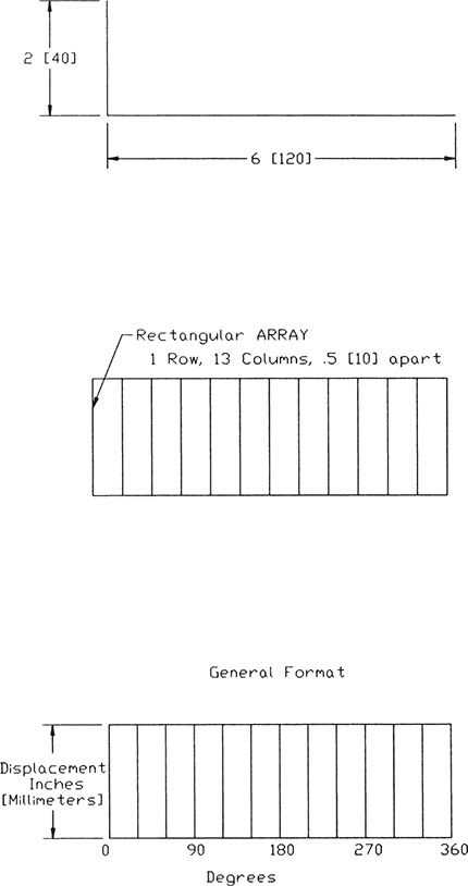
Figure 13-34
- Set Grid = .5 [10]
Snap = .25 [5]
- Draw a horizontal line 6 [120] long.
- Draw a vertical line 2 [40] from the left end of the horizontal line as shown.
The length 2 [40] was chosen arbitrarily for this example. The vertical distance should be equal to the total displacement of the follower.
- Use the Array command to create a rectangular array with 12 columns .5 [10] apart. Draw a horizontal line across the top of the diagram.
- Label the horizontal axis in degrees, with each vertical line representing 30°, and the vertical axis in inches [millimeters] of displacement.
13-22 Cam Motions
The shape of a cam surface is designed to move a follower through a specific distance. The surface also determines the acceleration, deceleration, and smoothness of motion of the follower. It is important that a cam surface be shaped to maintain continuous contact with the follower. Several standard cam motions are defined next.
Uniform Motion
Uniform motion is drawn as a straight line on a displacement diagram. See Figure 13-35. The follower rises the same distance for each degree of rotation by the cam.

Figure 13-35
Modified Uniform Motion
Modified uniform motion is similar to uniform motion, but has a curved radius shape added to each end of the line to facilitate a smooth transition from the uniform motion to another type of motion or to a dwell section.
Figure 13-36 shows how to create a modified uniform motion on a displacement diagram. The procedure is as follows:
- Set up a displacement diagram, as presented in the preceding section.
- Draw two arcs or circles of radius no greater than half of the required displacement.

Figure 13-36
Any radius value can be used. In general, the larger the radius is, the smoother the transition will be. In the example shown, a radius equal to half of the total displacement was used.
- Use Osnap Tangent, and draw a line between the two arcs.
- Erase and trim any excess lines.
Harmonic Motion
Figure 13-37 shows how to create a harmonic cam motion. The procedure is as follows:
- Set up a displacement diagram as presented in Section 13-21.
- Draw a semicircle aligned with the left side of the displacement diagram. The diameter of the semicircle equals the total height of the displacement.

Figure 13-37
- Use the Array command or the Line command with relative coordinate inputs, and draw rays every 30° on the circle, as shown. Label the rays from 0° to 180° in 30° segments.
- Use Osnap Intersection with Ortho on, <F8>, and draw projection lines from the intersections of the rays with the circumference of the circle across the displacement diagram.
- Draw a polyline that starts at the lower left corner of the diagram and connects the intersections of like angle lines.
For this example, the horizontal line from the circle’s 30° increment intersects with the vertical line from the 30° mark on the displacement diagram.
- Use the Edit Polyline, Fit option to change the straight polyline into a smooth curved line.
- Project the same lines to the far side of the diagram to define the deceleration harmonic motion path.
Uniform Acceleration and Deceleration
Uniform acceleration and deceleration are based on the knowledge that acceleration is related to distance by the square of the distance. Acceleration is measured in distance per second squared. Distances of units 1, 2, and 3 may be expressed as 1, 4, and 9, respectively.
Uniform acceleration and deceleration motions create smooth transitions between various displacement heights and are often used in high-speed applications.
Figure 13-38 shows how to create a uniform acceleration cam motion. The procedure is as follows:
- Set up a displacement diagram as presented in Section 13-21.
- Draw a horizontal construction line to the left, and align it with the bottom horizontal line of the displacement diagram.
- Use the Array command, and create 1 column and 19 rows, .1111 apart.

Figure 13-38
The 19 rows create 18 spaces. The uniform motion shape is created by combining six horizontal steps (30°, 60°, 90°, 120°, 150°, 180°) and the squares of six vertical steps (1, 4, 9, 4, 1, 0).
The vertical spacing is symmetrical about the centerline of the displacement diagram, so the original spacing is 1, 2, 3, 2, 1. The square of these values is used to create the uniform acceleration and deceleration.
The .1111 value was derived by dividing the displacement distance by the number of spaces, 2.00/18 = .1111.
- Label the stack of vertical construction lines as shown.
- Use the Extend command to extend the horizontal construction lines so that they intersect with the appropriate vertical degree line.
- Use the Edit Polyline command’s Fit option to create a smooth, continuous curve between the 0° and 180° lines.
The same line may be used to create a deceleration curve as shown.
13-23 Cam Followers
There are two basic types of cam followers: those that roll as they follow the cam’s surface, and those that have a fixed surface which slides in contact with the cam surface. Figure 13-39 shows an example of a roller follower and a fixed- or flat-surface follower. The flat-surface-type followers are limited to slow-moving cams with low force requirements.

Figure 13-39
Followers are usually spring loaded to keep them in contact with the cam surface during operation. Springs were discussed in Section 11-24.
13-24 Sample Problem SP13-7
Design a cam that rises 2.00 inches over 180° by harmonic motion, dwells for 60°, descends 2.00 inches in 90° by modified uniform motion, and dwells the remaining 30°. The base circle for the cam is 3.00 inches in diameter, and the follower is a roller type with a 1.00-inch diameter. The cam will rotate in a counterclockwise direction. The center hole is .75 inch in diameter with a .125 × .875 keyway. See Figures 13-40 and 13-41.

Figure 13-40

Figure 13-41
- Set up a displacement diagram as described in Section 13-21.
- Define a path between the 0° and 180° vertical lines, using the method described for harmonic motion. Draw the required circle on the left end of the diagram as shown.
- Draw a horizontal line from the 180° to the 240° line.
This line defines the follower’s dwell.
- Draw two arcs of .50 radius, one tangent to the top horizontal line of the displacement diagram and the second tangent to the bottom line.
Draw one arc on the 240° line and the other on the 330° line as shown. In this example, the arcs have a radius equal to .25 of the total displacement. Any convenient radius value may be used.
- Use the Osnap Tangent command, and draw a line tangent to the two arcs.
- Erase and trim any excess lines and constructions.
This completes the displacement diagram. The follower distances are now transferred to the cam’s base circle to define the surface shape. See Figure 13-41.
- Draw two concentric circles of 3.00 diameter and 8.00 diameter, respectively.
The 3.00 diameter is the base circle. The 8.00-diameter-circle value is derived from the radius of the base circle, plus the maximum displacement, plus the radius of the follower: 1.50 + 2 + .5 = 4.00 radius, or 8.00 diameter.
- Use the Setvar, Dimcen, –.2, Dim, Center commands, or a modified Center Mark tool, to draw the centerlines for the 8.00 circle.
- Use the Array command, and polar array the top portion of the vertical centerline 12 times around the full 360°.
 Label the ray lines as shown.
Note that the top vertical ray line is labeled as both 0 and 360.
 Transfer the follower distances from the displacement diagram to the cam drawing.
Several different techniques can be used to transfer the distances: Use the Linear dimension tool located on the Dimensions panel under the Annotate tab, or use the Distance command accessed by typing dist in response to a command prompt. Use the Osnap Intersection command to ensure accuracy. In this example, the measured distance values are listed below the displacement diagram in Figure 13-40. The .50 addition to the bottom of the diagram is to account for the .50 follower radius. Note how the distance of 2.1000 was measured.
The distance values can be used to draw lines from the base circle along the appropriate ray line on the cam drawing by the use of relative coordinate values. The values for this example are as follows:
.5000-(0) |
@.5000 < 90 |
.6340-(30) |
@.6340 < 60 |
1.0000-(60) |
@1.0000 < 30 |
1.5000-(90) |
@1.5000 < 0 |
2.0000-(120) |
@2.0000 < 230 |
2.3660-(150) |
@2.3660 < 260 |
2.5000-(180) |
@2.5000 < 290 |
2.5000-(210) |
@2.5000 < 2120 |
2.5000-(240) |
@2.5000 < 2150 |
2.1000-(270) |
@2.1000 < 180 |
.9000-(300) |
@.9000 < 150 |
.5000-(330) |
@.5000 < 120 |
Lines can be drawn over the existing vertical lines between the base line and the displacement path on the displacement diagram. The Move, Rotate or Grips, Rotate command can be used to transfer the lines to the base circle and appropriate ray line.
 Draw circles of diameter .50, representing the roller follower, with their center points on the ends of the lines created in step 11.
Note that these lines and their endpoints are not visible on the screen, because they are drawn directly over the existing ray lines. The Osnap Endpoint command should be used to locate the circle’s center point.
 Use the Draw, Polyline command, and draw a line tangent to the follower at each ray line.
The tangent point for each ray may not be exactly on the ray line due to round off of the calculations used to create the Polyline.
 Use the Edit Polyline, Spline command to create the cam surface.
 Draw the center hole and keyway according to the given dimensions.
 Save the drawings, if desired.
13-25 Exercise Problems
EX13-1 Inches
Draw a spur gear with 24 teeth on a 4.00-pitch circle. The fillets at the base of each tooth have a radius of .0625. Locate a 1.00-diameter mounting hole in the center of the gear.
EX13-2 Millimeters
Draw a spur gear with 36 teeth on a 100-pitch circle. The fillets at the base of each tooth have a radius of 3. Locate a 20-diameter mounting hole in the center of the gear.
EX13-3
Use the information presented in Figure 13-12, and draw front and side sectional views of gear number A 1C22MYKW150 32A.
EX13-4
Use the information presented in Figure 13-12, and draw front and side sectional views of gear number A 1C22MYKW150 64A.
EX13-5
Use the information presented in Figure 13-15, and draw a sectional view of bevel gears A 1C3MYK 30018 and A 1C3MYK 30036H.
EX13-6
Use the information presented in Figure 13-15, and draw a sectional view of bevel gears A 1C3MYK 15018 and A 1C3MYK 15036.
EX13-7
Use the information presented in Figure 13-16, and draw a sectional view of the matched set of bevel gears S1346Z–48S30A120.
EX13-8
Use the information presented in Figure 13-20, and draw front and side views of a set of worm gears.
EX13-9
Use the information presented in Figure 13-22, and draw a front view of a matched set of helical gears.
EX13-10
Use the information presented in Figure 13-24, and draw a front view of a set of rack-and-pinion gears. Select a pinion gear from Figure 13-12.
EX13-11 Inches
Draw a displacement diagram and appropriate cam on the basis of the following information:
Dwell for 60°, rise 1.00 inch by harmonic motion over 180°, dwell for 30°, then descend 1.00 inch by harmonic motion over 90°.
The cam’s base circle is 4.00 inches in diameter. Include a 1.25-inch center mounting hole.
EX13-12 Millimeters
Draw a displacement diagram and appropriate cam on the basis of the following information:
Dwell for 60°, rise 30 millimeters by harmonic motion over 180°, dwell for 30°, and then descend 30 millimeters by harmonic motion over 90°.
The cam’s base circle is 120 millimeters in diameter. Include a 20-millimeter center mounting hole.
EX13-13 Inches
Draw a displacement diagram and appropriate cam on the basis of the following information:
Rise 1.25 inches over 180° by uniform acceleration motion, dwell for 60°, descend 1.25 inches over 90° by modified uniform motion, dwell for 30°.
The cam’s base circle is 3.25 inches in diameter. Include a .75-inch-diameter center mounting hole.
EX13-14 Millimeters
Draw a displacement diagram and appropriate cam on the basis of the following information:
Rise 20 millimeters over 180° by uniform acceleration motion, dwell for 60°, descend 20 millimeters over 90° by modified uniform motion, dwell for 30°.
The cam’s base circle is 80 millimeters in diameter. Include a 16-millimeter-diameter center mounting hole.
EX13-15 Inches
Draw a displacement diagram and appropriate cam on the basis of the following information:
Rise 0.60 inch in 90° by harmonic motion, dwell for 30°, rise .60 inch in 60° by modified uniform motion, dwell 60°, descend 1.20 inches by uniform deceleration in 120°.
The cam’s base circle is 3.20 inches in diameter. Include a 1.75-inch-diameter center mounting hole.
EX13-16 Millimeters
Draw a displacement diagram and appropriate cam on the basis of the following information:
Rise 16 millimeters in 90° by harmonic motion, dwell for 30°, rise 16 millimeters in 60° by modified uniform motion, dwell 60°, descend 32 millimeters by uniform deceleration in 120°.
The cam’s base circle is 84 millimeters in diameter. Include a 20-millimeter-diameter center mounting hole.
EX13-17 Inches
Draw a displacement diagram and appropriate cam on the basis of the following information: The cam’s base circle is 2.00 inches. Include a Ø0.625 center mounting hole. Rise 0.375 inch in 90° by harmonic motion, dwell for 90°, rise 0.375 inch in 90° by harmonic motion, descend 0.750 inch by harmonic motion in 90°.
EX13-18 Millimeters
Draw a displacement diagram and appropriate cam on the basis of the following information: The cam’s base circle is 98 millimeters. Include a Ø18 center mounting hole. Rise 15 millimeters in 90° by harmonic motion, dwell for 90°, rise 15 millimeters in 90° by harmonic motion, descend 30 millimeters by harmonic motion in 90°.
EX13-19 Inches
Draw a displacement diagram and appropriate cam on the basis of the following information: The cam’s base circle is 2.00 inches. Include a Ø0.625 center mounting hole. Rise 0.375 inch in 90° by uniform acceleration and deceleration motion, dwell for 90°, rise 0.375 inch in 90° by uniform acceleration and deceleration motion, descend 0.750 inch by harmonic motion in 90°.
EX13-20 Millimeters
Draw a displacement diagram and appropriate cam on the basis of the following information: The cam’s base circle is 98 millimeters. Include a Ø18 millimeter center mounting hole. Rise 15 millimeters in 90° by uniform acceleration and deceleration motion, dwell for 90°, rise 15 millimeters in 90° by uniform acceleration and deceleration motion, descend 30 millimeters by harmonic motion in 90°.
EX13-21 Inches
Draw an assembly drawing and parts list for the 2-gear assembly shown.

EX13-22
An electric motor operates at 3600 rpm. Design a gear that includes at least four spur gears (more may be used if needed) and reduces the motor speed to 200 rpm. Select gears and bearings from the tables in this book or from manufacturers’ websites. Design each shaft as needed.
Enclose the gears in a box made from .50-inch [12-millimeter] plates, assembled by the use of flat head screws. There should be at least three screws per edge on the box.
Extend the shafts for the input and output, at least .50 [12] outside of the box. The other shafts should end at the edge of the box. Mount each shaft by using two ball bearings, one mounted in each support plate.
Assume that the center distances have tolerances of +.001, –.000 and the support shafts have tolerances of +.0000, –.0002, or their respective metric equivalents.
Draw an assembly drawing, showing the gears in their assembled positions.
Support the gear shafts with ball bearings press-fitted into the support plate. The support plate is to be .50 inch, or 12 millimeters, thick. The length and width dimensions are arbitrary, but there should be at least .25 [6] clearance between the gears and the support plate.
Draw detail drawings of the required support plates and shafts. Include dimensions and tolerances. Locate all support holes by using positional tolerances.
Suggested websites:
Do your own search for gears and bearings.

EX13-23
The accompanying figure shows a general setup for matched bevel gears. Complete the design for a gear box with a ratio of 3:1 between the two gears. Select appropriate bearings and fasteners. Dimension and tolerance the shaft sizes and each of the six supporting plates. Extend the input and output shafts by at least 1.00 inch [24 millimeters] beyond the surface of the box.
Assume that the center distances have tolerances of +.001, –.000 and the support shafts have tolerances of +.0000, –.0002, or their respective metric equivalents.
The figure shown represents half of the gear box. The other half includes another three plates without the holes for the shafts. There should be at least three screws in each edge of the box.
Draw an assembly drawing that shows the gears in their assembled positions.
Support the gear shafts with ball bearings press-fitted into the support plate. The support plate is to be .50 inch, or 12 millimeters, thick. The length and width dimensions are arbitrary, but there should be at least .375 [10] clearance between the gears and the support plates.
Draw detail drawings of the required support plates. Include dimensions and tolerances. Locate all support holes, using positional tolerances.

EX13-24 Millimeters
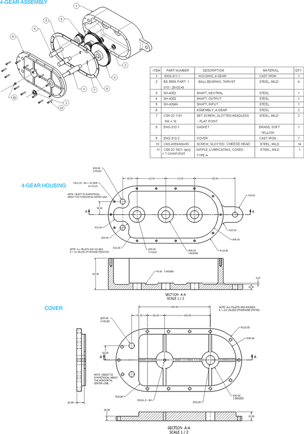
Draw an assembly drawing and parts list for the 4-gear assembly shown.

EX13-25
Perform the following functions for the slider assembly shown:
Select the appropriate fasteners.
Create an assembly drawing.
Create a parts list.
Specify the tolerance for the guide shaft/bearings interface.


EX13-26 Millimeters
Draw an assembly drawing and parts list for the cam assembly shown.
Cam parameters
Base circle = Ø146
Face width = 16
Motion: rise 10 by harmonic motion in 90°, dwell for 180°, fall 10 in 90°
Bore = Ø 16.0
Keyway = 2.3 × = × 16
Follower Ø = 16
Follower width = 4
Square key = 5 × 5 × 16
Bearing overall dimensions
DIN625-SKF 6203 (ID × OD × THK) 17 × 40 × 10
DIN625-SKF 634 4 × 13 × 4
GB 2273.2-87-7/70 8 × 18 × 5
Spring parameters
Wire Ø = 1.5
Inside Ø = 9.0
Length = 20
Coil direction = Right
Active coils = 10
Grind both ends

